Competency B1: Select Regulators, Valves, and Valve Train Components
Learning Task 4
Describe Automatic Gas Valves
Compared to manual gases that involve direct physical contact with a lever or hand wheel, automatic valves are controlled by electric, hydraulic, or pneumatic signals from sensors. The valves can be set to open, close, or modulate flow.
As was mentioned in the discussions on valve train components in LT2, the automatic valves control the flow of gas to the appliance burners. On a gas valve train automatic valves are used for one of two purposes either:
- A safety shut-off valve to protect against system failures
- Operating valve to control the normal on, off operation of the burners.
For appliances with inputs less than 400 MBH the appliance automatic safety shut-off valve and the operating valve are both included as part of a combination gas valve. The ways in which these two valves are actuated and sequenced is often tied to the type of flame detection system being used. It could be helpful to review the Plumber 3 Competency E-6, Select Flame Safeguards at this time.
Abbreviations and definitions used in this learning task will include:
- VAC – Volts Alternating Current
- VDC – Volts Direct Current
- mV DC – Millivolts Direct Current
- NTC – Negative Temperature Coefficient, used to describe a thermistor whose resistance decreases with increasing temperature.
- PTC – Positive Temperature Coefficient, used to describe a thermistor whose resistance increases with increasing temperature
- HIS – Hot Surface Ignition, AKA Glow Bar
- DSI – Direct Spark Ignition
- ECO – Energy Cut-Off
- TCO – Temperature Cut-Off
- FVIR – Flammable Vapour Ignition Resistant
- FV sensor – Flammable Vapor sensor
Automatic safety shut-off valve
The Automatic safety shut-off valve is one of the most important valves in the valve train and it may be an individual component or part of a combination gas control. Its function is to provide gas shut-down if a dangerous situation could result from the build up of gas with no controlled ignition source. The gas safety valve shuts off the gas supply when de-energized by a combustion safety control, safety limit control, or loss of actuating medium. Safety shut-off valves are most often electrically operated.
Automatic operating control valve
A sensing device will typically activate the automatic gas valve, allowing the gas to flow to the burners where ignition will take place. There are many types of automatic gas valves with various sensing devices and activation methods. Two common methods of operation include:
- Electric: a control circuit is energizes or de-energizes an electromagnetic solenoid to activate the valve. The control circuit is usually operated by 24 VAC but may be 120 VAC or mV DC.
- Mechanically (non–electric): mechanical sensing device such as a capillary tube with bellows, or rod and tube, acting directly as the valve operator.
Electric gas control valves
The majority of automatic gas control valves are electrically actuated and are primarily used to control gas flow to main or pilot burners.
Solenoid valve
The solenoid gas valve uses the elementary concept of electromagnetic coil which we will also see in many more complex gas valves. When the control circuit is activated it energizes the magnetic coil pulling an armature (valve stem) up into the coils center lifting the valve disk off of a valve seat. This allows gas to flow to the burner. When the controller is satisfied it opens the control circuit and de-energizes the electro-magnet (coil) causing the valve disk to fall back onto the seat from its own weight and the upstream gas pressure (Figure 41).
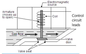
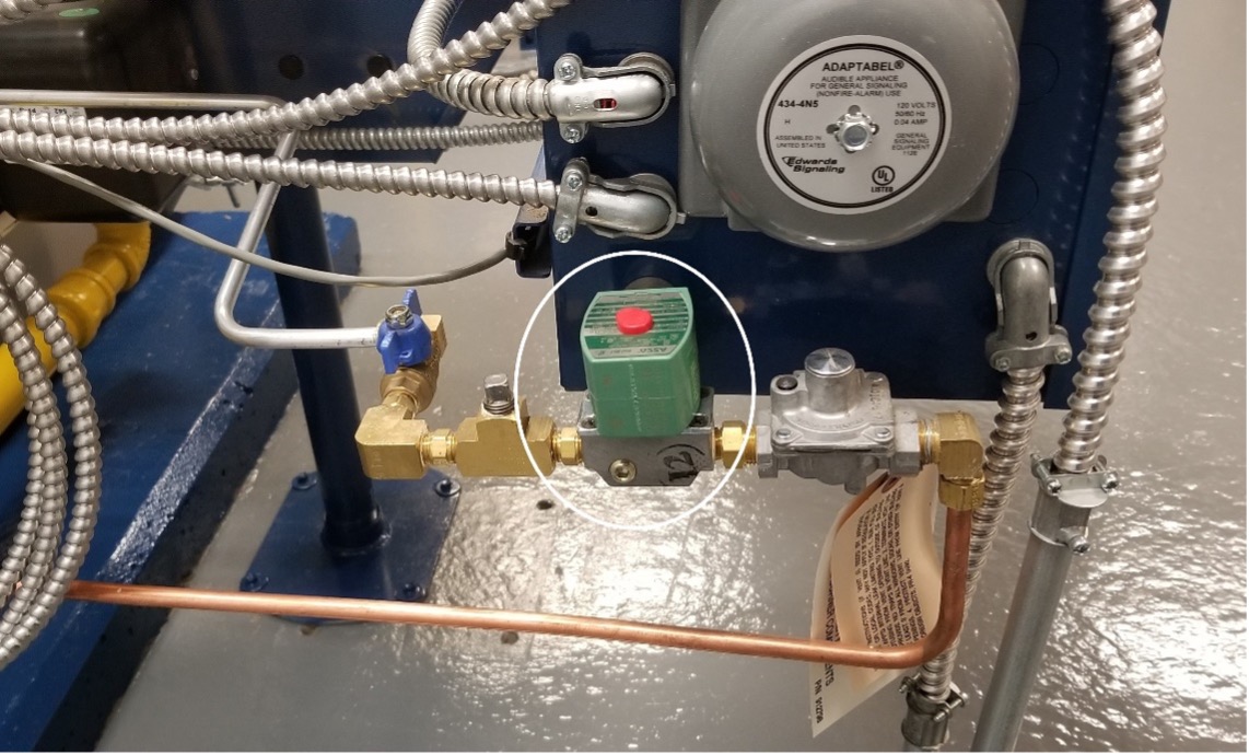
Some models may also have a very light spring to initiate the downward movement, but they all rely upon the weight of the disc and stem to seat them and must be installed in an upright position. This valve operates on 120 or 24 VAC circuits only (not millivoltage) and are commonly used on pilot lines of large input appliances (Figure 42).
Thermoelectric valve
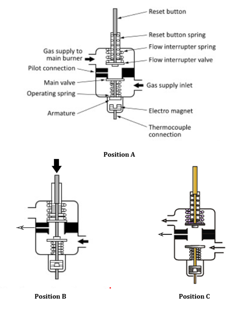
Thermoelectric gas valves are powered by DC current supplied by a thermocouple or thermopile. One example is the continuous pilot safety shut-off valve, powered from a thermocouple producing 30 millivolts. Thermoelectric safety shut-off valves are often referred to as Pilotstats, as they thermally monitor the status of the pilot flame. As long as the pilot flame exists the main burner will be safely lighted. If the pilot flame is not present then the flow of fuel must be shut off. If the flow of gas to both the main burner and the pilot burner stops, it is referred to as 100% safe. On some systems, only the main burner is isolated on pilot outage and gas flow is allowed to continue to the pilot burner. This type of system is referred to as non 100% safe, 80% safe or as a “wild pilot”. Figure 43 shows three different possible positions of the safety shut-off valve for a continuous pilot application:
- In position A, the thermocouple is deenergized and the valve is in the closed position, there is no gas flowing to either the pilot or main burners
- In position B, the reset button is being manually depressed. Gas can only flow to the pilot burner where it is manually lit. Once the pilot is lit, and the button is held, the thermocouple is heated by the pilot burner energizing the electromagnet.
- In position C, once the thermocouple is adequately heated it will produce enough voltage for the electromagnet to hold the main valve open when the button is released. In addition to the pilot, the gas is now also available to the operating automatic gas valve for the main burner.
- If the pilot were to be extinguished the thermocouple would cool, deenergizing the electromagnet, releasing the keeper, and returning the valve to position A.
Time of operation is an important factor with automatic safety shut-off valves. The maximum flame failure response time (F.F.R.T.), that is, the time elapsed from when the flame is lost until the gas valve is de-energized:
- 90 seconds for gases that are lighter than air when the appliance has a maximum input of 400 MBH.
- 20 seconds for gases that are heavier than air when the appliance has a maximum input of 400 MBH.
- 4 seconds for appliances with an input exceeding 400 MBH.
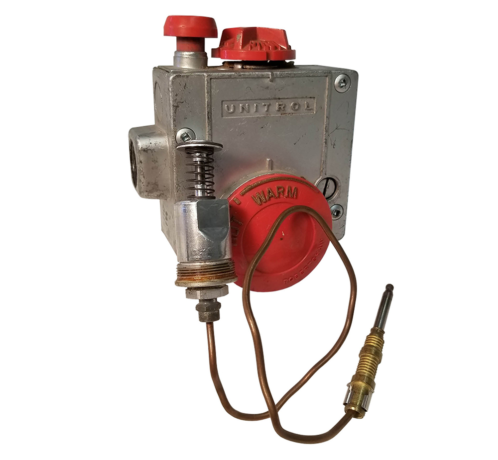
Figure 44 shows the pilotstat solenoid module (power unit) removed from a storage water heater combination gas valve, with a connected thermocouple. The module has been removed from the body of the valve aligned with its appropriate internal location. Notice that the pilotstat is the first internal component after the gas inlet, within the combined gas valve. Therefore the gas must flow through the safety shutoff valve before it is made available to the internal thermostatic automatic gas valve.
Diaphragm valve
The diaphragm gas valve (Figure 45) is a pilot operated solenoid-valve, in that it uses available inlet gas pressure as the primary force to open or close the valve.
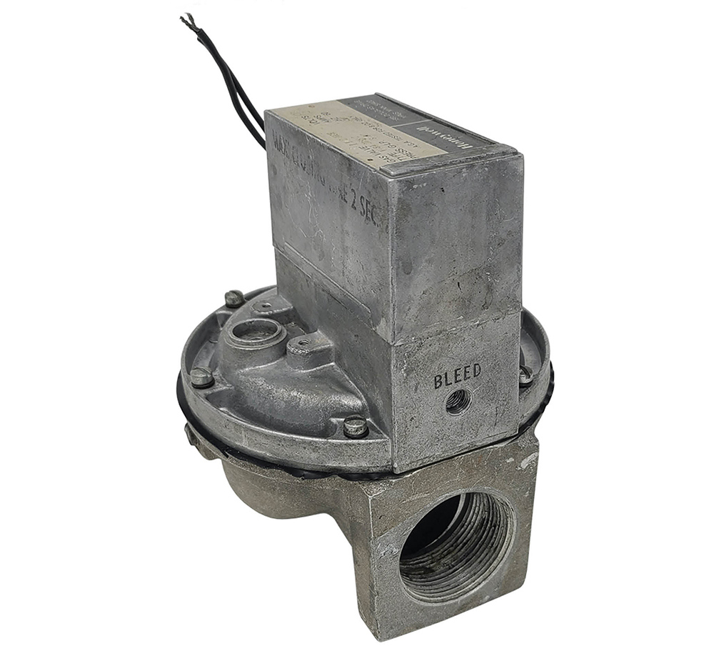
They are simply an on/off automatic valve, and do not regulate or modulate the flow (Figure 50):
- On a call for heat the electromagnet is energized.
- The electromagnet then pulls the armature into a position that blocks off the pressure port, allowing gas pressure above the diaphragm to bleed off through the vent port to a standing pilot flame (Figure 46 left).
- The pressure differential across the main diaphragm is greater than the spring force, so the diaphragm lifts the valve disc from the valve seat, allowing gas to flow through the valve to the burner.
- When the heat call has been satisfied, the electromagnet becomes de-energized and the armature return spring pulls the armature into a position that blocks off the vent port (Figure 46 right).
- Upstream working gas enters the pressure port and pressurizes the top of the diaphragm.
- When the pressures above and below the diaphragm are equal, the spring will cause the valve to move down to the closed position. Once closed the under-side area being acted upon by gas pressure has been reduced causing additional force on the top to increase the sealing force on the valve seat.
Note the diagram is not to scale as the pressure port is actually the size of a pin hole, therefore the armature and electro magnet can block gas flow with very little force. This enables diaphragm operated valves to be operated with lower voltage such as millivolts.

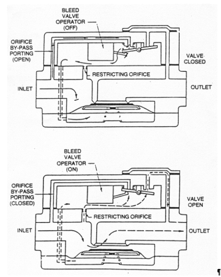
Although this style of diaphragm valve is rare today is serves well as an introduction to an important concept still used on most automatic gas valves. Figure 47 represents another more common version of the diaphragm gas valve. Notice some of the differences:
- An internal bleed line vents the gas back into the outlet chamber
- The valve disc is inverted and working gas pressure is diverted to the underside of the diaphragm
- The armature return spring is compressed when the operator is energized.
- The restricting orifice controls the valves opening rate.
Combination gas valves
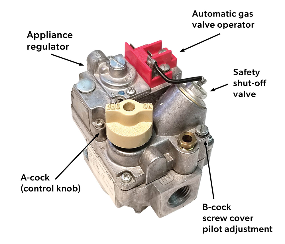
Combination gas valves will combine some or all of the valve train components into one unit. It is common for combination gas valves designed for less than 400 MBH/120 kW to include all of valve train components in the one valve body (Figure 48).
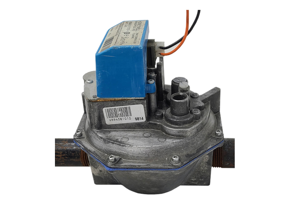
For larger inputs the combination gas valve may just combine a couple of components such as the automatic operating valve and regulator. The 1” regulating diaphragm gas valve shown in Figure 49 can be used for main burners rated for up to 1000 MBH. It is a slow opening valve that controls the on-off flow of gas to the main burner as well as regulating the manifold gas pressure to 3.5 “ wc.
Regulating diaphragm gas valve operation
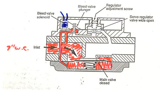
The regulating diaphragm gas valve is also known as a Servo gas valve as it has a small servo pilot regulator to position the diaphragm seat. The Servo gas valve uses the same principle as the diaphragm gas valve, in that it manipulates a small amount of upstream gas pressure into the working chamber of a diaphragm. Whereas the diaphragm valve was strictly an open or closed valve the servo gas valve can also act as a pressure regulator by partially opening or closing the main valve seat.
The stages of operation:
When the controller is not calling for heat (Figure 50), the bleed valve solenoid coil is not energized. The plunger in the actuator is in the down position, blocking the bleed vent. Inlet gas pressure passes through the restrictor and down the bleed line to build pressure under the main valve diaphragm. The gas pressure is equal above and below the diaphragm. The force of the spring and the fact that the area of the lower diaphragm surface is greater keep the valve closed.
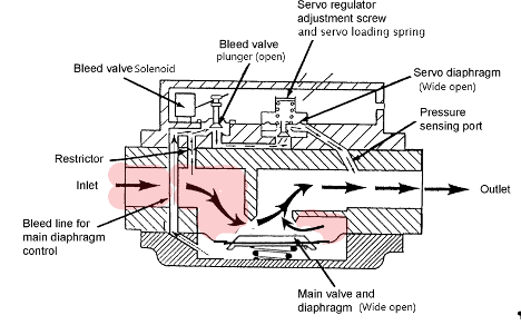
On a call for heat, the bleed-solenoid is energized and lifts the bleed valve plunger (Figure 51). Gas under the main diaphragm evacuates through the bleed line and valve and on through the open servo regulator to the outlet of the main valve. The gas pressure on the top of the main diaphragm now overcomes the effects of the spring and the reduced gas pressure under the diaphragm and the main valve opens. (Note that the gas can be bled out faster through the servo regulator opening than it can enter through the small restrictor orifice or the lower chamber would not bleed.)
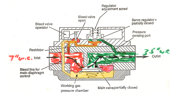
As the pressure increases at the outlet of the main valve, it is transmitted through the pressure-sensing port to the lower side of the servo regulator diaphragm (Figure 52). This rise in pressure causes the servo regulator to compress the servo loading spring. The servo disk moves upward and the flow of bleed gas to the main valve outlet is now restricted. This increases the pressure in the working gas pressure chamber and raises the main valve towards its seat, decreasing the flow rate. The servo regulator continues to sense the main valve outlet pressure and then controls the bleed rate to create a working gas pressure that will hold the main valve disk in a position that will match the required flow rate at the required setpoint pressure.
After the controller is satisfied, or if there was a power outage, the solenoid coil is de-energized and the valve returns to the closed position shown in figure 50.
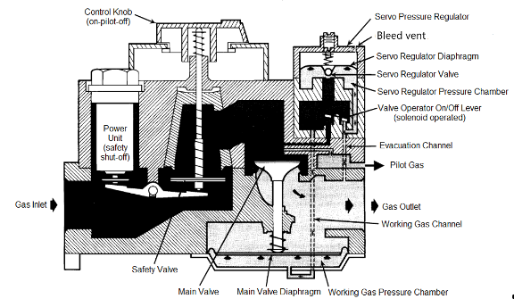
The previous diagrams have been created for explanation purposes. The arrangement of the internal components and the direction of movement will vary when you are looking a manufactures cutaway diagrams (Figure 53) but the concept of using a small servo operated pilot regulator to position the main valve seat is consistent. Notice that the safety shutoff valve has now been included as the first internal valve. This cutaway represents the inner working of a valve similar to the previous picture shown in Figure 49. Just like any other regulator, the small servo regulator has a bleed vent above the diaphragm to allow the free movement of air to and from the upper diaphragm chamber. Because these valves are installed indoors the vent has a built-in restricting orifice to limit the amount of gas that would escape in the event of a rupture of the servo regulator diaphragm.
Redundant gas valves
Since 1979 all heating combination gas valves have been required to be dual seated valves, or on millivolt systems have an extra limit that disconnects the valves power supply. To accomplish this combination gas valves will have a second automatic shut-off valve incorporated into the valve body. This second (redundant) valve gives an extra level of protection against gas entering the combustion chamber if the main valve seat were to leak while in the closed position.
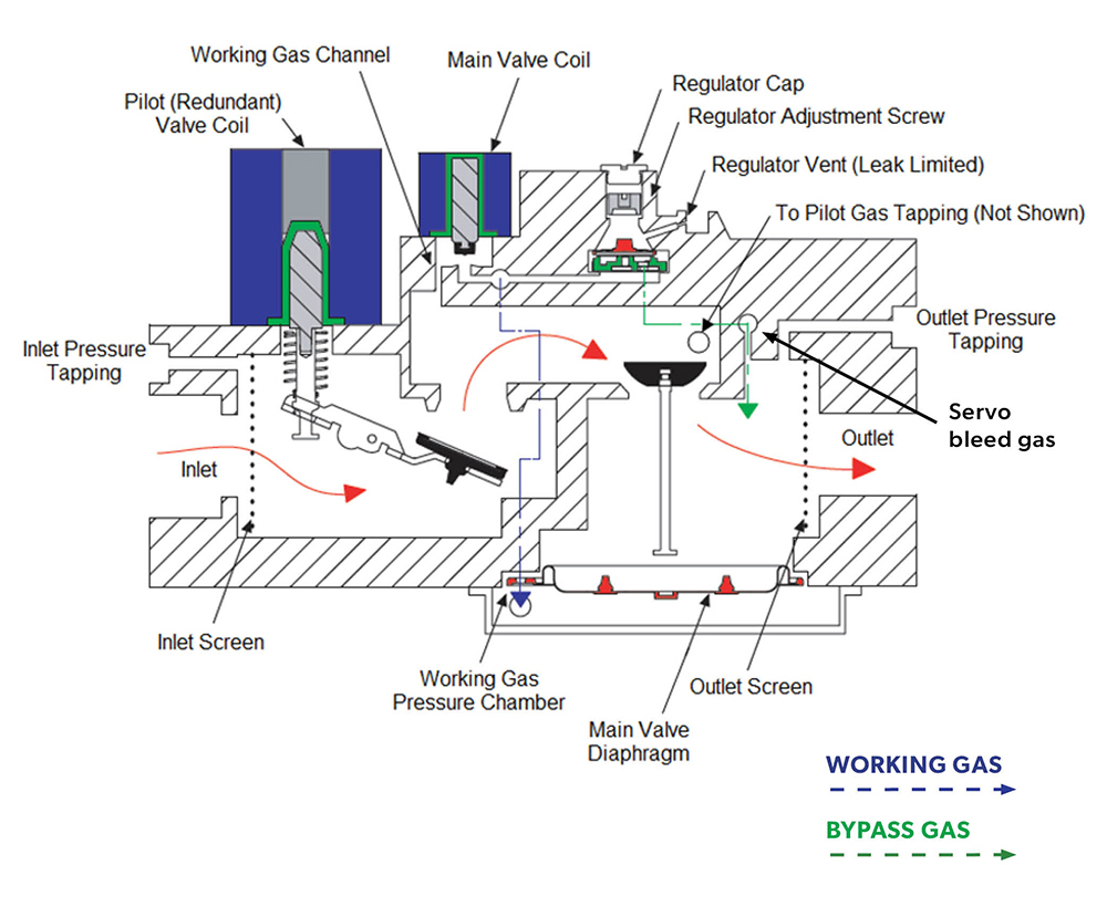
The redundant gas valve is also a diaphragm style servo regulated valve similar to the previous Figure 53. When you compare to Figure 54 you can see that the redundant valve coil uses a 24 VAC solenoid actuator rather than the 30 millivolt safety shut-off valve shown in Figure 53.
When set up to operate with an intermittent pilot, the following sequence of events occur:
- With no voltage applied to the valve both the main and pilot valves are in the closed position and the gas is being held at the inlet port by the pilot valve.
- The controller calls for heat and after a pre-purge period the pilot coil is energized and opens the pilot valve. The pilot gas uses the valve inlet pressure and it is not regulated, instead it can be throttled with an internal needle valve that is not shown.
- Gas is delivered to the pilot burner where it is ignited by spark igniter. Once the pilot flame is proved, by a flame detection circuit, the spark igniter is de-energized.
- The pilot flame is confirmed and monitored, then the main valve coil is energized allowing gas to flow through an internal channel into the working gas pressure chamber on the underside of the diaphragm forcing the main valve open and gas flows to the main burner where it is ignited by the pilot burner.
- The servo regulator senses the main valve outlet pressure and then controls the servo bleed rate to create a working gas pressure that will hold the main valve disk in a postion that will match the requred flow rate and setpoint pressure.
- When the call for heat is satisfied the controller opens its contacts and both the pilot valve and the main valve solenoids are de-energized and the flow all gas stops.
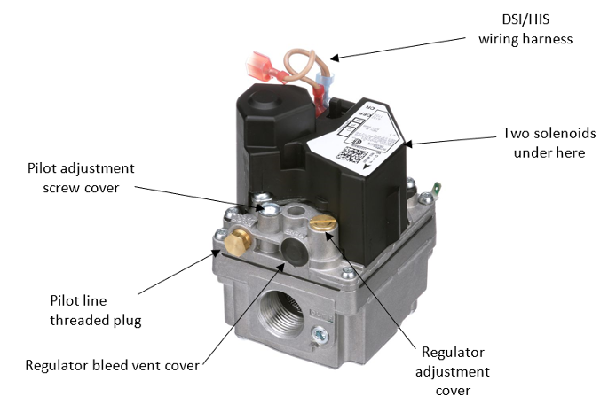
The valve may also be set up to operate with an electronic ignition system that lights the main burner directly without the use of a pilot flame. When used on a main burner HSI or DSI systems a wiring harness is used to energize both the pilot and main valve operators simultaneously. There will also be a threaded plug installed in the pilot line connection (Figure 55).
Regulator bleed vent cover shown in the picture serves as a dust cover only as the leak limiting orifice is internally built into the vent opening.
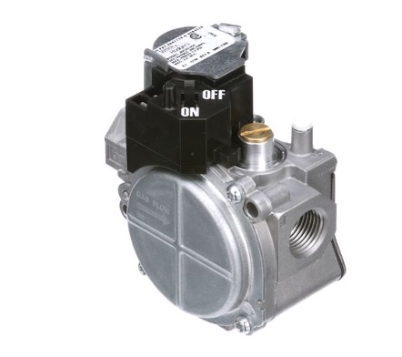
For some styles of redundant gas valves, used only on Direct ignition systems (DSI/HSI), the two operators are internally wired together and there is no pilot tapping (Figure 56). This valve has also been designed to be very compact. Notice the regulating valve’s large diagram chamber visible on the side of this valve.
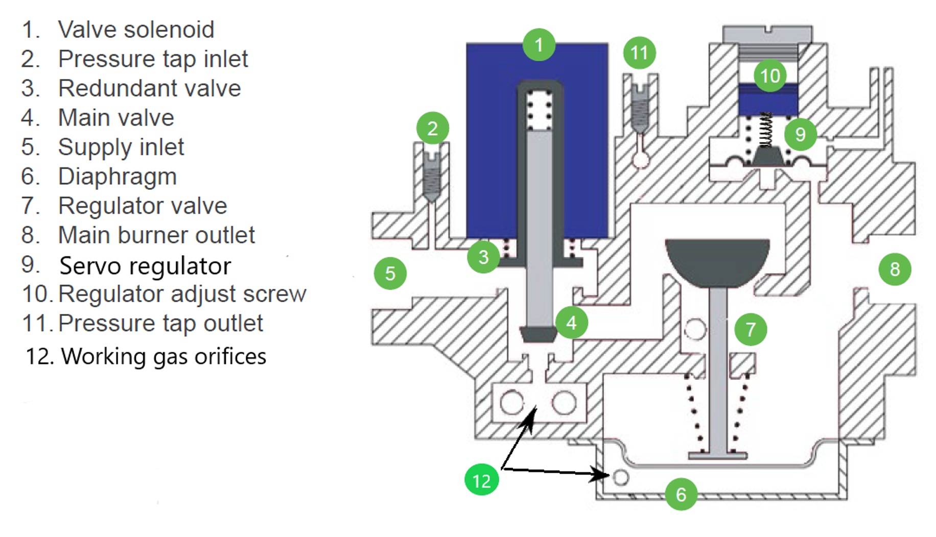
Additionally, because there is no pilot gas requirement, both the main and redundant valve seats are combined into one double seated solenoid valve (Figure 57). The regulating valve is held closed until the main valve seat sends gas pressure to the underside of the diaphragm via the working gas orifice and passages (not all shown). The working gas pressure is then controlled by the servo regulator to position the regulating valve.
Referenced servo regulator pressure
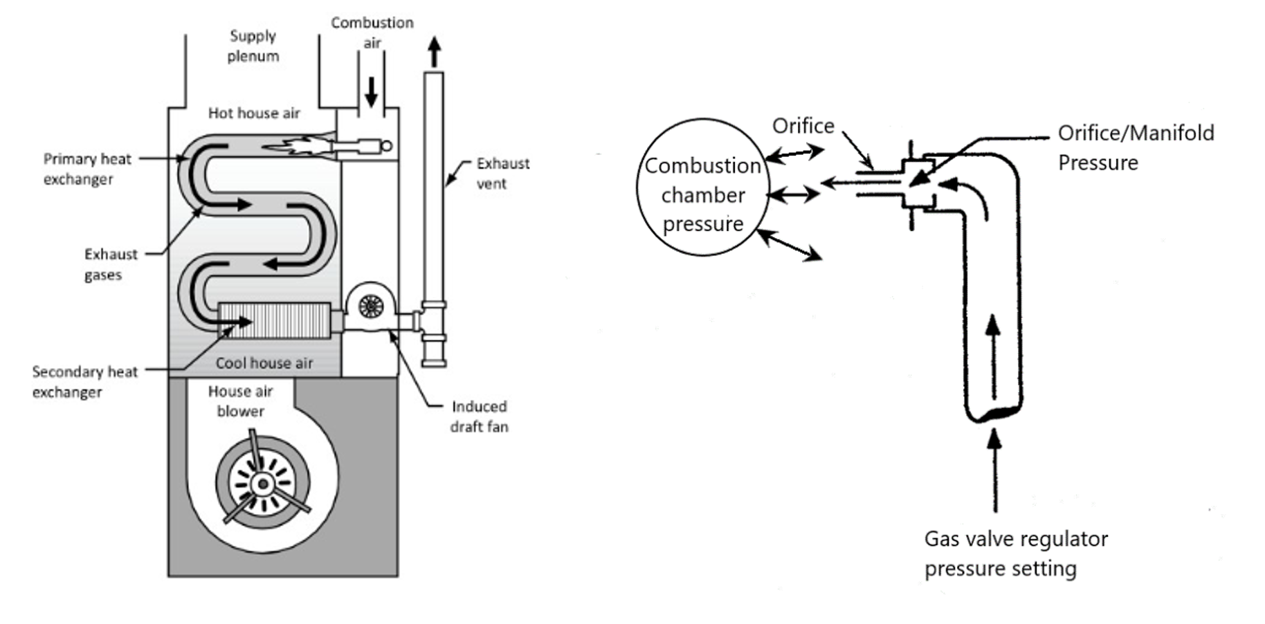
Many modern appliances are fine tuned to adjust to changing conditions while still delivering accurate gas pressure to the combustion chamber. To look at such a valve, it is important to understand the pressure drop across a burner orifice is determined by the manifold pressure of the appliance. It is normally the difference between the manifold pressure and the atmospheric pressure surrounding the orifice outlet.
For most high efficiency gas furnaces the combustion air is drawn into the appliance by an induced draft fan and the combustion chamber will experience a non-atmospheric pressure condition, in this case negative or vacuum (Figure 58). This would change the pressure differential across the gas orifice and alter the gas flow to the burners. The manifold pressure must equal the required orifice ∆P plus the combustion chamber pressure. For example, if the orifice was sized for a pressure differential ∆P of 4” wc and the combustion chamber had a negative pressure (vacuum)of 1” wc, then the servo regulator would need to be adjusted down to 3” wc to maintain the correct gas input (∆P 4” + (−1”) = 3”).
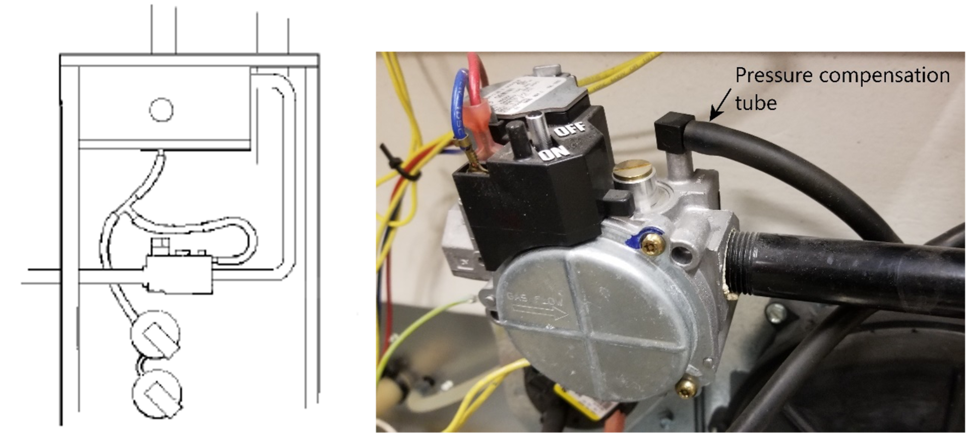
Every installation will have different vent configurations which could result in different effects on the amount of combustion chamber vacuum. Additionally, their will be fluctuations for changing barometric conditions. By connecting a combustion chamber pressure compensation tube to the regulator bleed vent opening of the gas valves servo regulator, the combustion chamber negative pressure is applied to the loading element side of the regulator diaphragm (Figure 59). This will enable the regulator to automatically change the manifold pressure and maintain a constant pressure differential across the orifice. The compensated manifold pressure is often referred to as referenced manifold pressure. Notice that there are also two pressure switches connected to the reference tube as part of the ignition safety controls to verify the fan is operating properly.
Staged and modulating combination gas valves
For high efficiency condensing appliances it is important to try and match the firing rate to the systems heat demand. Reducing the gas input during low load conditions will ensure the appliance achieves maximum efficiency. There are a number of different approaches used to changing the appliance input that depend on the type of appliance and how much variation is needed. The two most common variable input schemes include:
- Multistage input
- Full modulating input
Multistage input
Multistage heat production divides the total heating output into a number of increments, or stages. As the load increases, the stages are turned on sequentially. Multistage input has been used for many years on commercial heating plants by splitting the total building load into multiple modulating boilers.
Residential forced air furnaces are often two stage (dual stage). The lower input allows the unit to conserve energy and reduced temperature fluctuations by operating more continuously. Most of the time, the furnace will run at low fire. If outdoor temperature drops drastically, the furnace can use its high fire mode to maintain the desired building temperature.
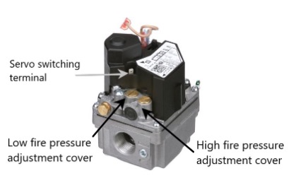
A two-stage gas valve is used with a two-stage thermostat to supply fuel in quantities necessary to meet the staged demand (Figure 60). The valve has two servo regulators, to enable it to supply lower manifold pressure and less fuel on a first-stage heating call. When the second stage is energized, the high-fire pressure servo-regulator is activated and 100% fuel flow is sent to the burner. Notice this valve body is very similar to one of the previous images with an extra servo regulator adjustment cover and an additional wiring connection to activate the servo switching solenoid valve. Typical pressure ranges are: low-fire 1-1.5 in. WC; high-fire 3-4 in. WC.
Modulating input
A gas burners turndown ratio is the ratio of maximum heat output to the minimum level of heat output at which the appliance will operate efficiently or controllably. A fully modulating burner controller will alter the firing rate to match the load over the whole turndown ratio. For example, a 100000 Btuh modulating condensing boiler with a 10:1 turndown ratio could supply a load range from 100000 to 10000 Btuh and any point in between.
During this process, the gas burner must stay at the correct fuel-to- air ratio across the complete firing range to ensure the maximum combustion and boiler efficiency. This task is performed by an electronic controller which analyses number of different operating parameters to determine the correct firing rate.
Gas appliance manufacturers typically take one of two approaches to pressure modulation by a combination gas valve:
- Zero governor/ratio regulation.
- Modulating electric actuators
Zero governor/ratio modulation
The concept of venturi mixers and zero governor regulation was previously introduced in Learning Task 3. In this case the modulating mechanical mixing burner uses a variable speed blower to adjust the combustion air flow. In order to maintain proportional mixing the zero governor servo regulator, within a combination gas valve, automatically changes the gas flow to match the air flow. These flow adjustments are dependent upon the amount of vacuum generated by the air velocity flowing through the venturi (Figure 61). Remember the zero governor servo regulator is trying to maintain atmospheric pressure at P2. Just like all other servo regulators it will use the supply pressure to create the necessary working pressure onto the working diaphragm that will position the operating valve as needed.
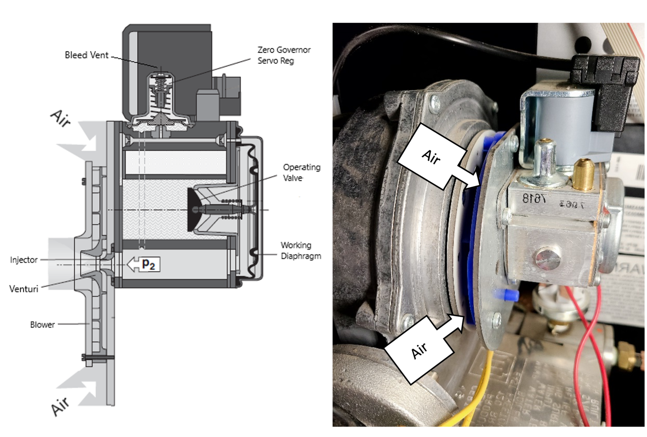
As was previously explained zero governor regulators control the outlet pressure with a goal of zero pressure, relative to atmosphere. They allow the flow of gas to only occur when a negative pressure is sensed at the injector, which is conveyed to the underside of the servo regulator diaphragm. The upper side of the servo regulator diaphragm bleed vent is sensing ambient air pressure. For direct vent appliances the air supply shown in Figure 64 is supplied through a pipe. This pipe creates some resistance to the blower suction; therefore, the air being supplied to the venturi will already be at a slight negative pressure. It is important that the regulator does not interpret this additional negative pressure at the injector as being generated by the venturi and add to much gas. As long as the bleed vent is also sensing the negative supply air pressure onto the upper side of the diaphragm it will cancel out the air supply negative, and only sense the vacuum created by the venturi velocity.
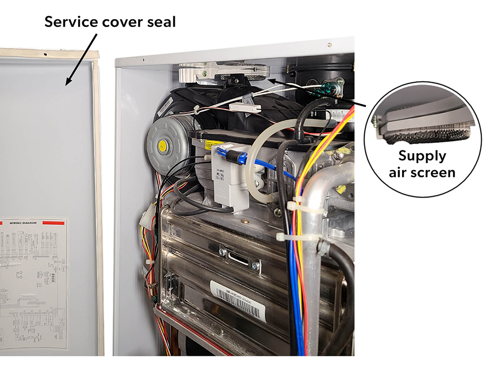
For many small, wall-hung boilers and on-demand water heaters (Figure 62) the air supply pipe is only connected to the appliance cabinet. The service cover has a seal to separate the combustion air supply from the room, essentially making the cabinet an air supply duct for the blower inlet. Therefore, the bleed vent of the zero governor servo regulator, also located within the housing, is sensing the same pressure as the blower inlet.
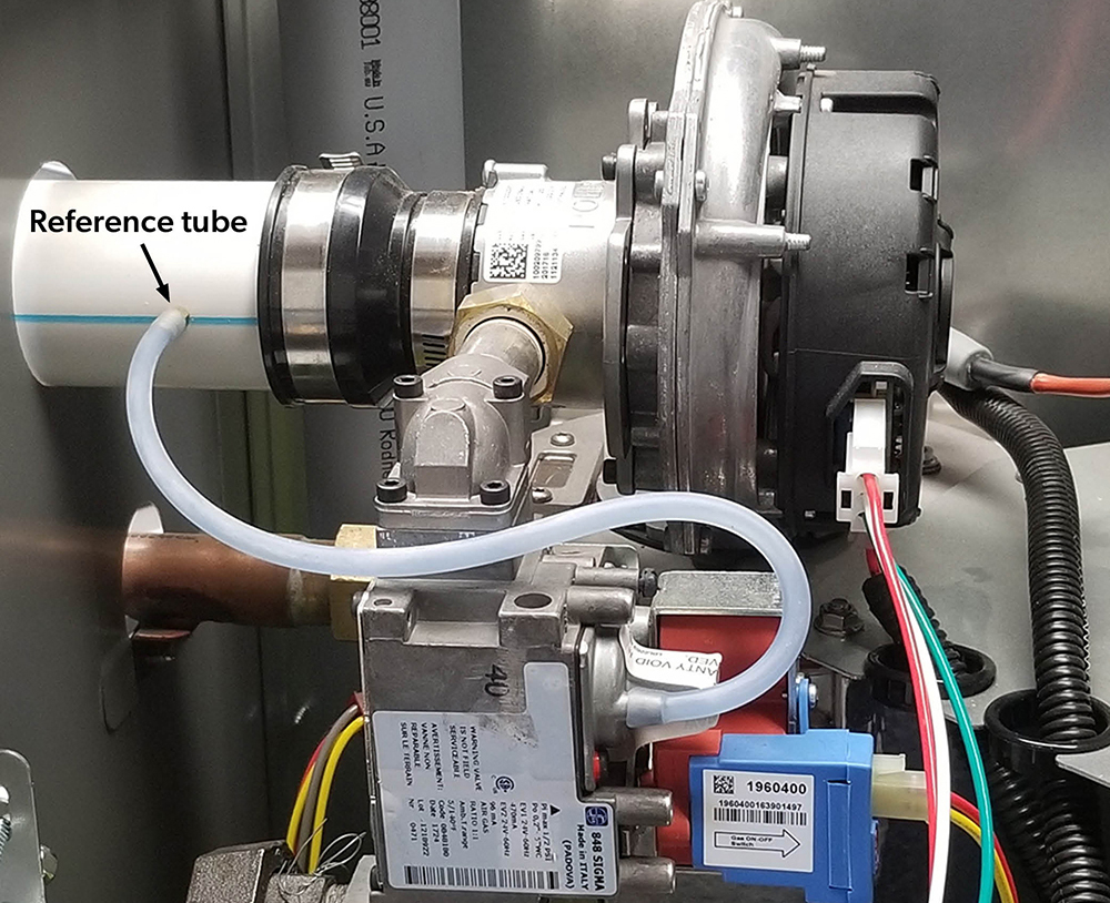
On some modulating venturi mixing burners the air supply pipe is connected directly to the blower inlet (Figure 63). In these cases, a pressure compensation tube will be connected upstream of the venturi to the bleed vent of the zero governor servo regulator. This will neutralize the negative pressure created by the resistance of the air supply piping.
Modulating electric actuators
Another approach to gas valve, pressure modulation is to replace the servo regulators adjustment screw and spring with an electric actuator. Modulating electric actuators have an internal system that positions the output shaft proportional to an input control signal. Unlike on-off electric actuators, modulating actuators do not necessarily travel the full span from open to close in one movement, but move only according to the change in the input control signal. Typically, the analogue control input signal is 0-10VDC, or 4-20mA. The proportional positioning is set by the input signal, say 0-10V where 0V is closed and 10V is open, 5V is 50% open. Therefore, the actuator can vary the manifold pressure setting from low to high-fire pressure, or any point in between based upon the signal from the controller. The controller will constantly monitor the outlet pressure and other system feedback sensors to adjust the servo regulator setting. There are two types of electric positioning actuators used on combination gas valves, to adjust the servo regulator loading force.
- Modulating solenoid actuators
- Stepper motor actuators
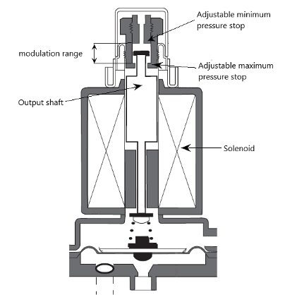
The servo regulator portion of a combination diaphragm gas valve shown in Figure 64 has a modulating solenoid actuator. Notice there is are adjustable maximum and minimum pressure stops. The image shows the solenoid is holding the output shaft approximately midway of its full travel range. This position adjusts the spring force to about 50% of its pressure setpoint range. Some appliances will adjust the maximum pressure setting with a potentiometer on the controller to limit the control signal output at high fire.
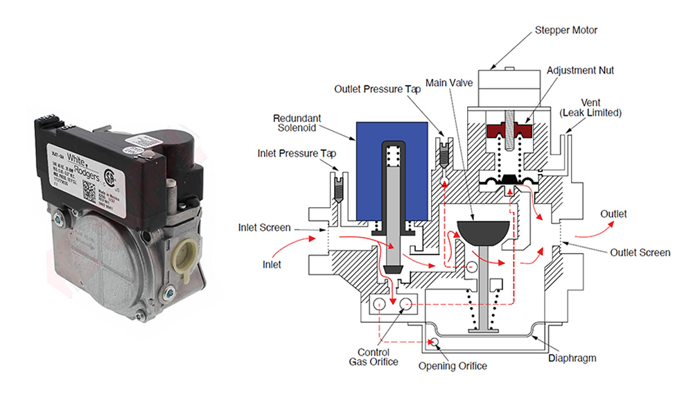
The use of a stepper motor is another common method of modulating the servo regulator setting. A rotating DC motor operator is used to turn the pressure adjustment screw to the desired setting. For example, the valve shown in Figure 65 has the same body and internals as a redundant gas valves previously introduced in Figure 56 and 57 with the addition of the DC stepper motor operator. These valves can achieve a full range of modulation from 35–100% with 1% increments. Notice the stepper motor rotates a threaded spindle which moves the adjustment nut up or down to change the gas pressure setting.
Self energized automatic gas valves
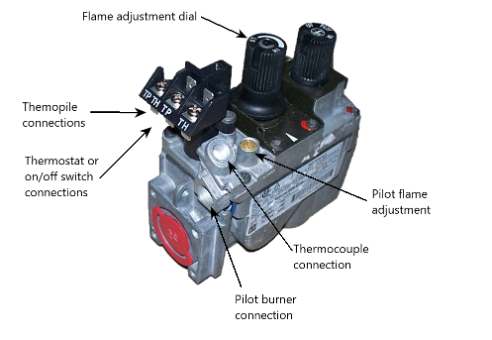
Self energized gas control valves have solenoids that operate with 750 mV supplied from a thermopile heated by the pilot flame. Notice the power supply wiring connections on the combination valve in Figure 66 are labeled TP for Thermopile. Other manufactures will also use the abbreviations PP (powerpile) or PG (pilot generator). This valve has a separate thermocouple connection which is necessary configuration for direct vent appliances that require a fast-acting flame failure response. There is also a manual main burner adjustment dial which is essentially an extension of the servo regulator adjustment screw. The pilot flame pressure is not regulated and has a separate adjustable needle valve.
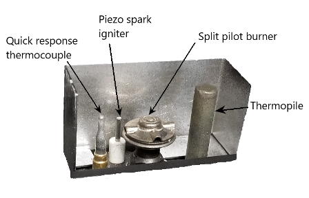
The pilot burner for this valve uses a split pilot flame with a quick response thermocouple to energize the safety shut-off and a thermopile to power the main valve (Figure 67). On unvented gas heaters this same quick response thermocouple set up is used with a special ODS pilot burner (Oxygen Depletion Sensor). If the oxygen content in the room drops the pilot flame actually lifts off the thermocouple cooling it down and causing the gas valve to close and the heater to shut off.
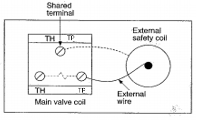
Another configuration of a millivolt gas valve uses the thermopile to energizes both the pilot safety and the main valve circuits. You can see in Figure 68 that both the pilot valve and the main valve are wired in parallel to the Thermopile (TP). The thermostat (TH) will only turn on/off the main valve.
Because it takes longer for a thermopile to cool off and shut off the pilot valve these are only used on gravity vented appliances that do not require rapid shut-off in the event of flame failure.
Battery operated gas valve
To meet efficiency standards continuous pilot fireplaces are being phased out in favour of DC low voltage electronic ignition systems, which use common dry cell batteries as the power source. The receiver/control module will have a compartment in which to install four AA batteries or a separate battery holder that plugs into the module (Figure 69).
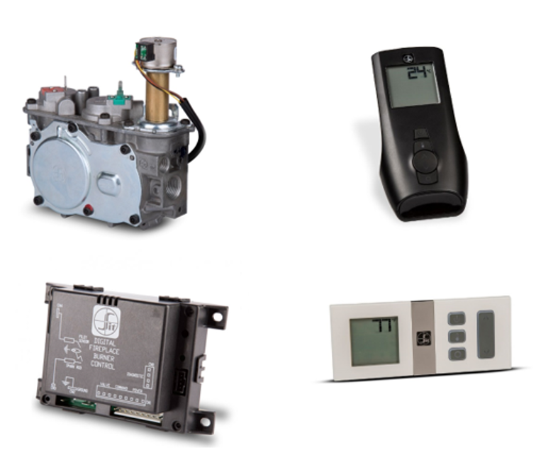
All components of the control circuit will be from the same manufacturer, designed to work with each other on 6 VDC. These systems can include options to modulate flame height and heat output as part of the temperature control system.
Storage type water heater gas valves
Similar to previously introduced combination gas valves, the control valves for a storage water heaters have multiple components within a single control. Depending on the style of gas valve, some of the safety and operational functions may include:
- Manual shutoff
- Pressure regulator
- Pilot adjustment screw
- Safety shut off control
- Water temperature control
- High limit energy cut-off (ECO)
- Combustion chamber thermal cut-off (TCO)
- Flammable vapour ignition resistance (FVIR)
For most types of storage water heater gas valves, the body of the valve contains a water temperature sensor (aquastat) contained in an immersion well. The entire valve then gets threaded into an opening in the side of the tank to mount the valve and immerse the sensor into the water.
Storage water heater control valves can be put into two categories, as either standing pilot or intermittent pilot. Another common grouping is non-electric (rod and tube) or electric.
Standing pilot types
Standing pilot, storage water heater gas valves are of two types: non-electric (rod and tube) or self energized (millivolt). One of the advantages of conventional standing pilot storage water heaters is that they can produce hot water during a power outage.
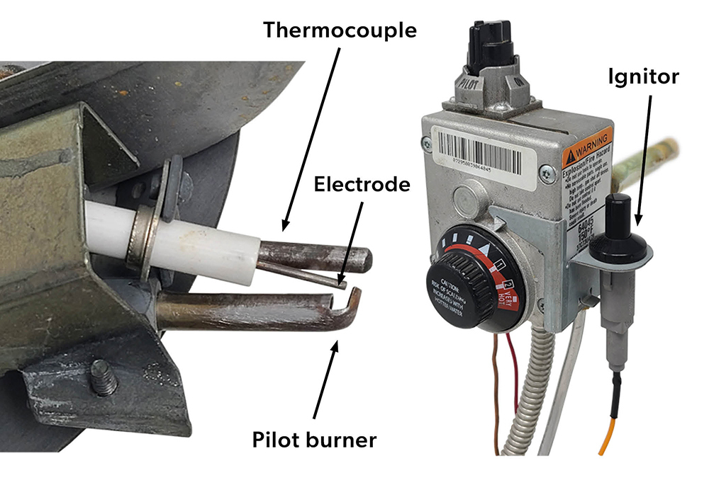
Standing pilot types (Unitrol) will require a pilot burner assembly complete with a thermocouple or thermopile and a pilot piezo igniter (Figure 70). If the pilot flame is extinguished for any reason the internal pilot safety shutoff valve will be deenergized and shut off.
Non-electric rod and tube gas valves
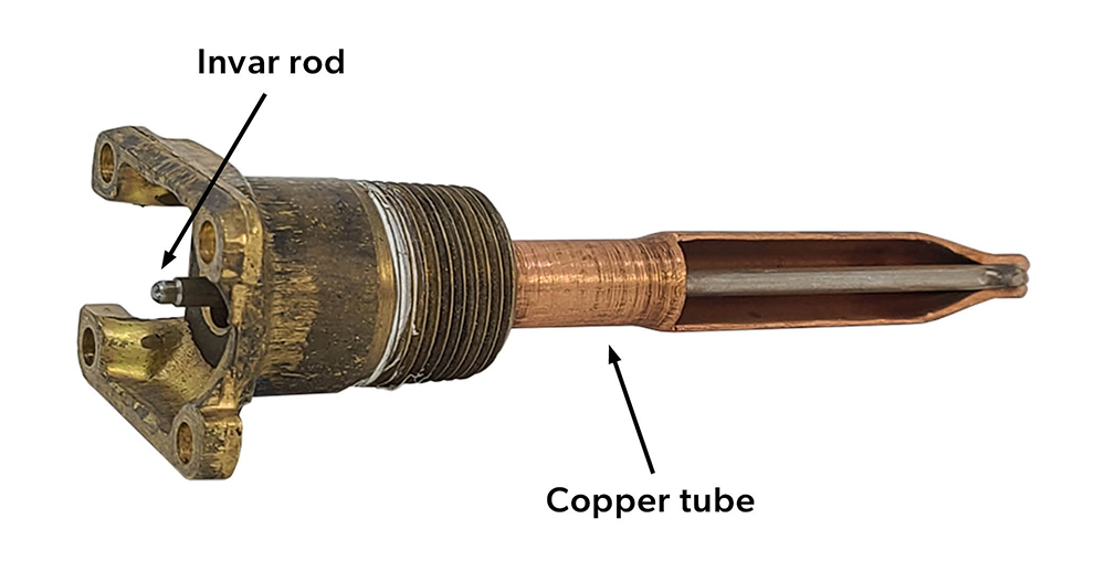
On the rod and tube gas valve the main burner is activated by a thermal mechanical sensor made up of a copper tube and invar rod assembly. In Figure 71 the edge of the copper tube has been ground away to expose the internal rod. The copper tube has high expansion and contraction rate, whereas the encased rod is made of a metal alloy called invar which has a very low expansion and contraction rate. The rod and tube are only connected together at the immersed end so temperature changes of the water cause the copper tube to expand and contract, forcing the control end of the Invar rod to move in and out of the valve body.
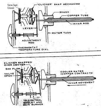
The upper diagram of Figure 72 shows the valve in the closed position so the main burner is off. As the water in the storage tank cools the copper tube will contract and end of the invar rod pushes on the lever slowly moving the clicker snap mechanism. The lower diagram of Figure 72 shows that once the internal disc has moved past its center the clicker opens the gas valve and gas flows to the main burner. Typically, the stored water drops about 8°C (15°F) to 11°C (20°F) from the temperature setpoint before the burner is activated.
Upon heating, the copper tube expands and moves the invar rod to the right away from the valve. This allows the clicker mechanism to return to its normal position and the valve spring to close the valve. The temperature dial position determines the maximum thermostatically controlled water temperature sensed by the copper tube. Rotating the temperature dial moves the adjustment rod in or out, changing the lever position and the temperature at which the invar rod activates the clicker mechanism.
Water high limit energy cut-off (ECO)
An energy cut-off (ECO) device is a safety limit used on rod and tube gas control valves. The ECO is a temperature-sensitive fusible link wired in series between the thermocouple and the pilotstat, so the 30mV produced by the thermocouple passes through it on its way to the pilotstat coil. In Figure 73 the copper tube has been cut to expose the fuse located alongside the invar rod.
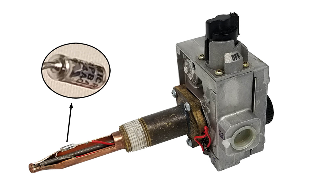
If there is a gas valve failure that causes the water temperature to exceed 93°C (200°F), the ECO will melt, breaking the safety circuit, and shutting off gas flow to the burners. The ECO is a single use safety switch and requires the replacement of the entire gas valve to put the water heater back into service.
Combustion chamber thermal cut-off (TCO)
The storage water heater safety system also includes a manual resettable, safety switch which is designed to disable the gas control/thermostat in the event of excessive combustion chamber temperatures. The thermal cut-off (TCO) is mounted into the inner sealed combustion chamber cover door and wired in series into the safety circuit with the ECO (Figure 74).
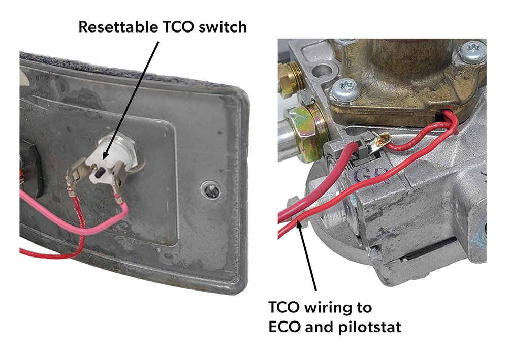
The excessive combustion chamber temperatures may be generated by a restriction to the combustion air flow, such as an accumulation of lint and dust on the flame-arrester (located underneath the combustion chamber). The TCO is also part of the manufacture’s flammable vapour ignition resistant (FVIR) system in that the TCO will trip if there is ignition of any flammable vapours, such as gasoline, inside the combustion chamber.
Self-Energized
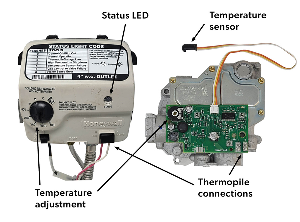
A self-energized style of standing pilot water heater gas valve uses a thermopile instead of a thermocouple. The use of a 750 mV thermopile enables the pilot flame to generate enough electrical energy to power a circuit board inside the gas valve (Figure 75). The combustion chamber TCO is still wired in series with the two wires from the thermopile, (red and white), which are plugged into the front of the gas control valve where they connect to the circuit board (micro controller).
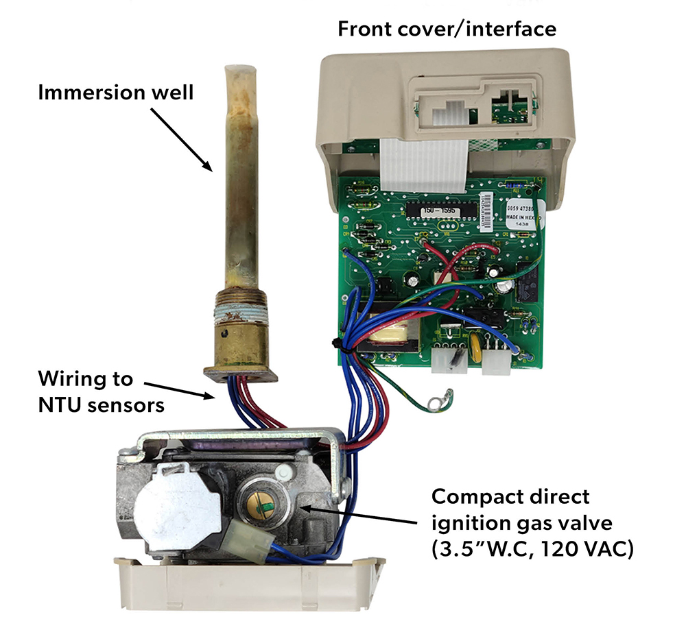
The micro-controller compiles the status of heater operation, issues error codes via an LED status light, and controls the operation of main burner. Instead of a rod and tube the water temperature is sensed by two matching negative temperature coefficient (NTC) thermistor sensors located in the immersion well. Thermistors are heat sensitive variable resistors, so a change in water temperature changes the resistance of the thermistors. The gas control circuit board interprets the thermistor resistance to accurately conclude the water temperature and turn the burner on or off. Having two thermistors provides a safety backup; if the micro controller reads a different temperature between the thermistors the system goes into error mode. The COM terminals are a communication connection that enable the water heater manufacturer to connect additional accessories, such as a timer or Wi-Fi controller.
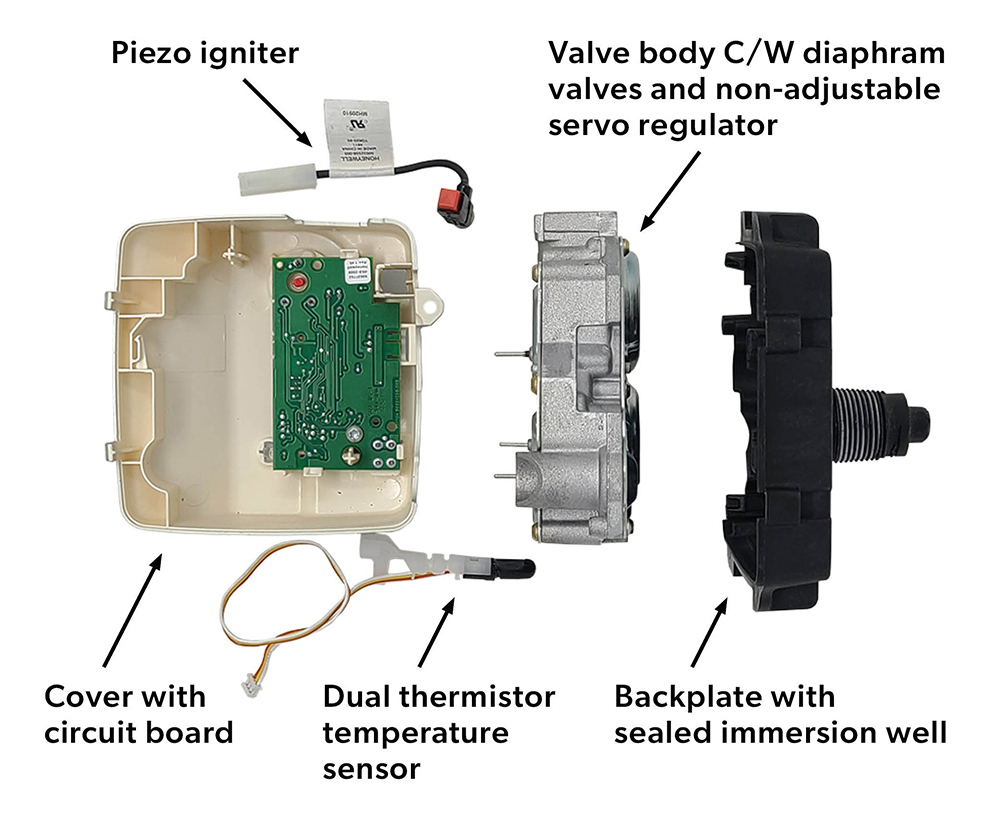
The gas valve is made up of five major components (Figure 76); designed so that any one of them may be replaced without replacing the entire control valve, or draining the tank, as the plastic backplate and immersion well can remain installed.
Intermittent pilot types (electric)
Storage water heaters with higher efficiency ratings will have electronic ignition instead of a continuous pilot. They may also have power vent blowers, dampers, and condensing heat exchangers. These water heaters require a 120 VAC power supply to run the blower, and cannot produce hot water during a power outage.
Some models and brands of gas valve have an internal transformer that converts the 120 VAC into 24 VAC to power the gas valve, while other heaters use 120 VAC supply to operate the gas valve (Figure 77).
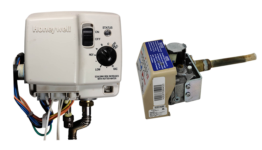
These valves will also use dual NTC thermistors in the immersion well to measure the water temperature (Figure 78). In addition to the task of operating the gas vale to maintaining the water temperature, the internal micro controller will also activate, monitor and self diagnose the; vent blower, pre-purge period, vent pressure switch, electric igniter, electronic flame sensor, vent temperature switch, water temperature high limit (ECO), and flammable vapour (FV) sensor.
Flammable Vapour Ignition Resistance
For power vented water heaters the electric gas valves used a Flammable vapor (FV) sensor as part of the FVIR system, to sense flammable vapors before they enter the combustion chamber. This is different than the standing pilot water heater, which used the TCO to react to the ignition of flammable vapours in the combustion chamber.
The FV sensor is located on the on outside lower front of the water heater within a protective plastic cover. In Figure 79 the plastic cover has been removed and the sensor separated from the base mount. Notice there are many air openings in the sensor protective housing, if the free flow of air to the sensor is blocked or has been covered with dust, leaves, water etc., it will not function.
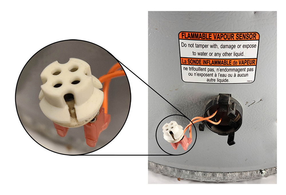
If the FV sensor detects the presence of flammable vapours while the water heater is operating, the gas control will switch to lock-out mode and the water heater will shut down. If the water heater is not operating when the flammable vapours are detected, the control will switch to lock-out mode and prevent the water heater from lighting.
After a flammable vapour incident has occurred and the flammable vapours have dissipated, the FV sensor is designed to automatically reset itself. However, the gas valve controllers may go into lock-out mode and will need to be manually reset. In most instances, there will not have been ignition of flammable vapours inside the combustion chamber because the FV sensor will have detected these vapours and shut down the water heater.
The sensor must have continuity, so a small current of electricity can pass through the sensor that signals to gas control valve that no gasoline vapor is detected. The FV sensor is easily tested using multimeter and can be replaced by plugging new one into the terminals
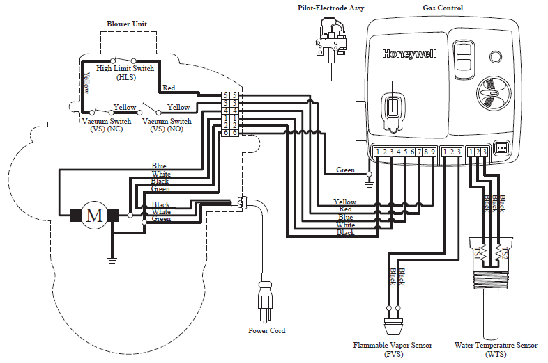
On standing pilot water heaters, the TCO also protected the unit from restricted combustion air flow. Whereas on these electric units instead of the TCO a high vent temperature switch (HLS) is used, as shown in Figure 80 as a component on the blower unit.
Non electric gas valves
Besides the Rod and tube gas valve there are a number of other non -electric gas valves. Some are used for temperature control others are used as specialty safety valves.
Hydraulically operated
Hydraulically operated gas valves are a type of non-electric gas control valve used for temperature control on cooking, fireplaces, and free standing space heating equipment. These appliances will have a pilot burner and the hydraulic actuator will only control the flow to the main burner. Hydraulic actuators are also referred to as hydraulic thermostats or a capillary tube device as the operator is made up of a sensing bulb filled with a liquid that has a high coefficient of expansion.
When a temperature change is sensed by the bulb it causes a change in the volume of the liquid. The liquid volume change is transferred through a capillary tube to a sealed bellows causing it to expand or contract. The sealed bellows is usually acting upon a snap acting disc, similar to the rod and rod sensor, which requires a minimum amount of temperature change before snapping open or shut. Figure 81 shows a valve with the temperature below the setpoint and the valve in the open position.
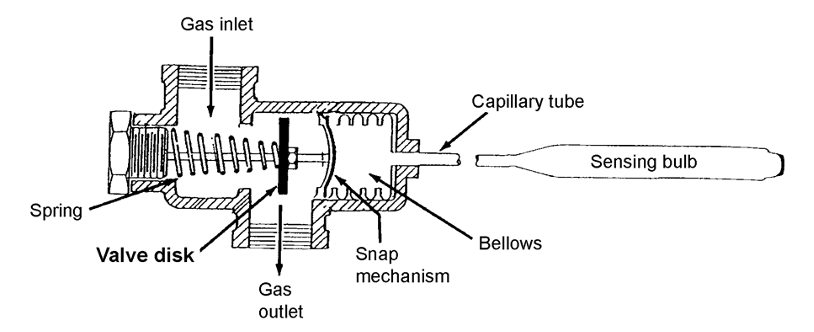
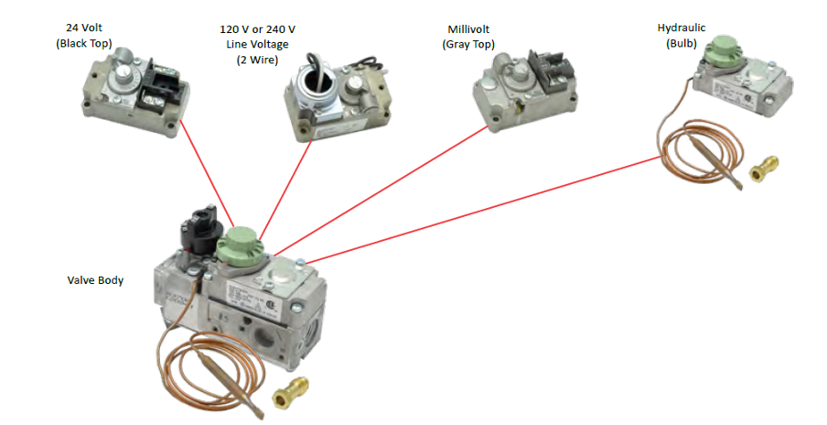
Figure 82 shows a common diaphragm operated control valve which can be supplied with different types of actuators, one of which is the hydraulic type which does not require a power source.
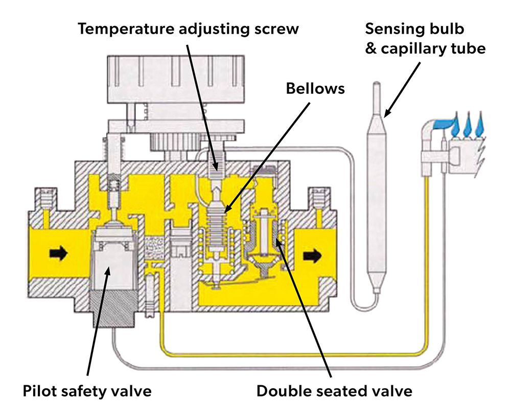
Besides snap-action where the valve is fully open or closed most valve manufactures also have modulating (snap-throttle, modusnap) types. Modulating hydraulic thermostat is similar to the snap-action, except that the valve initially snaps on and shuts off at a pre-set minimum input. If the temperature continues to drop the input will alter between full and minimum. Figure 83 shows the valve with the pilot safety valve being held open by the thermocouple. The temperature setpoint is satisfied so the double seated valve is closed.
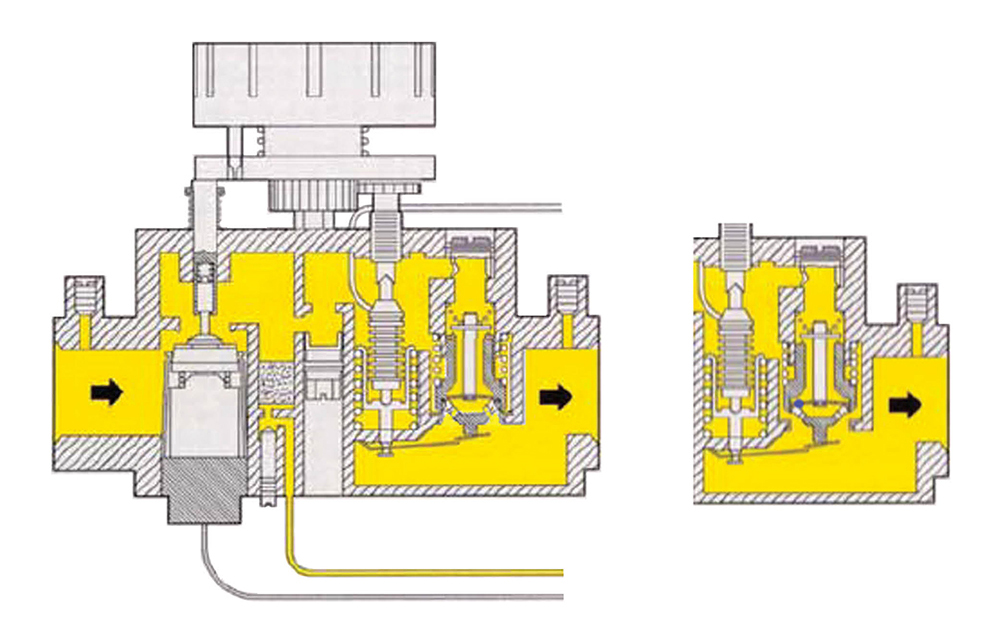
You can see in Figure 84 (left) the temperature has dropped below the temperature setpoint and the inner snap acting valve seat is in the open position. This inner seat supplies the minimum rate of gas flow, if the heating requirement is satisfied the temperature will rise and the valve will snap shut.
If more heat is required (right), the bellows continues to contract and the outer throttling valve seat is lifted to adjust the gas flow rate between the fixed minimum and full burner capacity.
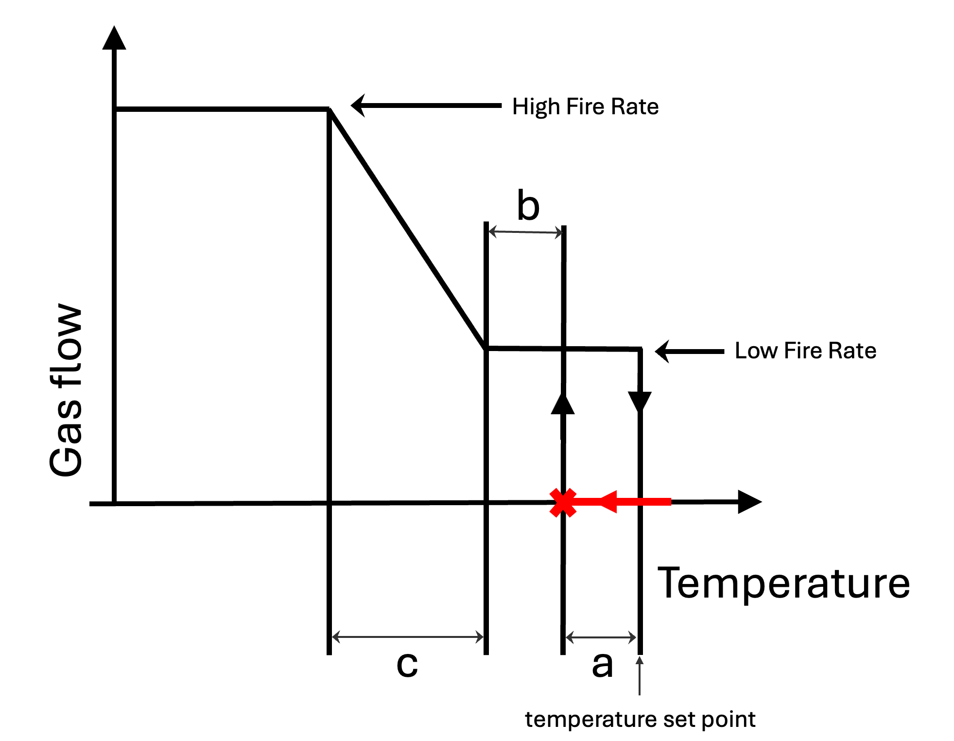
The gas flow and temperature settings have been plotted in Figure 85 to better understand the operating sequence:
- The red line on the temperature represents the temperature dropping below the setpoint. When it reaches the pre-set differential (a) below the setpoint the valve snaps open to the low fire rate.
- If the sensed temperature rises back up to the setpoint, the snap valve will close
- If the temperature continues to drop while at low fire, and gets to the pre-set differential (b) then the modulating seat begins to open increasing the flow proportionately (c) until the valve is fully open at high fire.
Hydraulic switches
Capillary temperature sensors are also used to operate electric switch’s on gas valve electric circuits. Figure 86 is an example of a hydraulically operated pilot safety switch. At first glance the sensing bulb and capillary tube look very similar to a thermocouple system. Upon closer inspection of the blow-up image of the gas valve you can see that the capillary tube is connected to a bellows. This is a 24 VAC standing pilot gas valve and the bellows holds in a pilot safety switch as long as the pilot is lit.
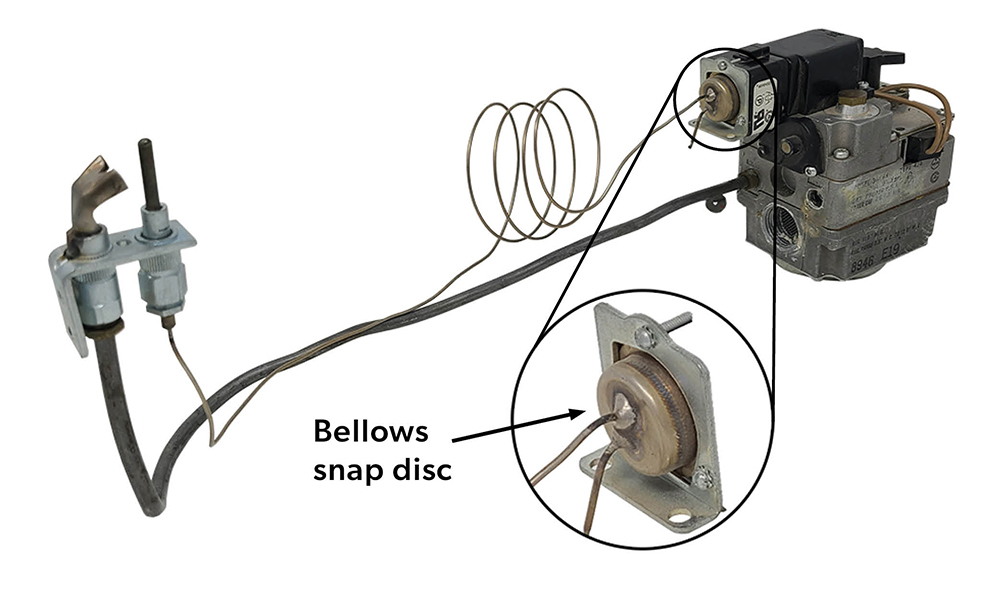
This is just one example, but capillary tube operated electric switches are also used as high limits and temperature control on millivolt and VAC operated gas valves.
Oven gas valves
Range oven gas valves are a hybrid of both electric and non electric operating components (Figure 87). The wiring of diagram of the 120VAC gas valve control circuit shows that the thermostat energizes both the hot surface Ignitor and the thermal bi-metal gas valve. The thermostat is a hydraulic bellows snap switch with a capillary tube leading to the sensing bulb located within the oven. Because the thermostat, HSI and gas valve are wired in series, meaning electricity must pass through the glow bar and then to the valve. The HSI blocks current to the gas valve through electrical resistance that declines as the igniter’s temperature rises. When the igniter reaches yellow heat, sufficient to ignite the gas, it allows passage of enough electricity to open the gas valve.
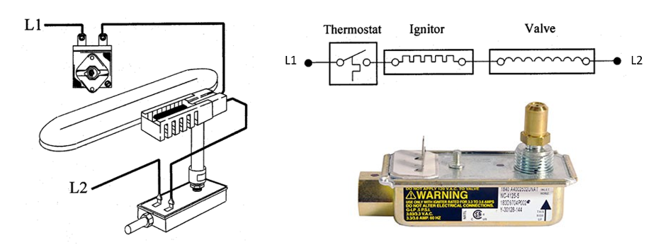
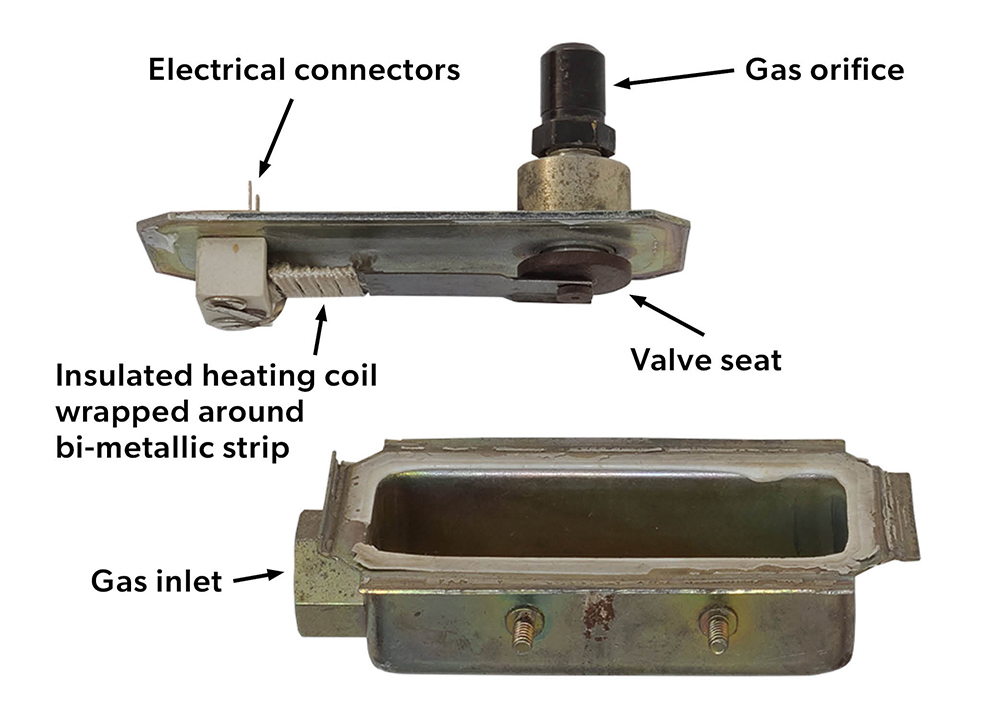
Inside the gas valve there is a bi-metal strip that lifts the valve disc from its seat when the bimetal is adequately heated by the insulated heating element wrapped around its base (Figure 88).
This simple circuit has a built-in safety in that, if the igniter is damaged the current will not get to the gas valve.
Seismic gas valve
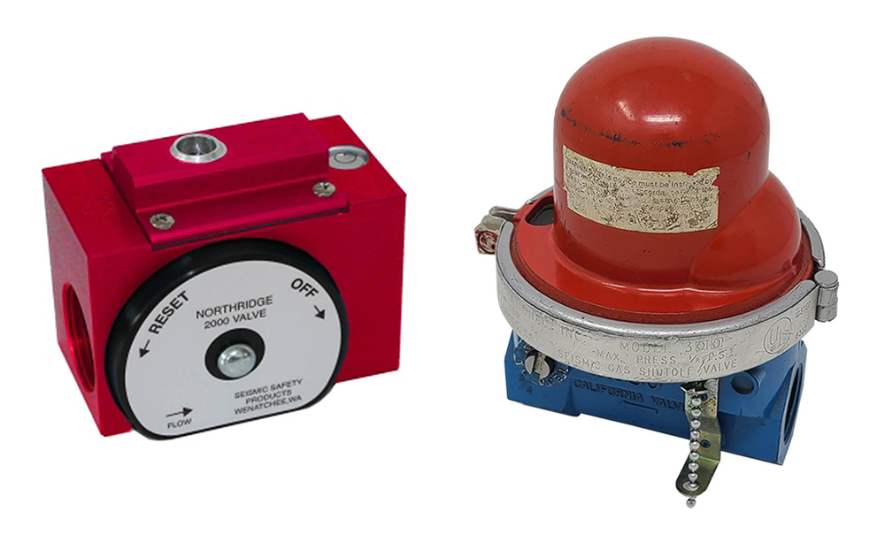
Seismic gas valves are a safety valve designed to shut off gas supply to a building during an earthquake. Figure 89 shows two popular models, both need to be installed level as they have an internal ball which moves when subject to horizontal vibration. They have an indicating window and must be manually reset once activated. When installing make sure to check the direction of flow.
Fire suppression gas valves
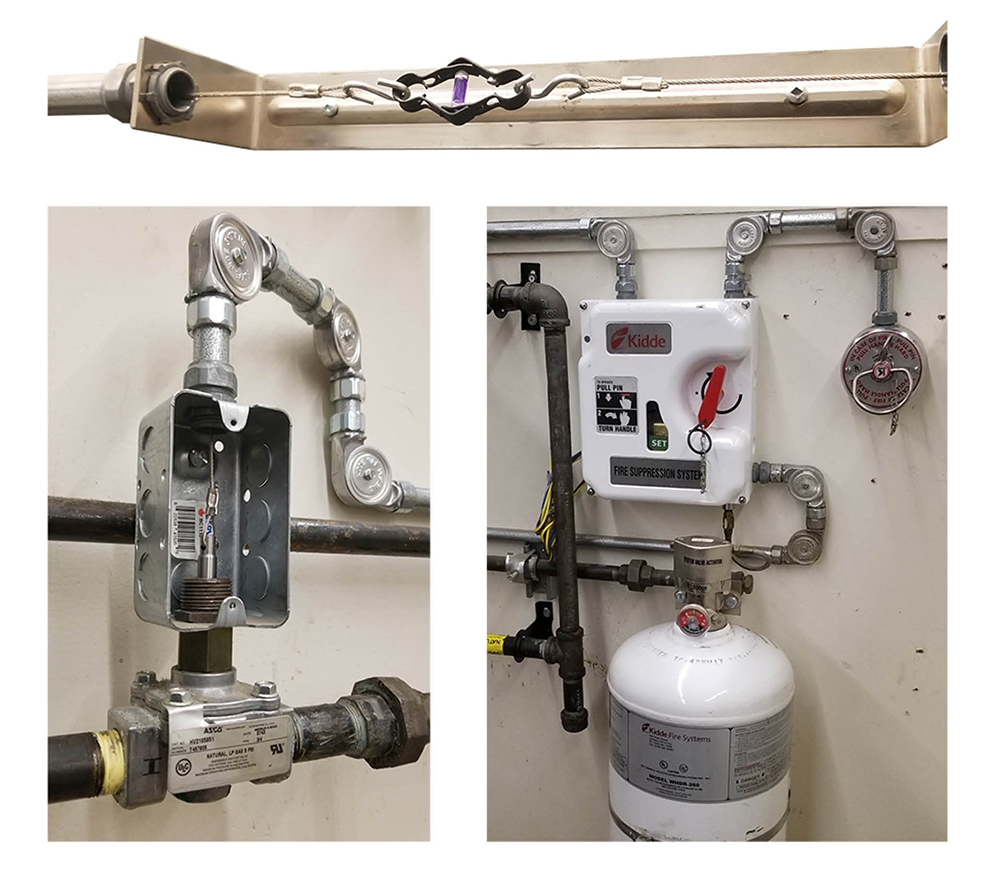
Commercial kitchen equipment with exhaust systems will have an automatic fire extinguishing system. The gas code requires, that any gas appliances protect or affected by the fire extinguishing system must be interlocked so the gas supply is shut off when the system is activated.
The gas shutoff valve must be resettable and located outside the protected area. The automatic fast closing valve may be either electrically or mechanically operated. Electrical types will be a typically solenoid valve, whereas the non-electric mechanical types will have cable activation system.
The cable system shown in Figure 90 has a spring loaded, release-to-close gas valve (bottom left) which is being held open by the cable which can be released by a manual pull station (bottom right) or a temperature activated fusible link located above the cooking equipment (top photo), either of which also releases the extinguishing agent onto the area.
 Now complete Self-Test 4 and check your answers.
Self-Test 4
Self-Test 4
Media Attributions
- Figure 41. “Solenoid valve” – The source for this image is unknown. It is being used for non-commercial, educational purposes. To receive credit for this image, please reach out to the publisher.
- Figure 42. “Pilot burner solenoid valve” by Rod Lidstone is licensed under a CC BY-NC-SA licence.
- Figure 43. “Automatic safety shut-off valve operation” – The source for this image is unknown. It is being used for non-commercial, educational purposes. To receive credit for this image, please reach out to the publisher.
- Figure 44. “Water heater combination gas valve” by Rod Lidstone is licensed under a CC BY-NC-SA licence.
- Figure 45. “1 ½” Diaphragm gas valve” by Rod Lidstone is licensed under a CC BY-NC-SA licence.
- Figure 46. “Diaphragm gas valve operation” – The source for this image is unknown. It is being used for non-commercial, educational purposes. To receive credit for this image, please reach out to the publisher.
- Figure 47. “Internal bleed diaphragm gas valve” from Robertshaw Controls Co. is used and adapted for educational purposes under the basis of fair dealing.
- Figure 48. “Millivolt combination gas valve” by Rod Lidstone is licensed under a CC BY-NC-SA licence.
- Figure 49. “1” Combination regulating diaphragm gas valve” by Rod Lidstone is licensed under a CC BY-NC-SA licence.
- Figure 50. “Servo diaphragm valve closed” – The source for this image is unknown. It is being used for non-commercial, educational purposes. To receive credit for this image, please reach out to the publisher.
- Figure 51. “Servo diaphragm valve wide open” – The source for this image is unknown. It is being used for non-commercial, educational purposes. To receive credit for this image, please reach out to the publisher.
- Figure 52. “Servo diaphragm valve throttling” – The source for this image is unknown. It is being used for non-commercial, educational purposes. To receive credit for this image, please reach out to the publisher.
- Figure 53. “Combination servo gas valve” from Honeywell International Inc. is used for educational purposes under the basis of fair dealing.
- Figure 54. “Redundant gas valve internal flow” from White-Rodgers and Emerson is used for educational purposes under the basis of fair dealing.
- Figure 55. “Universal combination redundant gas valves” from White-Rodgers and Emerson is used and adapted for educational purposes under the basis of fair dealing.
- Figure 56. “Compact direct ignition gas valve” from White-Rodgers and Emerson is used for educational purposes under the basis of fair dealing.
- Figure 57. “Double seated redundant gas valve internal flow” from White-Rodgers and Emerson is used for educational purposes under the basis of fair dealing.
- Figure 58. “Sealed combustion chamber pressures”.
- “Furnace Vent” (Left) – The source for this image is unknown. It is being used for non-commercial, educational purposes. To receive credit for this image, please reach out to the publisher.
- (Right) – The source for this image is unknown. It is being used for non-commercial, educational purposes. To receive credit for this image, please reach out to the publisher.
- Figure 59. “Combustion chamber reference tube”.
- (Left) – The source for this image is unknown. It is being used for non-commercial, educational purposes. To receive credit for this image, please reach out to the publisher.
- (Right) by Rod Lidstone is licensed under a CC BY-NC-SA licence.
- Figure 60. “Two stage redundant gas valve” from White-Rodgers and Emerson is used and adapted for educational purposes under the basis of fair dealing.
- Figure 61. “Modulating venturi burner”.
- “GB-WND 055 Functional Diagram” (Left) from DUNGS Combustion Controls is used and adapted for educational purposes under the basis of fair dealing
- (Right) – by Rod Lidstone is licensed under a CC BY-NC-SA licence.
- Figure 62. “Air supply connection” by Rod Lidstone is licensed under a CC BY-NC-SA licence.
- Figure 63. “Zero governor reference tube” by Rod Lidstone is licensed under a CC BY-NC-SA licence.
- Figure 64. “Modulating solenoid servo regulator” – The source for this image is unknown. It is being used for non-commercial, educational purposes. To receive credit for this image, please reach out to the publisher.
- Figure 65. “Stepper Combination Gas Valve” from White-Rodgers and Emerson is used for educational purposes under the basis of fair dealing.
- Figure 66. “Millivolt combination gas valve” by Rod Lidstone is licensed under a CC BY-NC-SA licence.
- Figure 67. “Millivolt pilot burner” by Rod Lidstone is licensed under a CC BY-NC-SA licence.
- Figure 68. “Millivolt gas valve wiring connections” – The source for this image is unknown. It is being used for non-commercial, educational purposes. To receive credit for this image, please reach out to the publisher.
- Figure 69. “Battery operated fireplace controls system” from SIT is used for educational purposes under the basis of fair dealing.
- Figure 70. “Standing pilot non-electric storage water heater gas valve components” by Rod Lidstone is licensed under a CC BY-NC-SA licence.
- Figure 71. “Rod and tube temperature sensor” by Rod Lidstone is licensed under a CC BY-NC-SA licence.
- Figure 72. “Rod and Tube operation” – The source for this image is unknown. It is being used for non-commercial, educational purposes. To receive credit for this image, please reach out to the publisher.
- Figure 73. “ECO cutaway” by Rod Lidstone is licensed under a CC BY-NC-SA licence.
- Figure 74. “TCO and wiring connections” by Rod Lidstone is licensed under a CC BY-NC-SA licence.
- Figure 75. “Self energized water heater gas valve” by Rod Lidstone is licensed under a CC BY-NC-SA licence.
- Figure 76. “Separated major components” by Rod Lidstone is licensed under a CC BY-NC-SA licence.
- Figure 77. “Two common models of electric storage water heater gas valves” by Rod Lidstone is licensed under a CC BY-NC-SA licence.
- Figure 78. “Disassembled electric gas valve” by Rod Lidstone is licensed under a CC BY-NC-SA licence.
- Figure 79. “FV sensor” by Rod Lidstone is licensed under a CC BY-NC-SA licence.
- Figure 80. “Honeywell connection diagram” from Honeywell International Inc. is used for educational purposes under the basis of fair dealing.
- Figure 81. “Capillary tube valve components” – The source for this image is unknown. It is being used for non-commercial, educational purposes. To receive credit for this image, please reach out to the publisher.
- Figure 82. “Actuator options” from Robershaw is used for educational purposes under the basis of fair dealing.
- Figure 83. “Modulating hydraulic valve closed position” from SIT is used for educational purposes under the basis of fair dealing.
- Figure 84. “Hydraulic Modulating valve, left low fire, right throttling” from SIT is used for educational purposes under the basis of fair dealing.
- Figure 85. “Snap/modulating gas flow” by BCcampus is licensed under a CC BY-NC-SA licence.
- Figure 86. “Capillary pilot safety” by Rod Lidstone is licensed under a CC BY-NC-SA licence.
- Figure 87. “Range oven and broiler gas valve”.
-
“Robertshaw Y-75001-AF12” (Bottom right) from Robertshaw is used for educational purposes under the basis of fair dealing.
- (Left) and (top right) by Rod Lidstone is licensed under a CC BY-NC-SA licence.
-
- Figure 88. “Oven gas valve internal components” by Rod Lidstone is licensed under a CC BY-NC-SA licence.
- Figure 89. “Earthquake valves” from Seismic Safety Products is used for educational purposes under the basis of fair dealing.
- Figure 90. “Kitchen exhaust fire extinguishing system” by Rod Lidstone is licensed under a CC BY-NC-SA licence.
Image Description
Figure 53. “Combination servo gas valve” image description: A labeled diagram of a combination servo gas valve, with its main components identified in a clockwise direction starting from the top:
- Control knob (pilot on/off)
- Servo pressure regulator
- Bleed vent
- Servo regulator diaphragm
- Servo regulator valve
- Servo regulator pressure chamber
- Valve operator on/off lever (solenoid operated)
- Evacuation channel
- Pilot gas
- Gas outlet
- Working gas chamber
Continuing clockwise along the bottom of the regulator:
- Working gas pressure chamber
- Main valve diaphragm
- Main valve
- Safety valve
Finally, moving up the left side of the diagram:
- Gas inlet
- Power unit (safety shut-off) [Return Figure 53]
Figure 57. “Double seated redundant gas valve internal flow” image description: A numbered diagram with a corresponding list as follows:
- Valve solenoid
- Pressure tap inlet
- Redundant valve
- Main valve
- Supply inlet
- Diaphragm
- Regulator valve
- Main burner outlet
- Servo regulator
- Regulator adjust screw
- Pressure tap outlet
- Working gas orifices [Return to Figure 57]

