Competency B3: Commission Fuel Gas Delivery Systems
Learning Task 1
Describe Gas Piping and Tubing Pressure Testing
After installing a gas piping system, you must pressure test it. If any section of the piping system is to be enclosed or concealed a test must be performed before closing it in. To test for tightness, the piping may be filled and pressurized with air or inert gas. Never use oxygen for testing. Oxygen will combine with oils and spontaneous combustion will take place.
Gas code test requirements
The CSA B149.1 Gas installation code specifies the pressure test requirement for piping and tubing systems extending from the termination of the utility installation or from the distributor’s propane tank. The Section 6 pressure test table stipulates the required test pressure and duration based on the systems working pressure, size, and length.
For example by referencing the code table we find that, a 2-psi system 50 meters in length will require a 15-psi pressure test for a minimum of 15 minutes. Whereas a 2-psi system 70 meters in length will require a 15-psi pressure test for a minimum of 60 minutes.
Equipment
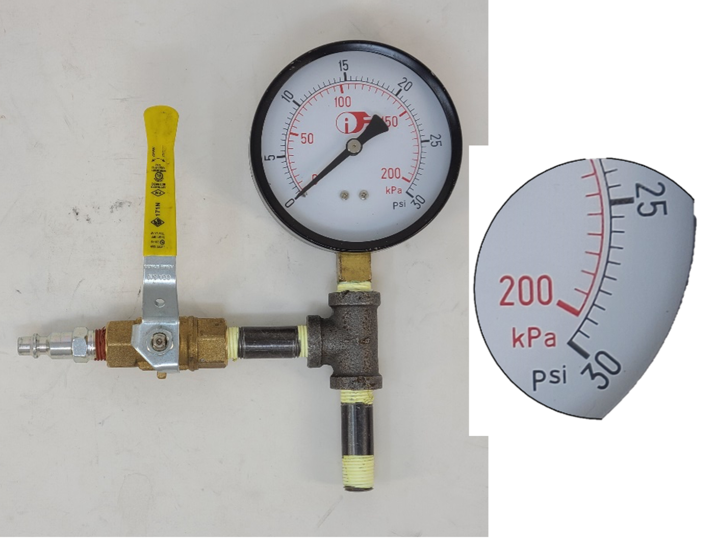
For an air test, you can pressurize the piping system by using a hand pump or an air compressor. When performing an inert gas pressure test use a pressure regulator and pressurized gas cylinders. Temporary test connection piping, fittings, hoses will need to be connected and must include an isolation valve and the appropriate test gauge.
The pressure gauge, must be a minimum of 3 in. (75 mm) diameter and the maximum range must exceed the test pressure by at least 15% but not more than 300%. The pressure increments of the gauge or equivalent device shall not be greater than either 2 psig (14 kPa) or 2% of the maximum dial reading of the gauge, whichever is less. For example, a test gauge to administer a 15 psi test could not have a maximum range of at least 17.25 psi and not more than 45 psi. The 30 psi gauge shown in figure 1 would be ok to use as its increments are 0.5 psi and the maximum increment size for a 30 psi gauge must be 0.6 psi (30 psi x2%). This follows the rule of thumb: your test pressure should fall in the middle third of your gauge.

Test Procedures
During installation of piping and tubing and before pressure testing, visually inspect piping and tubing for cuts, abrasion, and any other defect that may cause leaking or failure of the system when it is under pressure. As stated the gas piping must pressure tested after being installed and:
- before connecting of any appliances (stage 1)
- after the appliances are connected prior to operation (stage 2)
Prior to connecting the appliances
Perform the first pressure test after the installation of the piping system and before the connection of any appliances to the system. Before testing, isolate or remove any components of the system that have a pressure rating below the test pressure to prevent any damage to these components. For example, a line pressure regulator usually does not have a high enough pressure rating to be included in the pressure test.
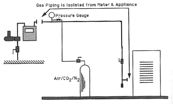
Follow these steps to perform the stage 1 test (Figure 2):
- Isolate the piping system or section that you will test by capping or plugging all open ends.
- Insert a pressure gauge at one end of the system. Include a separate shutoff valve at the gauge connection so the pressure supply hose can be removed.
- Pressurize the system with air or inert gas (nitrogen or carbon dioxide) to the specified test pressure.
- Monitor the pressure for the specified minimum duration. Be conscious of any temperature changes that will affect the pressure reading. If a pressure recorder is used it must be calibrated to the same increment requirements as the pressure gauge.

If a drop in pressure is noticed, you will need to search for the location of the leak, typically with a soap solution leak detector.
Inert gas volume requirements
Most often for smaller pipe sizes the pressure test will usually use readily available compressed air. Larger commercial and industrial system will often use inert gas for the pressure test as it is also required for the purging procedure. If an inert gas is used you will need to determine the number of cylinders of compressed. gas that are required. A typical cylinder, about 5′ tall (Figure 3), can hold about 230 cubic feet of nitrogen gas at atmospheric pressure, if it is filled to the maximum operating pressure of 2200 psig. Although this volume will be reduced based on the system test pressure being used.

Using Boyles’ Law we can determine the reduced volume of gas available for a 15 pisg (approx. 30 psia) pressure test.
Example:
[latex]\begin{array}{rcl} P_1 V_1 &=& P_2 V_2 \\ 14.37 \times 230 &=& (14.73 + 15) V_2 \\ \dfrac{3387.9}{19.73} &=& V_2 \\ V_2 &=& 171.7\text{ ft}^3 \end{array}[/latex]
Given that every 1 foot length of 2” pipe only has a volume of .022 ft3, one cylinder will be more than adequate for pressure testing a typical residential gas system. For larger and longer piping systems with higher test pressures additional cylinders may be needed, especially when additional volumes are required for purging operations.
After the appliances are connected
After the gas appliances are installed, perform the Stage 2 test (Figure 4):
- Install a pressure gauge or manometer at the gas meter outlet, include a bleed valve at the gauge connection. The manometer or pressure gauge that you used for this test should be in 1 in. w.c. (250 kPa) increments or less. If the system has any line pressure regulators, addition pressure gauges or manometers should be connected to check the regulator setpoint and lock-up pressures.
- Visually check the entire system to ensure that all openings have been connected, the appliance shut-off valve is open, the appliance control valve is closed, and the gauge bleed valve is closed.
- Slowly open the meter valve and listen for the gas flow to stop. Monitor the gas meter test dial to ensure that no gas is escaping which would indicated an opening or large leak.
- At this time the service and line pressure regulators’ static pressures should be checked to ensure the outlet pressure lockup settings are not being exceeding, as this could damage downstream components.
- Turn off the meter valve to capture the gas under pressure (Figure 3). The gas pressure indicated on the manometer, or pressure test gauge, must be maintained for a minimum of 10 minutes.
- Upon successfully completing the 10 minute pressure test, perform a leak test on all untested control valves and appliance piping using non-corrosive bubble leak detector solution under normal operating pressure to ensure they are gas tight.
- Finally check to ensure there was no meter valve seepage that may have masked a system leak. The valve may be seeping gas as a result of dried and hardened valve grease. With the static pressure still captured in the system, and the meter valve turned off, release a small amount of gas through the gauge test assembly bleed valve to drop the pressure slightly. If after this action the gas pressure increases slowly the meter valve is seeping gas. The meter valve will need to be service before the stage two test is repeated.

Propane system tests
On propane systems the test before the installation of the appliances is performed in the same way as for natural gas.
The test after the appliances are connected will differ for separate, two stage regulation systems. Additional pressure gauges or manometers will be required as both pressure stages must get a 10-minute static pressure test and a valve seepage test.
Leak detection
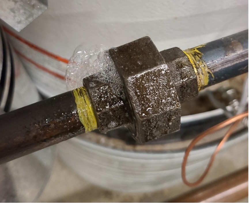
The best way to search is by using a bubble leak detector solution (aka soap test). A leak will cause the solution to create bubbles (Figure 4) at the joint or fitting. Specially designed bubble leak detector solutions that are made for this purpose are recommended. They have better coating and bubbling characteristics than dish detergent and are non-corrosive. Sometimes the location of the leak may be obvious, but other times it will not (Figure 5). In those cases, you will need to cover as many of the fitting joints with the solution as possible to locate the potential leak(s). Be aware of the test pressure as you may need to add additional pressure to the lines to make up for leak loss.

It is important to thoroughly examine the leaking joint once it has been located. The type of connection may play a big role in the cause of the leak. While it is possible that a fitting is simply loose, there are several other possibilities including a crack in a pipe, bad threads, a poor flare when dealing with copper lines, or even a bad seal due to a poorly cut CSST gas line. Make sure to bleed off the pressure before fixing a leak. Once the leak has been repaired you must repeat the pressure test. Clean up any leak detector residue with a wet rag when you have completed the tests.
Final leak tests
Any temporary test connections points must be plugged or caped and soap tested. Additionally, when the appliance is started all valve train connections downstream of the control valve must be soap tested.
 Now complete Self-Test 1 and check your answers.
Self-Test 1
Self-Test 1
Media Attributions
- Figure 1. “Pressure test assembly” by Rod Lidstone is licensed under a CC BY-NC-SA licence.
- Figure 2. “Stage 1 pressure test” by Rod Lidstone is licensed under a CC BY-NC-SA licence.
- Figure 3. “Nitrogen cylinders” by Rod Lidstone is licensed under a CC BY-NC-SA licence.
- Figure 4. “Stage 2 pressure test” by Rod Lidstone is licensed under a CC BY-NC-SA licence.
- Figure 5. “Leaking joint” by Rod Lidstone is licensed under a CC BY-NC-SA licence.

