Competency B4: Install Air Supply Systems for Fuel Gas Appliances
Learning Task 3
Describe The Installation of Passive Air Supply Systems
As the qualified piping tradesperson you are ultimately responsible for all aspects of the installation required to ensure the safe operation of the gas appliance. Depending on the type of building, the ductwork for the air supply and ventilation air will most often be perform by a qualified Sheet Metal Tradesperson working under your installation permit.
Low volume air supply ducting
The passive air supply inside termination must be located within 2 ft (600 mm) horizontally and not more than 1 ft (300 mm) above, the burner level of the gas appliance (Figure 11). If there is more than one gas appliance in the area, the air supply will be located at the one with the largest input. This ensures that the air supply is dedicated to the appliance(s) served and will not be influence from other equipment in the structure that also need outside air.
For low volume installations the inlet opening from outside must be at least 24 in. (600 mm) between the bottom of the intake grill and the finished grade. This height is necessary to prevent air flow obstruction by snow or other materials. This height requirement is a variation for the Province of BC, as the National Code stipulates a 12 in. minimum.
The air supply will be provided by a duct, unless a wall opening can be located such that it is close enough to meet the termination location requirements.
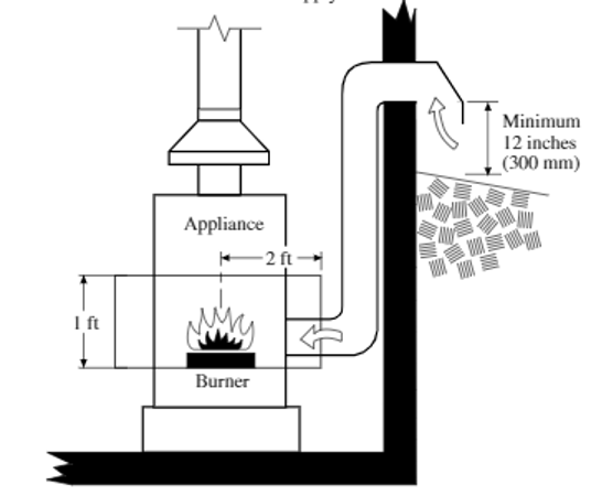
Make sure that the air supply does not come from an area that contains air borne contaminants such as swimming pools, vehicle exhaust fumes, or laundry facilities. Additionally the Gas Code states that the air supply inlet opening shall not be located within 3 feet (1 m) of a moisture exhaust duct, such as clothes dryer discharge or spa exhaust.
High volume air supply ducting
As was previously discussed high volume installations require both an air supply and ventilation air openings into the mechanical room.
Recall that when any of the gas appliances in the room are equipped with draft control devices the air supply shall be located not less than 6 in. (150 mm) or more than 18 in. (450 mm) above the mechanical room floor. Whereas if none of the gas appliances are equipped with draft control devices then the air supply opening may be located anywhere in the mechanical room, if it does not interfere with the performance of the ventilation air opening (Figure 12).
The primary form of interference to be avoided involves the short circuiting of airflow, which could occur when ventilation and air supply openings are placed near to one another at the same level or on opposite walls at building corners where they are susceptible to wind suction effects. Locating the air supply opening below the ventilation air opening will assist proper air circulation.
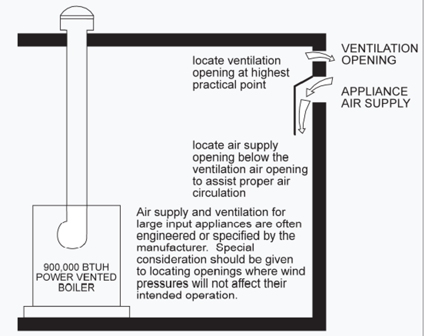
Whether or not you require ducting and how much will depend on the structure of the building and the appliance layout. For example, the mechanical room may be below grade, which could require both internal and external ducting. The design of the air supply and ventilation system for large volume installations is often engineered or specified by the equipment manufacture but these must still be approved by the BC authority having jurisdiction.
Duct installation
All duct work must be of metal or a material that meets the National standard (CAN/ULC-S110), requirements for materials used to fabricate air duct systems. These ducts are typically installed using rectangular or round galvanized sheet metal. As was seen on the Gas Code low volume sizing tables, the free area values are used to calculate the necessary rectangular duct dimension, and the round duct equivalent values can be used to select the appropriate round duct size.
Rectangular and square ducts have higher friction resistance to airflow than round ducts.
Square or rectangular ducts with dimension less than 3 in. cannot be used as the turbulence generated will significantly affect the free flow of air. For this reason, round ducts must always be used when the required free area is less than 9 in.2.
When the outside air supply enters the mechanical room, it must be located to avoid any problems that could result from cold air contacting piping, electrical, or mechanical equipment. The duct itself should also be suitably insulated and provided with a vapour barrier, to avoid condensation on its surface.
When air supply is brought to the appliance using the duct method, the overall length of duct as well as any changes of direction or other restrictions must be taken into consideration. When selecting the route for the duct every attempt should be made to limit the length of the duct and thus also limiting the air flow restriction. The required free area sizes listed in the Gas Code tables are based on a maximum equivalent duct length of 20 ft. If the length needs to exceed 20 ft of equivalent length the required size can be increase by one size to compensate for increased pipe friction losses. When increasing by one pipe size the new maximum equivalent length is 50 ft. In cases were the duct must exceed an equivalent length of 50 ft, a mechanical air supply would be required.
Equivalent Length or Effective Length
Just as with piping systems and process fluids, duct fittings will add resistance to air flow. There are many manufacture and engineering tables available that quantify the friction loss created by the different fitting configurations. It is common to express the amount of resistance that a fitting creates as the equivalent length of straight pipe that would create the same pressure loss. The equivalent length of the fittings used gets added to the actual lengths of straight pipe to conclude the total equivalent length of the duct system. The sum of the straight lengths and the fitting equivalent lengths is also be referred to as the effective length of the duct.
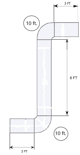
Duct fitting equivalent lengths values vary for such things as; square, round, material type, angle, radius. For the example shown in Figure 13 we have used an equivalent of 10 ft for each 90 elbow which is a common value for 90-degree elbows. Assuming the louver that gets used is over sized to give the necessary equivalent free are of the duct we will not need to compensate for it. Therefore, lengths of the straight duct plus the equivalent length of the two elbows would give us an effective duct length of 34 ft Because the effective length of the duct is greater than 20 ft the size of the duct will need to be increased by one size over that required by the Code tables.
Duct assembly
On residential and small commercial installations prefabricated galvanized sheet metal duct materials are often used.
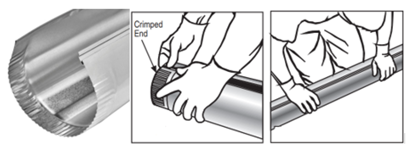
Round duct pipe and fittings come with crimped ends for easy assembly. They have a longitudinal snap lock seam. By shipping and storing pipe with the seam unconnected, multiple pipes can be nested within each other.
To create finished pipe lengths, start at the crimped end and snap the two sides together (Figure 14). Hold together with one hand and move down the pipe as the seam snaps in. When you get halfway, it should snap fully closed.
Round duct sections are fastened together or to fittings with self-tapping screws. This crimp connection makes a nearly air tight connection. If further sealing is needed the joint can be taped but this is not usually need for low pressure air supply applications.
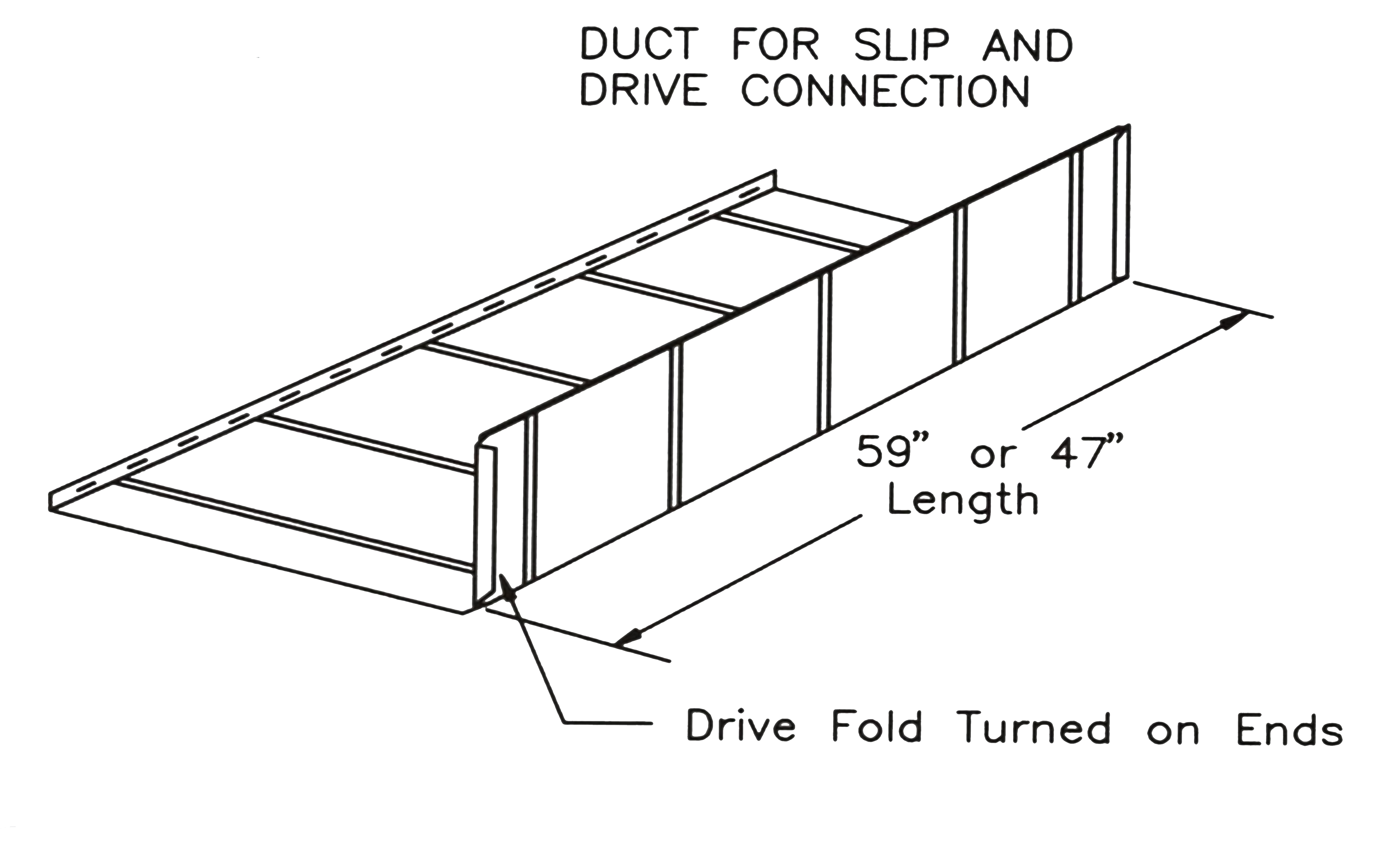
Pre-manufactured rectangular ducts are shipped in two L- shaped half sections (Figure 15). They are available in various lengths, 60 in. being most common. The two L-shaped half section are assembled using the two longitudinal button snap lock seams. Notice the two short sides have their ends turned over to create a Drive (hem)fold. Whereas the two long sides have raw edges.
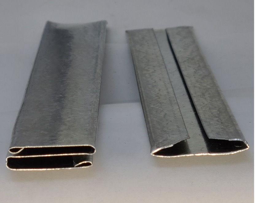
The standard means of connecting two assembled rectangular duct sections end to end (transverse joint) is to use sleeves of galvanized sheet metal called S-Cleats (Slip) and Drive Cleats (Figure 16). The drive cleat on the right has its two inside corners trimmed off. This will make it easier to get it started onto the two duct hems.
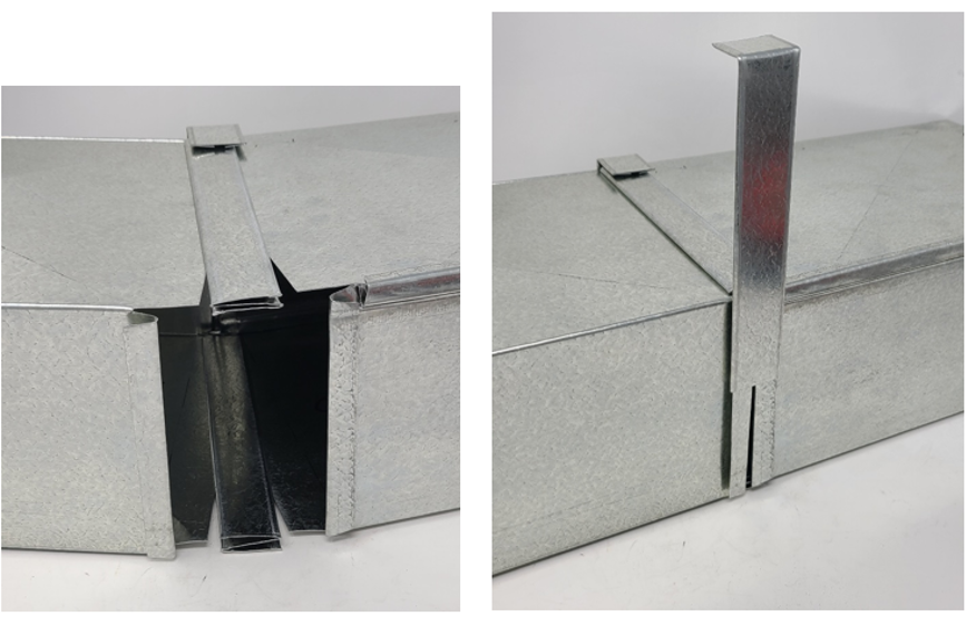
You can see in Figure 17 the S-Cleats are used to connect the long side of the duct with the raw edges overlapped and slipped into the cleats. The drive cleats are used to pull together the two sections by hammering the Drive Cleat onto the two mated hemmed edges. Notice the Drive cleat has been cut to the approximate length and one end has already been bent over.
Terminations
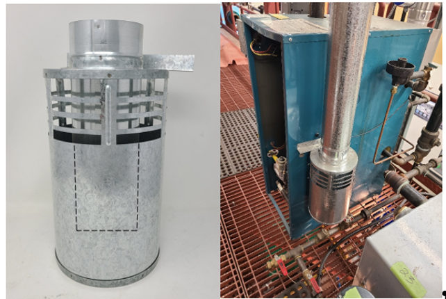
The Code requirements for the inside duct terminal locations of both low and high volume have previously been identified. As was also mentioned, in cold climates you may want to provide insulation and a vapor barrier to minimize condensation on the outside surface of the duct. If cold air becomes a comfort problem, certified automatic and interlocked dampers are also available, which only open when the appliances are operating. You can also install a passive air trap on the inside termination. The air trap is designed to use the different in buoyancy force of inside and outside air temperature, to inhibit the unwanted movement of air through the duct. The most common type is called a combustion air pot or bucket (Figure 18). A dotted line has been added to the picture (left), to show how the duct extends down into the bucket. Once the lower portion of the bucket fills with cold air it will not flow upward into the room until it is draw out of the bucket by a slight negative pressure being created when the appliance draws air from the room.
The outside termination clearance requirements related to finished grade and air contaminant have been previously discussed. Some addition outside termination considerations include flue gas vents, and gas regulator vents including gas meters. The clearance requirement from the air supply to vents and regulators are found within those sections of the Code book.
The minimum clearance requirements for a flue gas vent to a passive air supply opening are:
- 6 in. (150 mm) for inputs up to and including 10000 Btuh (3 kW);
- 12 in. (300 mm) for inputs from 10000 Btuh (3 kW) up to and including 100000 Btuh (30 kW);
- 3 ft (900 mm) for inputs exceeding 100000 Btuh (30 kW)
These listed inputs are from the vented appliance.
The minimum clearance requirements for a gas regulator vent (including meter service regulator) to an appliance air supply are:
- 3 ft (1 m) for a vent serving a natural gas regulator
- 10 ft (3 m) for a vent serving a propane regulator
The Gas Code allows for a clearance reduction to 1 ft (300 mm) for natural gas regulators, which have a certified internal device that restricts the rate in which gas can be expelled form the vent. See the code for the specific requirements
The building envelop penetrations must be properly sealed to maintain the exterior seals and vapor barrier.
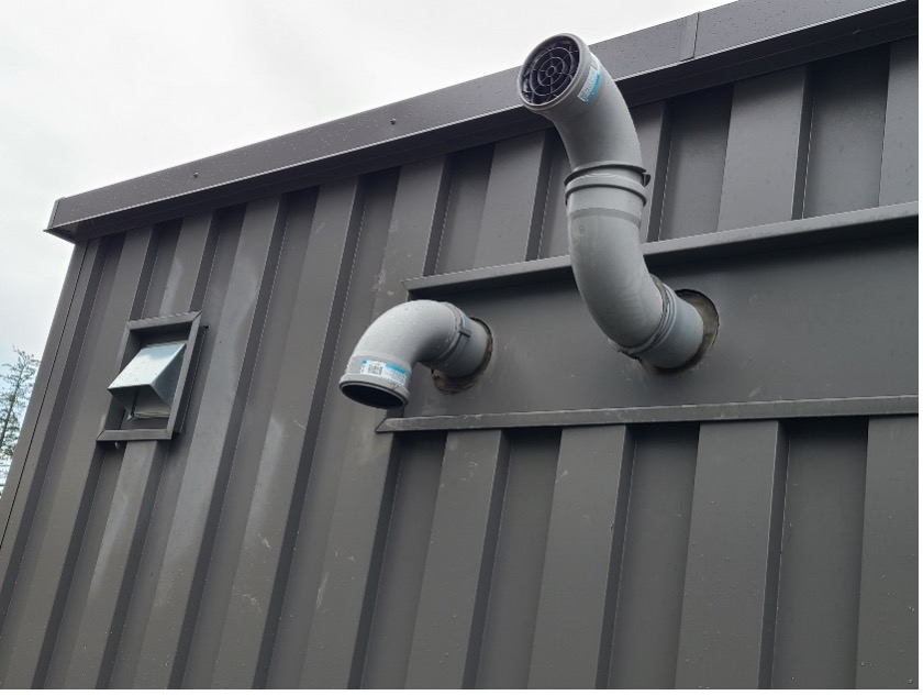
All direct vent appliances must have their air supply and vent piping terminations conform to the Gas code clearances as well as the manufactures instructions (Figure 19).
 Now complete Self-Test 3 and check your answers.
Self-Test 3
Self-Test 3
Media Attributions
- Figure 11. “Passive air supply terminations” – The source for this image is unknown. It is being used for non-commercial, educational purposes. To receive credit for this image, please reach out to the publisher.
- Figure 12. “Outside air openings for large volume power burner” – The source for this image is unknown. It is being used for non-commercial, educational purposes. To receive credit for this image, please reach out to the publisher.
- Figure 13. “Effective duct length” by Camosun College is licensed under a CC BY-NC-SA licence.
- Figure 14. “Round duct assembly” by Camosun College is licensed under a CC BY-NC-SA licence.
- Figure 15. “Rectangular duct half section” from ECCO Manufacturing is used and adapted for educational purposes under the basis of fair dealing.
- Figure 16. “S-Cleat and Drive Cleat” by Camosun College is licensed under a CC BY-NC-SA licence.
- Figure 17. “Assembling Slip & Drive Duct” by Camosun College is licensed under a CC BY-NC-SA licence.
- Figure 18. “Combustion air pot/bucket” by Camosun College is licensed under a CC BY-NC-SA licence.
- Figure 19. “Direct vent terminations” by Camosun College is licensed under a CC BY-NC-SA licence.

