Competency B2: Install Regulators, Valves, and Valve Train Components
Learning Task 2
Installing Gas Pressure Regulators
Although this learning task focuses on the physical act of installing regulators it is critical that the proper regulator has been chosen for the application. Future studies will explain the factors and procedures for gas regulator selection and sizing.
For a gas regulator to perform as expected you must install it properly in the piping system. The installation must meet the requirements of the Gas Code and conform to manufactures installation instructions. To ensure that the regulator is installed properly, the installation process must be properly planned.
Here are some common Gas Code terms that will also be used in this learning task.
- Accessory — a part capable of performing an independent function and contributing to the operation of the appliance that it serves.
- Bleed vent — a vent where the expiration or inspiration of air or gas occurs from or to one side of a diaphragm of any accessory, component, or equipment such as a valve, pressure regulator, or switch.
- Vent limiter – A means that limits the flow of gas from the atmospheric diaphragm chamber to the atmosphere in the event of a diaphragm rupture. This may be either a limiting orifice or a limiting device.
- Certified — investigated and identified by a designated testing organization as conforming to recognized standards, requirements, or accepted test reports.
- Component — an essential part of an appliance or equipment.
- Concealed piping or tubing — piping or tubing that, when in place in a wall, floor, or ceiling of a finished building, is hidden from view and can only be exposed by use of a tool. The term does not apply to piping or tubing that passes directly through a wall or partition.
- Overpressure protection device — a device that under abnormal conditions will act to reduce, restrict, or shut off the supply of gas flowing into a system to prevent gas pressure in that system from exceeding the rated pressure of the system components.
- Readily accessible — capable of being reached quickly for operation, renewal, servicing, or inspection, without requiring climbing over, or the removal of, an obstacle or the use of a portable ladder.
- Relief device — a device designed to open to prevent a rise of gas pressure in excess of a specified value due to an emergency or abnormal conditions.
- Internal relief valve — a pressure relief valve that is built into the body of the diaphragm assembly of a pressure regulator.
- Line relief valve — a relief valve installed in the piping or tubing system downstream of a final-stage pressure regulator that is not equipped with an internal relief valve.
- Ventilated space — a space where there is an air change by means of natural ventilation or mechanical means, or where the space communicates with the rest of the structure by means of permanent openings.
Over Pressure Protection
Any time a pressure reducing regulator is installed that supplies gas from any system to another system with a lower maximum allowable operating pressure some form of over pressure protection (OPP) is required to protect the downstream components.
The gas code stipulates that, for piping systems with a supply pressure over 2 psi, a line pressure or high pressure regulator must be provide with OPP.
The gas code identifies the following methods of OPP:
- Overpressure relief device — an overpressure protection device that functions by discharging gas from the downstream system.
- Monitoring regulator — an overpressure protection device that functions as a second gas pressure regulator in series with the primary gas pressure regulator.
- Overpressure shut-off device — an overpressure protection device that functions by completely shutting off the flow of gas into the downstream system.
Relief devices
A relief valve is a device that vents process fluid to atmosphere to maintain the pressure downstream of the regulator below the safe maximum pressure. Relief valve exhaust must be directed or piped to a safe location. The basic types of relief vales are:
- Pop types
- Direct operated relief valves
- Internal relief
- Pilot operated relief valves
Pop-type
The pop type relief valve is the simplest form of relief (Figure 9). When the pressure increases above the set pressure the pop relief valves will go to the wide-open position until the overpressure condition is reduced. This type of relief valve is almost exclusively used by natural gas distributors upstream of the building meter set.

Direct operated
Direct-operated relief valves provide throttling action and require less pressure buildup to open than the pop-type. A direct operated relief valve looks like an ordinary direct-operated regulator except that it senses upstream pressure rather than downstream pressure. And, it uses a spring-to close rather than a spring-open action.
It contains the same essential elements as a direct-operated regulator:
- A diaphragm that measures system pressure
- A spring that loads downward force onto the diaphragm and determines the relief setpoint
- A valve that throttles the relief flow

Direct-operated relief valves are commonly used in natural gas systems supplying commercial enterprises such as restaurants and laundries, and in industry to protect industrial furnaces and other equipment. The relief valve assembly is located in the center of the regulators diaphragm.
Internal relief
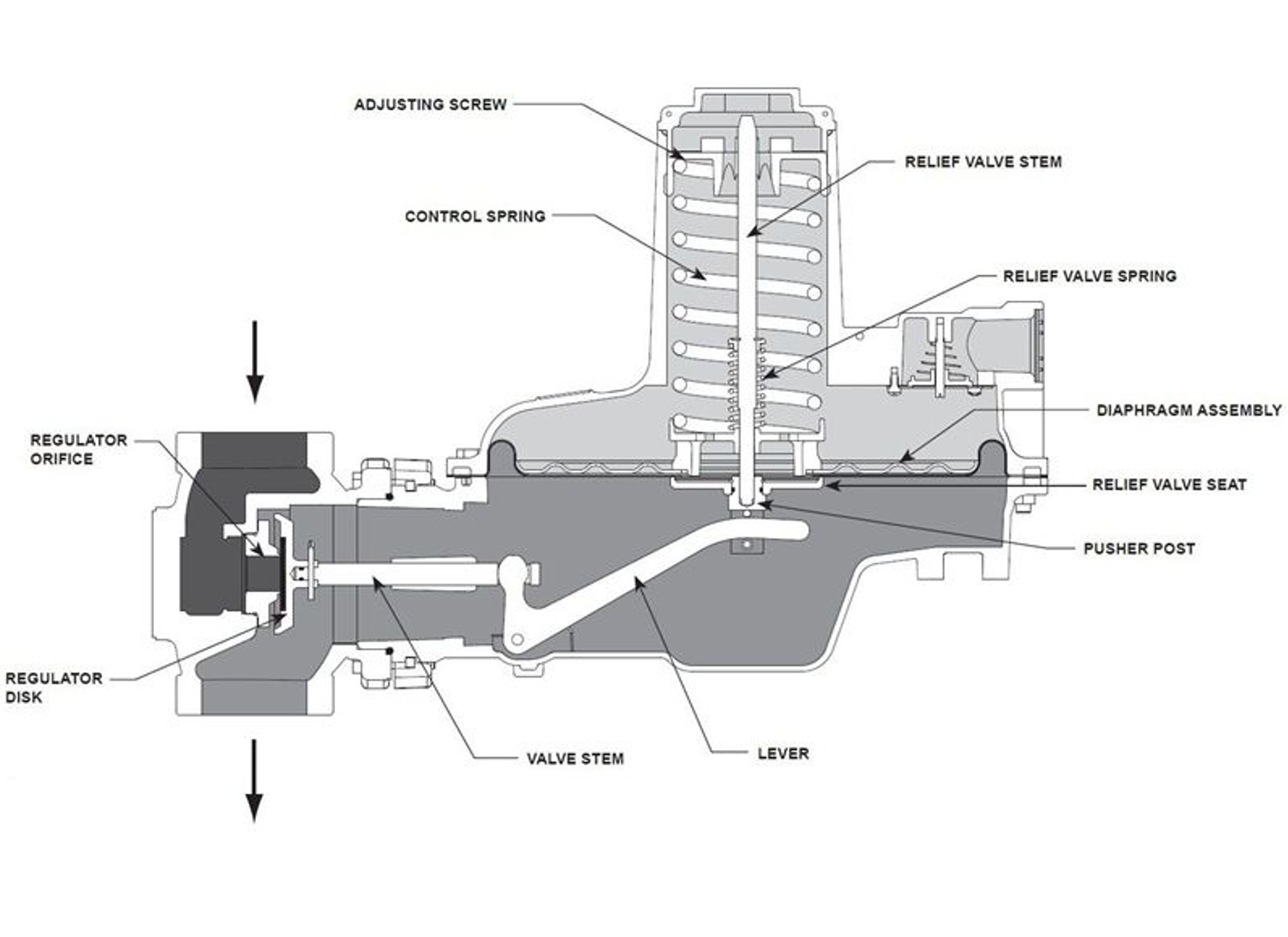
Internal relief is a type of direct relief valve that is built into the body of a pressure regulator. Regulators that include internal relief valves may eliminate the requirement for external overpressure protection.
When an overpressure condition develops, the downstream pressure lifts the main diaphragm until the relief valve seat comes in contact with the pusher post (Figure 11). At this point, any increase in downstream pressure compresses both the main and relief loading springs. When sufficient force is applied, the main diaphragm and the relief valve seat will separate and allow gas flow to pass through the centre opening in the diaphragm to the relief valve opening.
Pilot operated
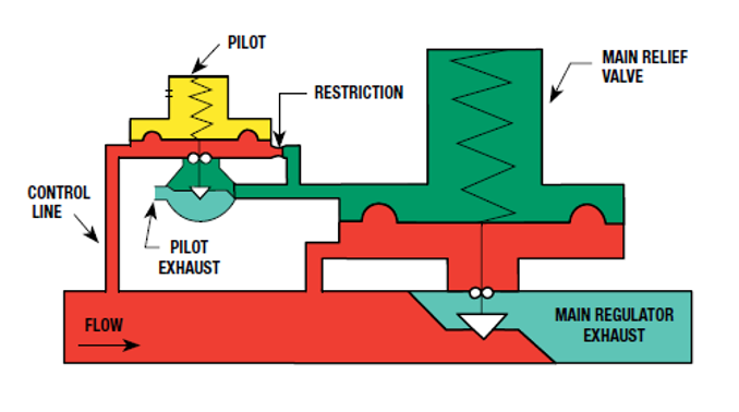
Pilot-operated relief valves have two direct-operated relief valves; a pilot and a main relief valve. The pilot relief increases the effect of changes in inlet pressure on the main relief valve. The pilot-operated relief valves have the most accuracy, but are also the most complicated and expensive type of relief. They are typically found on applications requiring high capacity and low pressure buildup.
During normal operation, the pilot is closed allowing loading pressure to register above the main relief valve’s diaphragm. This pressure is opposed by inlet pressure acting on the bottom of the diaphragm.
If inlet pressure rises above setpoint, the pilot valve opens, exhausting the loading pressure. If loading pressure is reduced above the main relief valve diaphragm faster than it is replaced through the pilot fixed restriction, loading pressure is reduced and inlet pressure below the diaphragm will cause the main regulator to open.
When a pressure regulator has internal relief or a pressure relief valve is used, they must be vented to the outdoors to a safe location.
Monitoring regulator
Over pressure protection by monitoring is also called pressure limiting. Pressure limiting is overpressure control by containment as there is no venting to atmosphere required. The gas code defines OPP by monitoring regulator as a second gas pressure regulator in series with the primary gas pressure regulator. This definition is rather narrow as there are two common methods of OPP that have use two regulators installed in the same pipeline, and one of these methods is commonly referred to by industry as a monitor regulator. Pressure limiting regulators are listed as an acceptable overpressure protection device and are commonly available as preassembled certified units for 5 psi line pressure regulators (Figure 13).
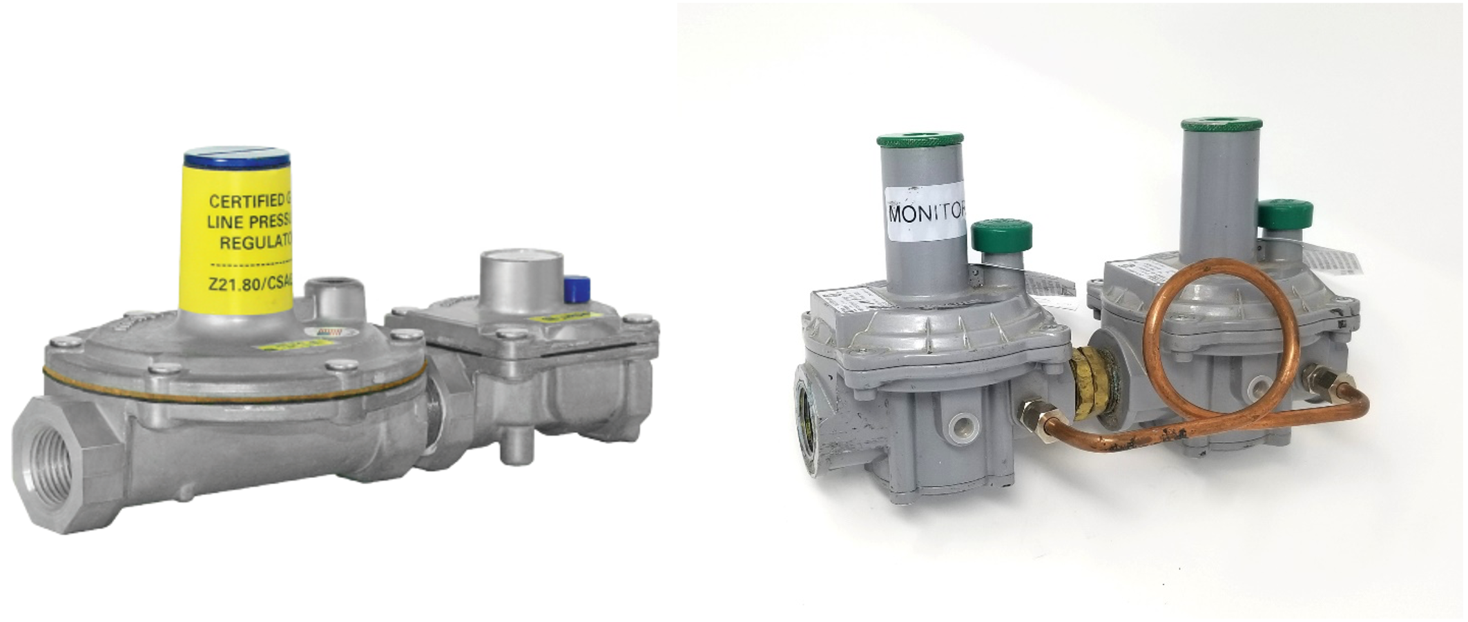
The image on the left in Figure 13 is a series regulation system also known as a two stage or two cut system. In this setup the first (upstream) regulator maintains an inlet pressure to the second regulator that is within the maximum allowable operating pressure of the downstream system. If either regulator should fail, the resulting downstream pressure maintained by the other regulator would not exceed the safe maximum allowable pressure for the downstream system.
The image on the right in figure 13 is a monitoring regulator setup. The only difference in configuration between series regulation and monitors is that in monitor installations, both regulators sense the furthest downstream pressure. Thus, the upstream regulator must have a sensing control line. The monitor regulator setpoint is slightly higher than the worker regulator therefore it will only start regulating if the worker regulator fails.
Depending upon the regulator setpoints monitor regulator systems may be referred to as either:
- Upstream wide-open monitor
- Downstream wide-open monitor
Overpressure shut-off (OPSO) device
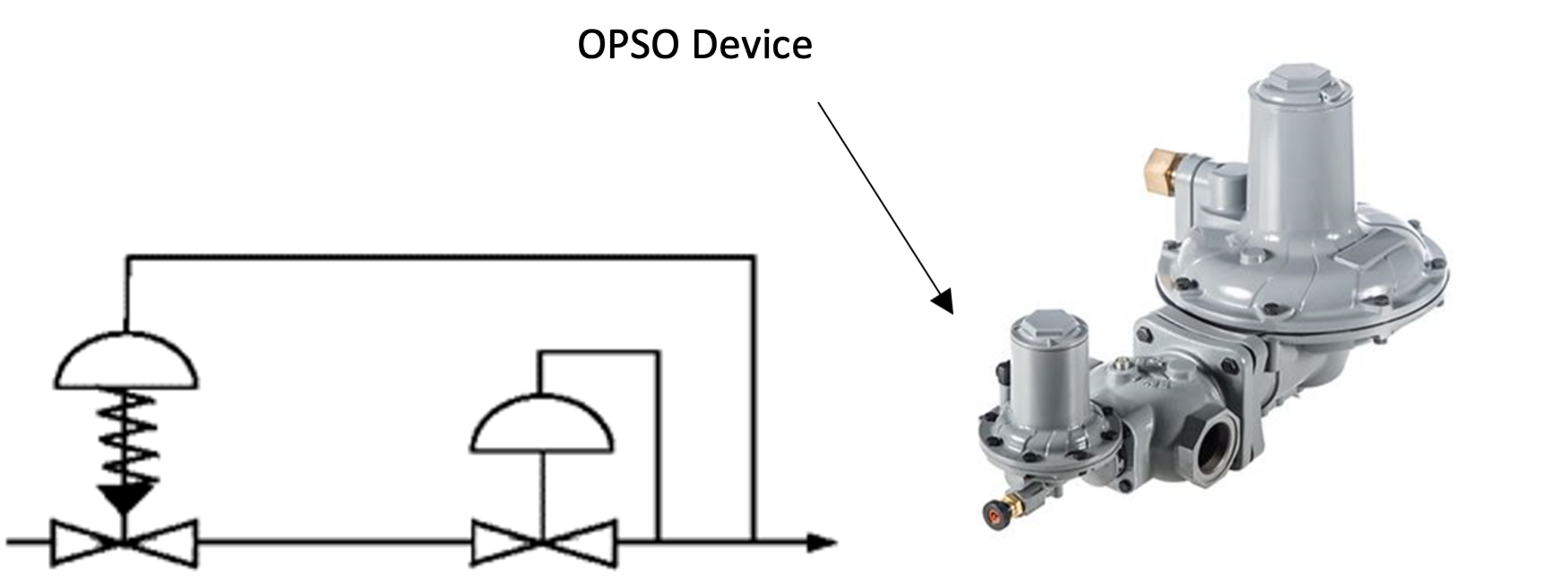
The shutoff device also accomplishes overpressure protection by containment. If an overpressure condition exists, the gas is shut off completely until the cause of the malfunction is fixed and the device is manually reset. The schematic in figure 14 indicates a spring loaded shutoff device sensing the pressure downstream of the regulator.
Vent limiters
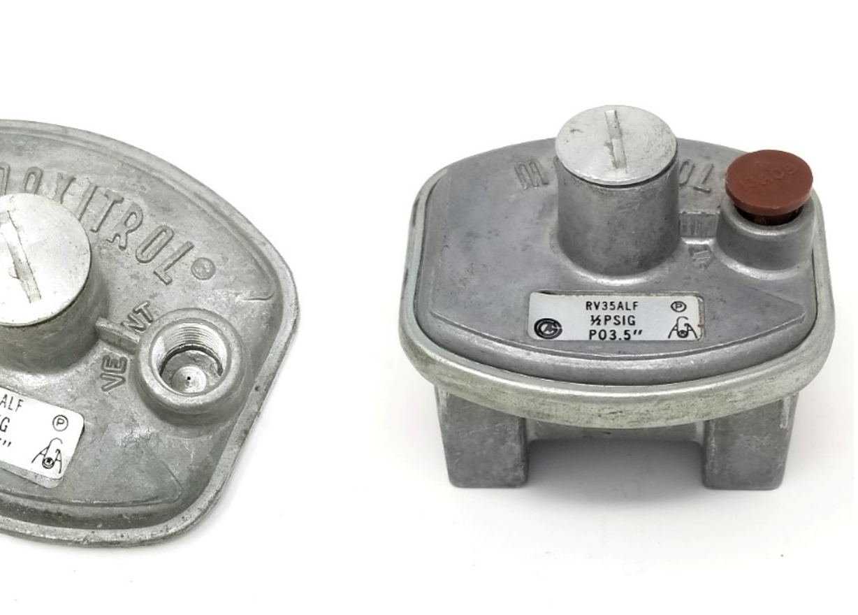
Small appliance regulators and servo regulator on combination gas valves will have a bleed vent opening with an internal orifice, usually about a #78 drill size (Figure 15 left). This opening is large enough to enable the regulator diaphragm to breath adequately but small enough to limit the amount of gas that would escape in the event of a diaphragm rupture. The threaded connection under the cap can be used to pipe the vent to away if the regulator is installed in a non-ventilated space. The vent opening is usually covered by a loose-fitting cap to prevent dirt from entering the opening (Figure 15 right).
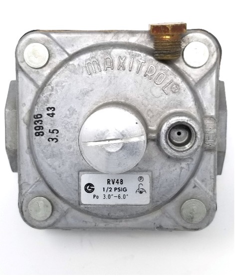
Larger regulators will have a larger bleed vent orifice to accommodate the greater amount of air that must move in and out through the bleed vent. This larger orifice will not adequately limit the escape of gas in the event of a diaphragm rupture. Therefore, when these regulators are installed indoors they must either be vented to outdoors or have some type of vent leak limiter installed. Figure 16 shows a fixed vent limiting orifice accessory sitting on the regulator, notice the regulators larger internal orifice size. The vent limiting orifice has a very small orifice opening that will restrict the air flow which will delay the regulators reaction time. To accommodate this slower reaction time the manufacture will reduce the maximum rated individual appliance capacity the regulator when using this accessory. If this regulator was required to respond at its full capacity for any single appliance then the vent limiting orifice could not be used and the vent would need to terminate outside or use an automatic vent leak limiting device.
Automatic leak limiting devices
Special leak limiting devices are designed to ensure fast diaphragm response by allowing the free movement of air under normal regulator operating conditions. However, if the diaphragm ruptures, the high pressure flow of gas causes the ball check or disc check to limit the flow of gas (Figure 17). The leak limiting device must be in the vertical position or the ball check could roll into the closed/limiting position causing the regulator to not operate properly.
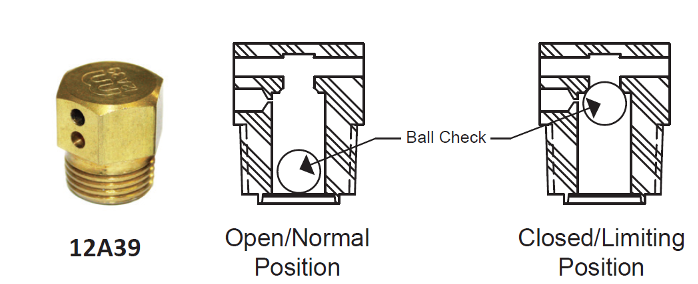
Vent leak limiting devices should not be used outdoors, if they are exposed to the environment they may become clogged by moisture or insects. Manufacturers may have more than one leak limiter available that fits the regulator, it is important that the proper model specified by the manufacturer is use.
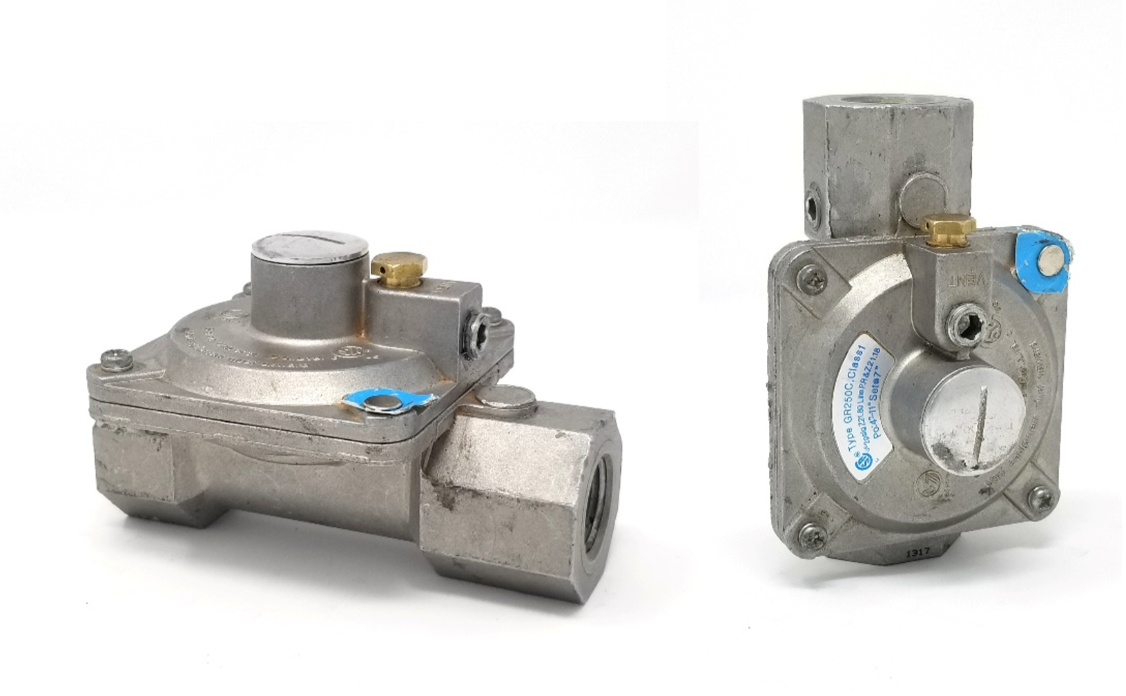
In order to keep the leak limiter vertical most manufactures will require the regulator to be mounted in the horizontal upright position. Some regulators are approved for use in the vertical position, for example Figure 18 shows a regulator designed with two vent connections which enable the regulator to be installed either vertically or horizontally using the appropriate location for the vent limiter and a plug in the other.
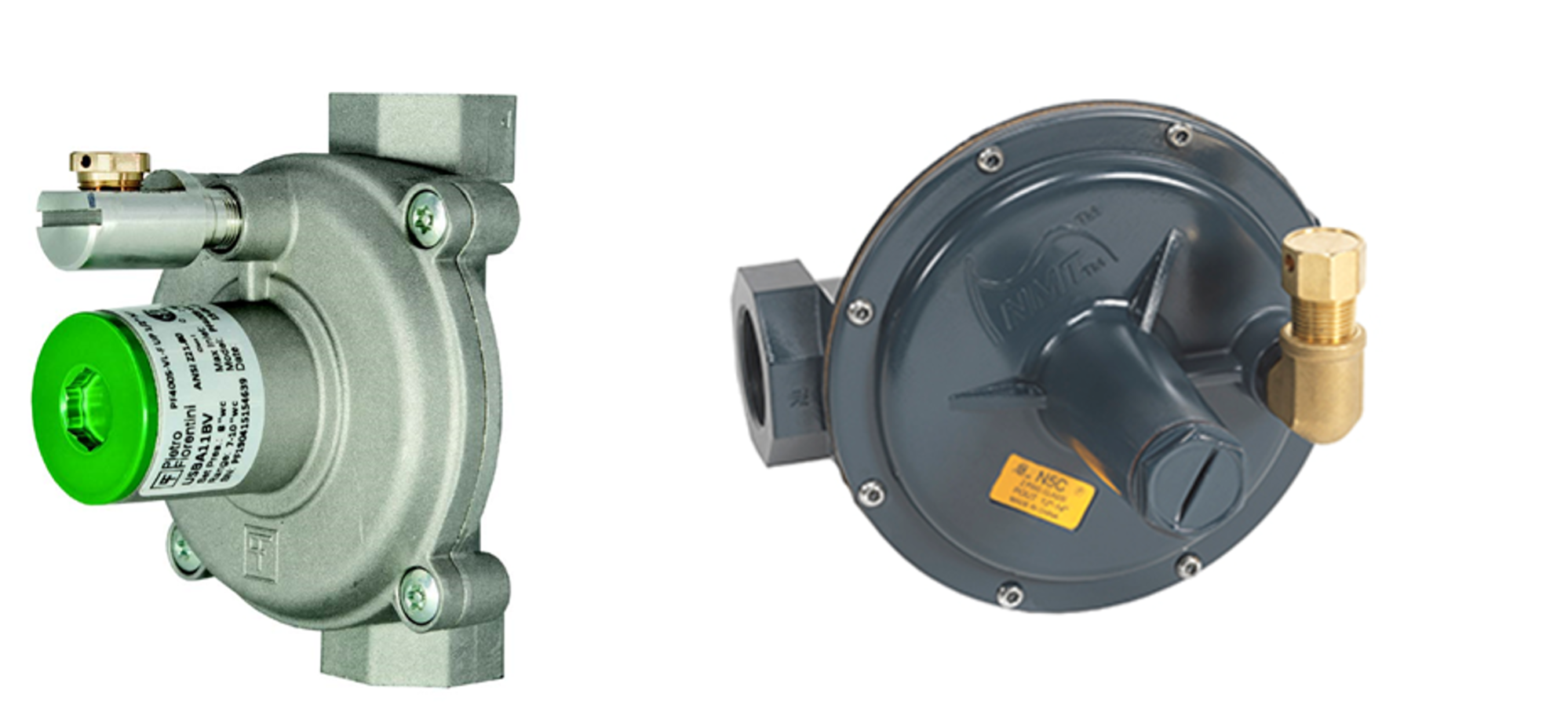
Other manufactures may have a 90 degree external vent limiter adapter available for vertical or rolled regulator orientations (Figure 19). Installers must use these manufactured certified adapters only; it is not acceptable to install you own pipe and or fittings between the regulator and the vent limiter.
General regulator installation guidelines
If installation is planned properly, the process will usually proceed smoothly.
Planning
- Verify that the regulator matches the one that was selected and ordered. Check the make, model, and pressure range.
- If you have not installed this exact regulator before be sure to read the manufacturer’s guidelines for installing the regulator.
- As part of the design and selection of the regulator a sketch of the piping system should have been created. When arriving at the site, check the sketch to ensure that the intended location of the regulator is suitable.
- Regulator location considerations include:
- place the regulator so that it can be easily serviced and there is room for a manual shut-off valve immediately upstream of the regulator and a union for future removal of the regulator.
- flow turbulence makes it difficult for the regulator to properly operate. A general rule of thumb when installing any pressure or flow sensitive control is to allow 10 pipe diameters of straight pipe on the inlet side and 5 pipe diameters on the outlet side of the control to insure laminar flow in and out of the control. Always check the regulator manufacturer’s literature, some manufactures require up to 18 inches (450 mm) of straight pipe on either side of the regulator before any change of direction or change of pipe size.
- the regulator can not be in a concealed location
- ensure that there is enough room to install a vent and sensing line if they are required.
- regulators equipped with vent leak limiting means must be installed in a ventilated space
- regulators vents must terminate outdoors, with specific clearances from other building openings, as specified in the gas code
- check gas code for additional rules regarding regulator locations
- Has the piping been pressure tested? Regulators that are not rated for the required test pressure shall not be connected to the piping system under test.
Installing
- Check the following items to ensure that the basic requirements for the piping have been met:
- Approved materials have been used for the piping.
- The piping is in an appropriate location.
- The sizing is adequate for present and future appliances.
- The piping must be properly supported so that it is aligned and does not put stress on the regulator. This could crack or warp the body of the regulator and prevent it from operating correctly or cause it to leak gas.
- If using threaded joints:
- clean the pipe threads and apply pipe lubricant sparingly to male threads, being careful to start a few threads from the end of the pipe. Loose debris or pipe sealant may become lodged in the valve/seat area of the regulator and inhibit the regulator’s ability operate.
- do not over tighten the pipe threads into the regulator, as this can damage the regulator body.
- position wrenches so that torque Is not transmitted through the regulator body
- The direction of flow through a regulator is critical for its proper operation. The flow direction will be shown by an arrow or by the words “inlet” and “outlet” at each end of the regulator. If the regulator is installed backwards it may be damaged and the diaphragm will hold the seat closed resulting in no flow.
- Regulators installed in outdoor locations will require extra protection to protect the bleed vent from the elements and debris.
- Most regulators are suitable for multi-position mounting. But if the regulator is supplied with a leak limiting device this may require that the regulator be mounted in a horizontal upright position.
- When venting is required, remove the cover from the bleed vent and use a nipple and a union at the connection, then connect the vent pipe, being careful to locate the outlet in a safe place, in accordance to all local codes, standards, and requirements.
Venting regulators
Section 5.5 of the CSA B149.1 pertains to venting of regulators. It specifies what material can be used for the vent, the size of single and combined vents, and permissible locations for vent terminations. Some of the code rules are summarized here but these should be compared to the actual language in the code. Compliance with the regulator manufacturer`s instructions is also required.
For dedicated bleed vent lines serving a single regulator, the size of the vent must be at least equal to the nominal pipe size of the vent outlet of the pressure regulator, but its inside diameter must not be less than 0.25 inches (6 mm). Not withstanding manufactures instructions if the vent line is longer than 15 m (50 ft) and it is serving a line pressure regulator or a relief valve it must be increased by one pipe size diameter for every (15 m) 50 ft or part thereof that the vent line extends beyond the initial (15 m) 50 ft. This increase must be made at the regulator vent outlet, which should include a union at the connection to the regulator.
Individual vent lines may be combined to a single (common) vent line, but the size of the common vent depends on the types of devices that are common vented. For the common vent serving regulators without internal relief the common vent must be sized to have an area of not less than twice the total area of the connected bleed vents. For a common vent serving regulators with internal relief the common vent must have an area equal to the largest relief opening plus 50% of the total area of the other relief valve openings.
Regulator vent terminations
The gas code also defines how and where the vent terminates outdoors. The vent must terminate outdoors pointing downwards and be equipped with a means to prevent the entry of water, insects, or foreign material.
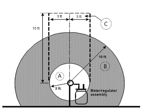
When determining where to terminate the vent to outdoors there are many clearance requirements that must be considered, such as building openings or exhaust vents. Figure 20 summarizes the clearance requirements as listed in the gas code for natural gas regulator vents. The diagram displays these requirements as they would relate to the vent outlet of a service regulator but these same clearances would apply to the outside termination of a vent from an inside the building regulator.
- For the area shown as letter A, clearance of 3 ft (1 m) is required to:
- Electrical outlet, electric meter, open flame barbeque, or other source of potential ignition
- Building openings, including all windows and doors
- Passive atmospheric air intake
- Appliance exhaust vent from a non-gas appliance or a gas dryer
- For the area shown as letter B, clearance of 10 ft (3 m) is required to:
- Mechanical (fan assisted) air intakes
- For the area shown as letter C, no gas appliance exhaust vents may be terminated.
For vents serving propane regulators the clearances to passive air intakes and ignition sources is increase from 3 ft (1 m) to 10 ft (3 m).
There are also clearance reduction allowances listed in the gas code for regulator vents that have a restricted amount of gas that could be expelled.
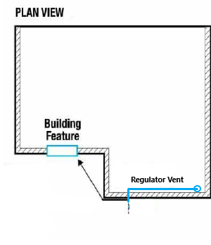
The minimum clearance must be maintained regardless if the feature is located around an outside corner. In these cases, measure as if using a string pulled tight from the outlet to the feature (Figure 21).
System start-up
Whenever introducing or restoring the gas supply to the pressure regulator, open the manual valve very slowly in the line supplying the pressure regulator. Soap test any connections that were not include in the piping system pressure test.
The regulators operation must be checked to ensure it is:
- Receiving the proper design inlet pressure at static and operating conditions
- Delivering the setpoint outlet pressure at static and operating conditions
- Maintain the maximum outlet lock-up pressure without any creepage at static conditions
Before starting the appliances check the regulator inlet and outlet static pressures. After perform the appliance start-up procedures cycle the appliance on and off multiple times to check the operating pressure setpoints and the lock-up pressure. For modulating appliances, be sure to cycle from high fire to low fire while observing operating pressures.
 Now complete Self-Test 2 and check your answers.
Self-Test 2
Self-Test 2
Media Attributions
- Figure 9. “Pop-type relief valve”.
- “Pop type relief valve” (Left) from Carremm Controls is used for educational purposes under the basis of fair dealing.
- “Fisher™ H120 Series Relief Valves” (Right) from Fisher and Emerson is used for educational purposes under the basis of fair dealing.
- Figure 10. “Direct operated relief valve” from Fisher and Emerson is used for educational purposes under the basis of fair dealing.
- Figure 11. “Direct operated regulator with internal relief” from Emerson is used for educational purposes under the basis of fair dealing.
- Figure 12. “Pilot operated relief valve” from Fisher and Emerson is used for educational purposes under the basis of fair dealing.
- Figure 13. “Line pressure regulators”.
- “GAS PRESSURE REGULATOR” (Left) from Maxitrol is used for educational purposes under the basis of fair dealing.
- “Line pressure regulator” (Right) by Camosun College is licensed under a CC BY-NC-SA licence.
- Figure 14. “Overpressure shut-off” from Emerson is used for educational purposes under the basis of fair dealing.
- Figure 15. “Bleed vent openings” by Camosun College is licensed under a CC BY-NC-SA licence.
- Figure 16. “Bleed vent with an external vent limiting orifice” by Camosun College is licensed under a CC BY-NC-SA licence.
- Figure 17. “Leak limiter” from Maxitrol is used and adapted for educational purposes under the basis of fair dealing.
- Figure 18. “Multi position 2 psi line pressure regulator” by Camosun College is licensed under a CC BY-NC-SA licence.
- Figure 19. “External vent limiter adapters”.
- “GOVERNOR & PF400” (Left) from Pietro Fiorentini is used for educational purposes under the basis of fair dealing.
- “Line and Service Regulators” from Norgas Controls is used for educational purposes under the basis of fair dealing.
- Figure 20. “Natural gas regulator vent clearances” by Camosun College is licensed under a CC BY-NC-SA licence.
- Figure 21. “String line measuring” by Camosun College is licensed under a CC BY-NC-SA licence.

