Competency C1: Install Rural Water Supply Systems
Learning Task 3
Describe the Installation of Piping and Equipment for Pressure Systems
In the Province of BC the Water Sustainability Act requires that all well drillers and well pump installers be certified and registered. An individual becomes certified as a Well Pump Installer by completing the ITA challenge process. You may also work as an unregistered well pump installer under the direct supervision of a registered well pump installer, or a professional with a competency in hydrogeology or geotechnical engineering. In many rural areas relying on private water systems, it is common for a plumbing contractor, with a certified installer, to handle the entire process of pump selection, and installation in addition to the buildings water supply piping.
The installation procedures described below pertain to a typical shallow well jet pump or a submersible pump in a well. However, the fundamental steps and considerations are applicable to various pump types, and will aid in the planning and execution of any installation.
Evaluate the Well
To ensure that the well will produce clean, clear water, the well must be developed or proven. Newly drilled wells will contain sand, mud, or debris and should have already undergone thorough development and testing by the well driller. It is advisable to verify the status of the well with the driller to ensure its suitability.
In cases were the well's condition is unknown, it is recommended to install a temporary pump to assess the water supply. The pump is activated, and the well is pumped to evaluate water quality. If the water appears turbid (cloudy), the pump continues to be run until the water clears, after which the temporary pump is removed. Subsequently, the homeowner's pump and pipe can be installed for supplying water to the residence. In situations where an existing pump is in place but the well has been unused, that pump can be utilized to evaluate the well's condition. It is essential to analyze the well water to determine its composition, as this information can influence pump selection. For instance, if the well water is highly acidic, a corrosion-resistant pump must be chosen.
Assess Well Dimensions and Capacity
Before purchasing a pump, it is crucial to calculate the estimated capacity of the well and the household's water supply requirements. It is important to note that the well log provides only an estimate of the well's capacity. Consider the time of year when the well was established, as water levels in some areas fluctuate significantly with the seasons. This will help gauge whether the estimate is relatively high or low. Wells with low yield will require a different type of pump or a distinct pumping system configuration compared to those with high yield.
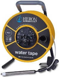
Determining the well's depth and the pumping level of water is crucial for planning the arrangement of piping and fittings and deciding where to suspend the intake piping or the pump itself. To determine the correct setting depth use the driller’s records. The well depth can be checked by lowering a weighted fishing line into the well until it touches the bottom. A fishing real with a depth counter makes it easier to measure the line length. The same setup, with a weighted float can be used to measure the water level. There are also specialized well measuring devices for company’s who are measuring wells on a regular basis. These water level meters feature a metal probe attached to a measuring tape (Figure 53). They put out a small electrical current, to a weighted probe attached to the end of a long flexible measuring tape. When the probe is submerged, the unit emits a loud beep and the static water level can be read on the measuring tape. The probe can then also be dropped until it hits the bottom to measure total well depth.
The pump inlet screen or foot valve can be placed at different levels in the water. A general rule is that they should be at least 1 m (3') below the pumping level of the water in the well. For jet pumps the foot valve or ejector should be at least 0.6 m (2’) from the bottom to prevent mud or silt from being drawn in. For submersible installations check manufacturers recommendations for the minimum setting distance from the bottom or a well. These vary from 1.5m (5’) to 3 m (10’).
The greater distance from the bottom is important for submersible pumps as their motors rely on carrying heat away from the motor by forced convection. The pumped water must flow past the motor on its way into the pump intake. It is important to set the pump above the casing perforations or well screen to ensure that fresh water from the aquifer must flow up past the pump motor rather than cascade down and into the inlet screen.
The inside diameter of the well plays a crucial role in submersible pump selection, as the pump must fit snugly within the well casing. The well cannot be too large for the submersible pump, as their electric motors require a minimum cooling flow water velocity to circulate over and around the entire motor length, to preventing overheating. (Figure 54).
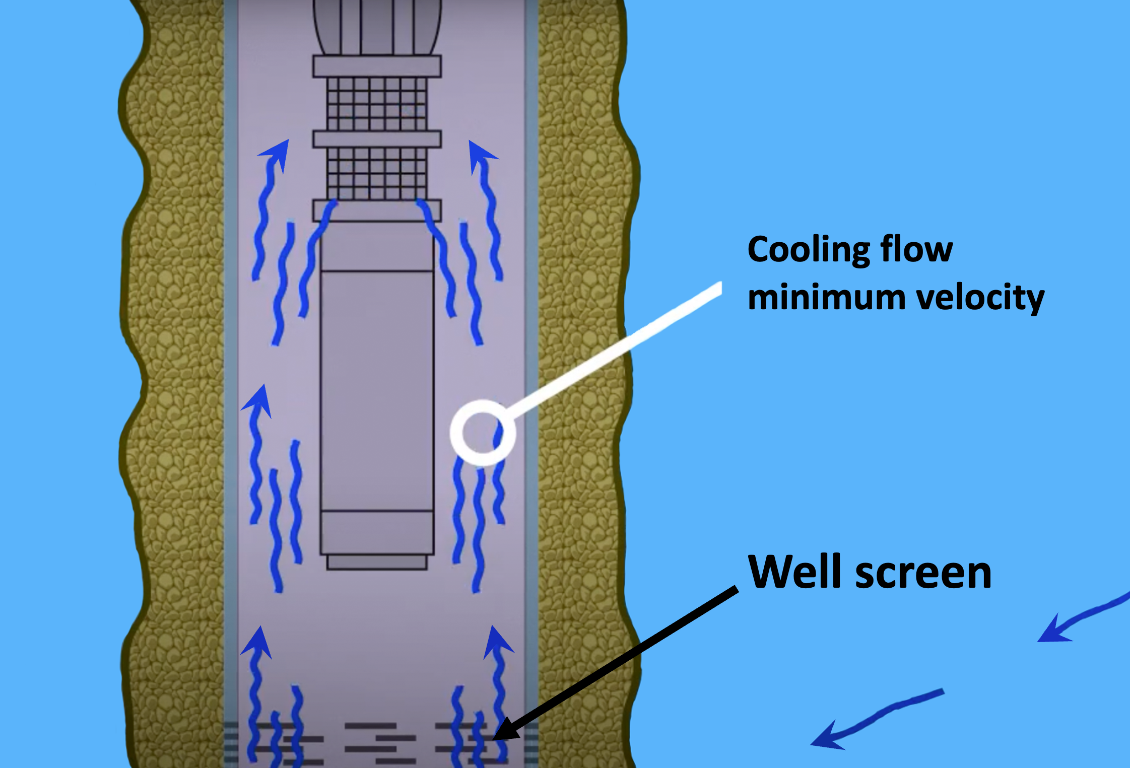
The actual flow velocity will vary based on the; well diameter, motor size and pumping capacity (gpm). Check with the manufacture to determine required cooling flow for different pump sizes. Manufacture may supply a cooling flow table by motor type and casing size. Alternately the following formula can be used to calculate the flow velocity past the motor:
[latex]fps = \frac{\text{gpm} \times 0.409}{\text{ID}^2 - \text{OD}^2}[/latex]
fps= feet per second
gpm= gallons per minute
ID= internal diameter of casing (inches)
OD = outside diameter of the motor (inches)
.409 is a constant used because of the various units of measurement used (inches, feet, etc.)
Installation Preparation
Upon receiving the pump and its components from the supplier or manufacturer, carefully inspect them to ensure there is no damage resulting from shipment. Handle the pump and fittings with caution, avoiding any dropping or impact that could cause harm. Verify that all the necessary parts are included in the package. Keep the pump in its packaging until you are ready to install it at the well.
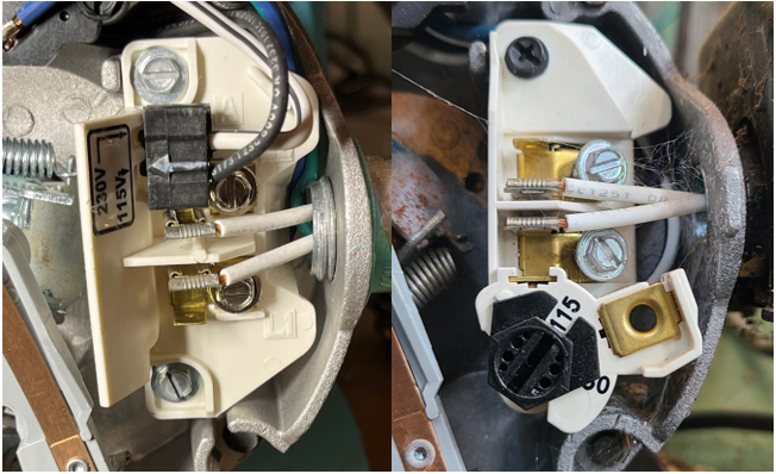
Locate a small metal nameplate attached to the motor or wired to the pump. Verify motor nameplate data meets the application – hp, voltage, phase, and Hertz. For dual voltage jet pumps check the factory setting matches your requirement. The change plug or dial is located under the motor end cover (Figure 55).
Check that the motor shaft rotates freely by hand on the second of two complete rotations. Submersible pump manufactures will supply a data plate sticker this should be attached to the well head or control box for future reference.
To minimize friction loss, it is generally recommended to position the pump in close proximity to the well. Depending on the situation, the pump may be located in a basement or a separate pump house. Ensure that the pump is placed on a level and sturdy foundation, protected from harsh weather conditions. If the pump is installed inside a building, ensure adequate ventilation is provided. Confirm that all necessary parts are available and gather any additional tools required for the installation of each component. If the well is not equipped with a well house it is advisable to use a pitless adapter and a sanitary well cap.
If the distance between the pump and the nearest electrical panel exceeds 90 meters (300 feet), a 230V circuit is recommended due to electrical losses that occur over long wire distances. Additionally, a 230V motor operates more efficiently than a 115V motor due to reduced current flow. Ensure that your power to the pump is on a circuit that is protected by a circuit breaker. A disconnect switch should also be wired in, near the pump or control box.
Ensure that the screen on the end of the suction pipe or submersible pump is suitable for the well water conditions. If the well contains sand or fine gravel at the bottom, ensure that the screen is fine enough to prevent these particles from entering the pumping system. Refer to the manufacturer's catalogues for recommendations on appropriate screen types for different soil conditions.
Flow Sleeve
For submersible installations if it was determined that the minimum cooling flow could not be met then a flow inducer sleeve (cooling shroud) must be installed onto the pump prior to installation (Figure 56). A flow inducer sleeve is also always required in an open body of water.
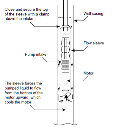
The conditions requiring a flow sleeve are:
- Well diameter is too large to achieve minimum cooling flow velocity
- Pump is in an open body of water.
- Pump is in a rock well or below the well casing.
- Pump is set in or below casing screens or perforations creating a top feeding (a,k,a, cascading) supply.
In addition to factory-made, ready-to-use flow sleeves, it is also possible to make flow sleeves from PVC pipe and stainless steel hose clamps. Both options are effective in cooling a submersible motor when sized properly. The motor sleeve is generally of the next nominal diameter of standard pipe larger than the motor or the pump, depending on the sleeve configuration used. The tubular/pipe material can be plastic or thin walled stainless steel (corrosion resistant materials preferred). The cap/top must accommodate the power cable without damage and provide a snug fit, so that only a very small amount of water can be pulled through the top of the sleeve. The fit should not be completely water tight as ventilation is often required to allow escape of any air or gas that might accumulate. The sleeve body should be stabilized by self tapping stainless steel screws installed through the side wall of the flow sleeve to prevent rotation and keep the motor centered within the sleeve. The sleeve should extend to a length of 1-2 times the sleeve diameter beyond the bottom of the motor when possible. Sleeves are typically attached immediately above the pump intake or at the pump/column connection. Avoid setting bottom of flow sleeve near bottom of well.
Pitless Adapter Installation
The general purpose of a pitless adapter is to provide a water tight, 90° connection through the well casing, below the frost line. They also provide a quick connect assembly, between the drop pipe (riser pipe) from the submersible pump or foot vales to the underground service pipe.
The slide type pitless adapters are the most common for residential and commercial applications up to 2" drop pipe sizes (Figure 57). The slide pitless adapter allows for easy installation or removal of the drop pipe by lifting the pitless elbow using a threaded pull pipe also known as a snare pipe. A single O-ring makes a compression seal between the two mating parts ensuring a leak free connection.
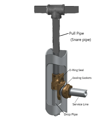
The pitless adapter will need to be installed through a hole drilled in the well casing prior to the installation of the drop pipe. A water tight sanitary seal is made using compression gaskets on both the inside and the outside of the well casing. The curved rubber compression sealing gaskets are designed to fit a range of casing sizes.
A holesaw is used to cut through the casing below ground deeper than maximum local expected frost depth. The size of the hole is determined by measuring the adapter or using the supplied template. Position the hole so the service line will be pointing the correct direction. Placing a small hacksaw cut into the upper lip of the casing and directly over the pitless adapter's outlet will help you line up the inner portion of the pitless unit once the service line is backfilled and you can no longer see the outside mating portion of the adapter. Ensure that the sealing surface on the casing is clean and smooth to allow the sealing gaskets to compress evenly as the clamping device is tightened on the outside. To install the adapter, remove the large outer nut, collar and outer gasket from the inner components. Cut and thread a pull (snare) pipe of adequate length and attach one end to the dead end threaded tapping on the top of the adapter. It is good practice to use a pull pipe that is long enough to rise above the well a comfortable height for holding and connect the top end of the pull pipe to the branch of a threaded tee with two long nipples on the run outlets of the tee to serve handles and also as a safety precaution to stop the pitless adapter and pull pipe from falling into the well. Lower the pitless adapter into the well casing to the depth of the hole and slide it through the casing. A rigid pull pipe is better for maneuvering and aligning the adapter. Make sure both the inner and outer gaskets are in place and tighten the collar and nut onto the threaded portion of the adapter that is extending through the well casing. Finally lift the pull pipe with the attached inner portion of the pitless adapter fitting out of the well to allow the inner fitting of the adapter to be attached to the pump drop pipe.
After the adapter is installed and the water service line can be connected to the adapter, be sure to keep the top of the well covered while the immediate area around the well is backfilled. Ensure that backfill does not damage your water line by carefully backfilling the area around the adapter by hand and compressing the dirt along the service line with your feet before filling the trench.
Install Submersible Pumps
The following steps outline the procedure used to install a common type of submersible pump. They are intended to introduce you to the process of installing a pump and are not applicable to all pumps. Always refer to specific manufacturer’s directions when installing pumps.
Materials
The typical materials you will need include:
- torque arrestors,
- pipe for pump drop and supply line to the pressure tank. Series #160 Polyethylene is commonly used for residential installations,
- a pitless adapter for the size of the casing and drop pipe used,
- suitable stainless steel or brass insert adapters and threaded fittings,
- clamps for connecting the poly tube to insert adapter (the clamps are to be all stainless steel, including the tightening drive nut),
- safety rope or cable used to raise the pump when servicing or replacement is necessary,
- a well cap or sanitary seal for the well,
- a pressure tank,
- a tank tee,
- a pressure switch and gauge,
- a drain valve for the tank tee,
- an adjustable pressure relief valve for system pressure protection,
- a suitable shut-off valve for the pressure tank, to be placed at the outlet of the tank tee to allow shut-off of the distribution system,
- Submersible, single phase, 3-wire motors require the use of a control box. The control box and 3-wire motor must match in HP and voltage to operate properly,
- If there is a potential for the well to run dry another electrical no-load control box is recommended to protect the pump,
- Constant pressure systems will require a special electronic control or VFD and a pressure transducer,
- screws to fasten the pump's control box to a wall,
- some electrical box wire connectors,
- a suitable water proof splice kit to attach the cable wires to the motor leads of the submersible motor,
- tie wraps to fasten the electrical cable to the drop pipe,
- appropriate size and length of electrical drop cable.
- Power cables must be selected to match the type of motor (i.e., single-phase, three-phase), voltage, horsepower and length. Always check manufacturer’s recommendations. The Table below shows a sample of the range of wire sizes that are specified for each type of submersible motor depending upon the total cable length required from the motor to the service power panel.
- If the control box will be located close to the well head, as in a dedicated pumphouse, then the pump portion of the cable length should be cut long enough to reach the control box. In cases were the control box will be located away from the well head, within the building, then the pump portion of the total cable should be long enough to reach to the top of the well head with enough slack to make a connection to the wires coming from the control box in the building. The motor leads may be smaller than the specified cable, this is acceptable as the motor leads are short and there is virtually no voltage drop across the leads.

Table notes:
- Both jacketed cable and single conductor cables may be used other then values marked Bold and * indicating conductor only (not jacketed).
- Table based on copper wire. If aluminum wire is used, multiply lengths by 0.5. Maximum allowable length of aluminum is considerably shorter than copper wire of same size.
Submersible Pump Installation Steps
- After carrying out the general pre-installation checks, assemble the pump and motor if necessary.
- Never use a wrench on any part of the pump except the machined flats on the top of the pump.
- Splice the motor cable. The splice requires covering with a shrink tube containing a sealing compound that releases when the shrink tube is heated, forming a seal for the electrical splice. The wires should be trimmed back to place each individual splice in the wires a short distance apart from the next splice to avoid a large ball of excess material at the splice location. A general procedure for splicing cables with a heat shrink splice kit is:
- check that motor cable and drop cable are in good condition
- stagger the motor leads by cutting each one successively shorter
- cut the drop cable leads to match
- if installing a single-phase motor, match colours
- strip about 13 mm (½”) of insulation from each lead
- slide pre-cut heat shrink tubing onto leads
- connect leads with connectors and crimp the connecting lugs
- slide tubing over connections and heat until tube contracts and sealant flows
- spliced should be tested with an ohmmeter for leaks to ground prior to pump installation. Procedure for testing motor cables and splices are explained in Learning Task 5.
- Lay out the riser pipe sections, fittings and pump. Make sure you have the appropriate thread compound, fittings or cements to join steel or plastic piping. Compare your measured well depths with the length of piping to ensure that the submersible will be suspended at the correct depth. The pump should always be at least 0.9 m (3’) below the maximum drawdown level of the well. If you use plastic piping, remember to allow for the stretching that will occur.
Some people will cut a length of 4² PVC pipe and attach it to the bottom of pump motor to act as a support to keep the pump a pre-set distance from the bottom of the well. This practice is not recommended as it will affect the cooling of the motor and potentially void the manufactures warranty. - Connect the first section of riser pipe to the discharge outlet of the pump. Make sure that you do not overtighten the threaded connections as this could damage the check valve in the discharge chamber and destroy the pump. Extra long barbed insert adapters are available for hanging pump on poly riser pipe. When tightening the threaded adapter into the pump only grip the pump by the two flats at the top of the pump. Do not hold the pump housing during installation of the riser pipe adapter or a check valve.
If the pump uses an external check valve it will need to be installed first into the top pf the pump. - All polyethylene pipe connections should be double-clamped. The clamps should be installed in an alternate arrangement to place one head of a clamp on either side of the tube and the clamps should be placed to clamp over the barbs of the adapter. Do not overtighten the clamps, as they can be stripped. When applying the clamps, keep them as close together as possible, and tighten them in steps, snugging them up many times rather than tightening them in one step. Remember that the polyethylene you are using will be quite stiff and will slip more easily onto the mating portion of the barbed fitting if the poly is warm. In colder conditions, it may be necessary to warm the pipe ends with warm water or carefully with a heat gun. Do not heat the tube with a torch, as overheating may change the plastic to a brittle compound that can break under the stress of service.
- Install a torque arrestor (Figure 58 left) to keep pump centered and control flexing movement of the pipe caused by the pump starting and stopping. The first torque arrestor is typically installed 18"-24" above the submersible pump. Installation practices can vary depending on the depth, type of pipe and the pump horsepower. Some installers will install additional arrestors at 75-100 ft intervals to prevent the piping from rubbing the side of the casing and wearing the pipe and or cable. Cable guards (Figure 58 right) are another option to keep the upper section of the drop pipe centered and keep the power cable from rubbing against the well casing.
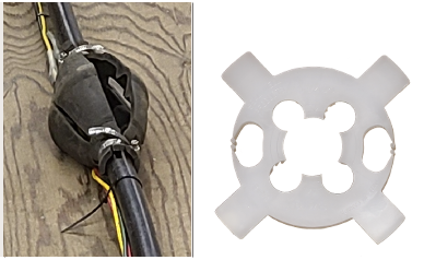
Figure 58. Torque arrestor and cable guard - Use cable ties to secure the drop cable to the riser pipe at minimum of 3m (10 ft) intervals to prevent cables tangling or being damaged. When securing the cable to the riser pipe, allow 2 inches of slack between the intervals as plastic pipe tends to stretch under load. Avoid using electrical tape to fasten the wires, as it is known to loosen and detach in the moist conditions of the well, commonly ending up at the intake of the pump and blocking it.
- Attach a safety rope to the pump to assist in removal of the pump from the well. Under no circumstances should the pump be removed by using the electrical wires to lift the pump and discharge piping. Most pumps will have an integral hook or loop in the top of the pump to attach the rope securely.
- Lower the pump and first section of riser pipe into the well. Depending on the type of drop pipe there are a number of different methods that are used to lower the pump smoothly and prevent damage.
- If using polyethylene make sure to remove any sharp edges on the casing. Some installers will make a protective donut or rollers to help guide the pipe over the casing edge. Getting the full length of pipe, pump and wires into the well is heavy work that requires two people in charge of feeding the pipe down into the well head, and a third guiding the top end of the pipe.
- If steel or ridged plastic pipe is used then some type of overhead hoist will be needed that is tall enough to elevate a full length of pipe. You will also need riser clamp or pipe holder to span the top of the well head for temporarily supporting the lowered sections each time you join the next section of pipe.
- Slowly lower the pump, piping, power cable and safety rope to the required depth, clipping the drop cable and adding any necessary additional torque arrestors or cable guards. For pump settings 60 m (200 ft) or deeper, manufacturers recommend the installation of additional spring-loaded in-line check valves at regular 60 m (200 ft) intervals.
An ohmmeter, or megger should be used to measure the insulation resistance on the power cable every 20 feet as the pump is lowered. This will locate any fault in the cable.
Procedures for testing the insulation resistance are explained in Learning Task 5 - Depending on whether the drop pipe will exist the well below or above ground, terminate the drop pipe with either a well seal or a well cap with pitless adapter (Figure 59).
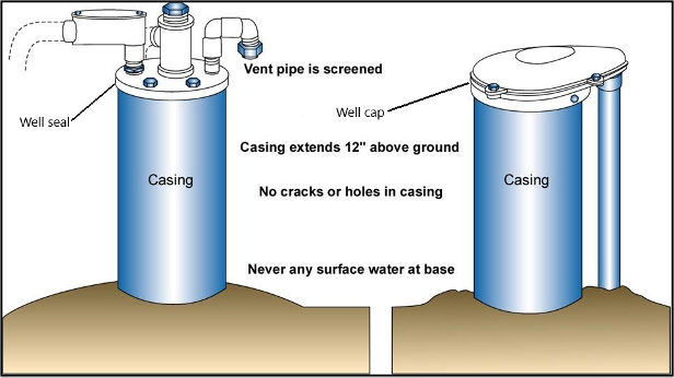
Figure 59. Well seal and well cap terminations - For an above ground well seal termination, connect the necessary pipe adapter and threaded nipple onto the end of the drop pipe, while supporting the installed string of drop pipe. Slip the seal down over the threaded nipple and connect an elbow or tee for the above ground fitting. Run the pump cable and safety rope through threaded electrical conduit hole. Lower the pipe string until the tee or elbow is down on the seal, and the seal is seated on the well casing. Tighten the bolts to squeeze the packer against the inside of the well casing and the pipe. The other ½” threaded connection can be used to connect a well vent if needed.
- For a pitless adapter with well cap termination, slowly lower the drop pipe straight down the well with the snare pipe in your hands (Figure 60). As it lowers, with a small movement of the snare pipe feel the opening you are looking for. You may have to lift and turn the snare pipe slightly before it aligns and drops into the other half of the pitless unit. The adapter will seat with a solid feel when the two sections are properly meshed. Tie the end of the safety rope onto the rope hanger plate.
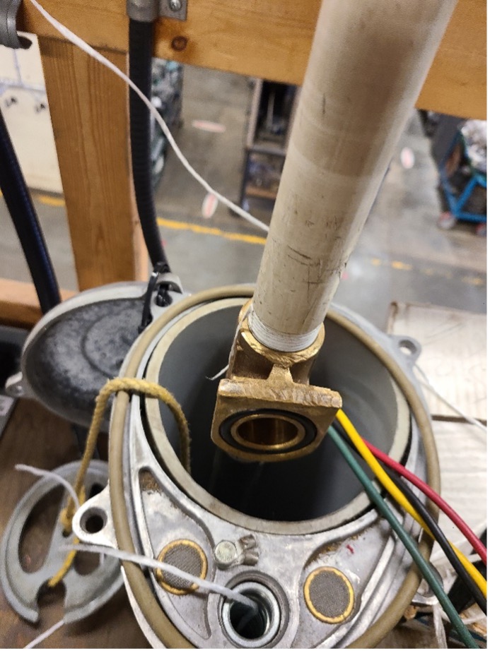
Figure 60. Well cap and pitless being installed 
- All pump wiring must be protected from physical damage. Submersible pumps usually have their power supply placed in the ditch with the water supply line to the residence. Armoured cable (Teck) or electrical conduit are laid from the house to the well at a depth of 3' (1 m). A 3' (1 m) depth of bury allows for some protection from shallow digging operations such as for gardens. The conduit/Teck cable comes up beside the well casing and is connected to the well cap for secure fastening. The conduit/Teck is commonly tie-wrapped to the casing below ground level to keep it vertical while backfill is placed. The wires going to the pump and the wires coming from the house are commonly fastened together with watertight connections at the top of the well. The metal well head and metal casing must be connected to the ground circuit. Excess wire is left neatly coiled in the top portion of the well casing under the well cap to allow electrical measurements to be made at the well head.
- Connected the pump power cable to the pump panel, control box, VFD or constant pressure controller as per manufactures instructions (Figure 61). Always connect the control box or panel-grounding terminal to supply ground per the Canadian Electrical Code (CEC) requirements.
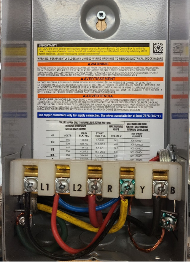
Figure 61. Control box connections - Connect the power supply and connections between the pressure switch and the control box as per the manufactures instructions and Canadian Electrical code (CEC). Include a disconnect switch near the control box.
After electrical work is completed and before pump is connected to pressure tank, the pump should run to test the water for clarity.
Pump start up will be covered in Learning Task 4- Describe the testing and commissioning of water supply pressure systems.
Install Jet Pumps
The following steps outline the procedure used to install a common type of convertible jet pump. They are intended to introduce you to the process of installing a shallow well or deep well jet pump and do not apply to all pumps. Always refer to specific manufacturer’s directions when installing pumps in the field. The diagrams and instructions refer to PVC piping material but other approved material could be used.
In a deep well installation, the jet assembly is submerged in the well because the vertical distance to the water level exceeds the maximum practical suction lift of 25 ft. Adjustment of the regulator causes the correct amount of water to be diverted back down to the jet for the most efficient operation. The regulator may also be used to restrict the flow of water in a shallow well system if the convertible pump has the capacity to draw more water than the well can produce. In a shallow well installation, the jet assembly is attached directly to the pump because a vacuum will adequately lift water to the pump.
Shallow Well Installation
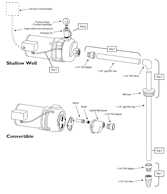
Before beginning the installation be sure to complete the installation preparation checks. Some pump assembly may be required. For example, you might need to connect the ejector onto the pump body for a convertible style of jet pump. Make sure that the pump foundation is firm and level. Secure the pump to the foundation. If the pump is near or in the house, place a rubber mat or under cushion between the pump and foundation to help deaden pump noise. Locate the pump as close to the well as possible to minimize friction losses. Refer to Figure 62 for these typical shallow well installation instructions.
- Connect foot valve to 1-1/4” plastic pipe adapter and cement adapter to 1-1/4” rigid PVC pipe.
- Add rigid PVC pipe sections and couplings (as required) while lowering foot valve into well to the proper depth. The foot valve should be at least 0.9 m (3’) below the pumping level and at least 0.6 m (2’) from the bottom. Verify these minimum dimensions with the manufacture.
- Install well seal over rigid PVC pipe and into well casing. Cement 1-1/4” PVC elbow to top of pipe at correct length to position foot valve at proper depth. Lower foot valve/piping assembly carefully into well, using pipe riser clamp to hold onto. Draw up bolts on well seal until rubber gaskets are tight against both the well casing and the pipe.
- Continue connecting horizontal piping from the well head to the pump, you may want to install unions when connecting to the pump. This pipe should slope upwards to the pump to avoid air locks. If the horizontal piping run from the well to the pump is more than 12 m (40’), some manufactures recommend the installation of a check valve near the pump.
- Connect pressure tube between pump case and pressure switch on pump.
- Install discharge tee in pump discharge until tight.
- Make the electrical connections to the pressure switch as per the manufactures instructions and Canadian Electrical code (CEC). Include a disconnect switch near the pump.
- After electrical work is completed and before pump is connected to pressure tank, the pump should be primed and test run.
Priming and start up will be covered in Learning Task 4 - Describe the testing and commissioning of water supply pressure systems
Deep Well Installation
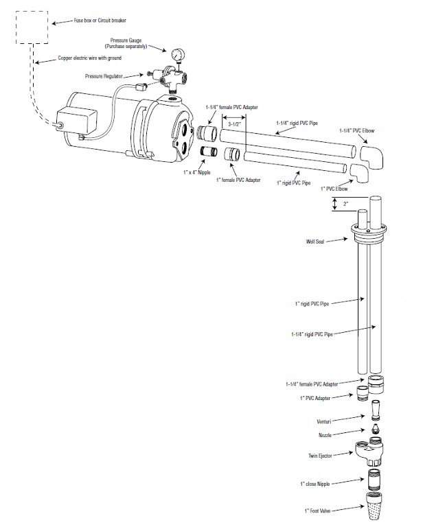
Before beginning the installation be sure to complete the installation preparation checks. Refer to Figure 63 for these typical shallow well installation instructions.
- Begin installation by attaching foot valve to close nipple of corresponding size. Connect nipple/foot valve assembly to bottom of ejector body. Next install plastic nozzle and venturi into top of ejector body.
- Use adapters to connect a section of pressure and suction piping to the ejector body. Pressure piping is usually 1” diameter and suction pipe is 1¼” in diameter.
- Add rigid PVC pipe sections and couplings (as required) while lowering the ejector assembly into well to the proper depth. The ejector should be at least 0.9 m (3’) below the pumping level and at least 0.6 m (2’) from the bottom. Verify these minimum dimensions with the manufacture.
- After lowering pipes and ejector assembly into well, install well seal. Draw up bolts on well seal until the rubber gaskets are tight against the well casing and the two plastic pipes. For deep well jet pump, fill the vertical pipes with clean water before connecting to horizontal piping. This will help in priming the pump.
- Cut top of 1” pipe 2” shorter than the 1-1/4” pipe, as shown in the installation diagram. Cement 1-1/4” PVC elbow and 1” PVC elbow to the top of each pipe.
- Connect horizontal piping from the well head to the pump. These pipes should slope upwards to the pump to avoid air locks.
- Make the electrical connections to the pressure switch as per the manufactures instructions and Canadian Electrical code (CEC). Include a disconnect switch near the pump.
- After electrical work is completed and before pump is connected to pressure tank, the pump should be primed and test run.
Priming and start up will be covered in Learning Task 4- Describe the testing and commissioning of water supply pressure systems.
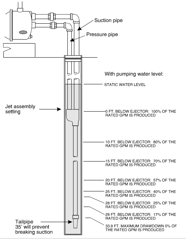
If you are installing a deep well pump in a weak well, you may connect the foot valve and screen onto an 11 m (35’) tailpipe which is coupled to the ejector assembly. As the water lowers past the ejector fitting the suction head will increase, reducing the capacity of the pump. The farther the water lowers below the fitting, the lower the amount of water the pump can produce, until the delivery capacity of the pump matches itself with the amount of water coming into the well from the aquifer.
Install Pressure Tanks
Although the well would have been developed and proved by the driller prior to the pump installation, it is good practice to test the well water for clarity before connecting to the pressure tank and house piping.
Priming and start up are covered in Learning Task 4- Describe the testing and commissioning of water supply pressure systems
For these instructions it is assumed you are installing a diaphragm or bladder type pressure tank, were pressure tank has previously been selected and sized to match the requirements of the pumping system..
Upon receiving the tank from the supplier or manufacturer, carefully inspect it to ensure there is no damage resulting from shipment. Keep the tank in its packaging box until you are ready to install it. Check the factory pre-charge of air in the tank with an ordinary tire gauge onto the valve stem at the top of the tank. If there is no factory precharge this may be an indication of a faulty tank. You may need to add of remove compressed air so that the pre-charge is correct for your system. The pre-charge pressure is only to be measured or adjusted when there is no water in the pressure tank. For conventional fixed speed pump systems, the precharge pressure should be approximately 2 psi lower that the cut-in setting of the pressure switch. For example, if the pump has a 30/50 PSI switch, the tank pre-charge pressure should be 28 PSI.
For pressure tanks serving a constant pressure pumping system the precharge pressure is usually about 70% of the actual controller setpoint, but check with the manufacture instructions.
Determine the best location for the pressure tank, for jet pumps the tank should be located as close as possible to the pump. Never install the tank where it could freeze. A floor drain located in close proximately will help with service and maintenance of the system. Place tank in a vertical position on a level surface. The base should be fully supported to ensure maximum stability and the floor should be stable and level. Some small inline tanks do not have a base, these will need to be suspended and supported independently of the piping, with the tank connection on the bottom. Locating the connection on the bottom for water supply pressure tanks ensures that any sediment that might accumulate in the tank is flushed out with each pumping cycle.
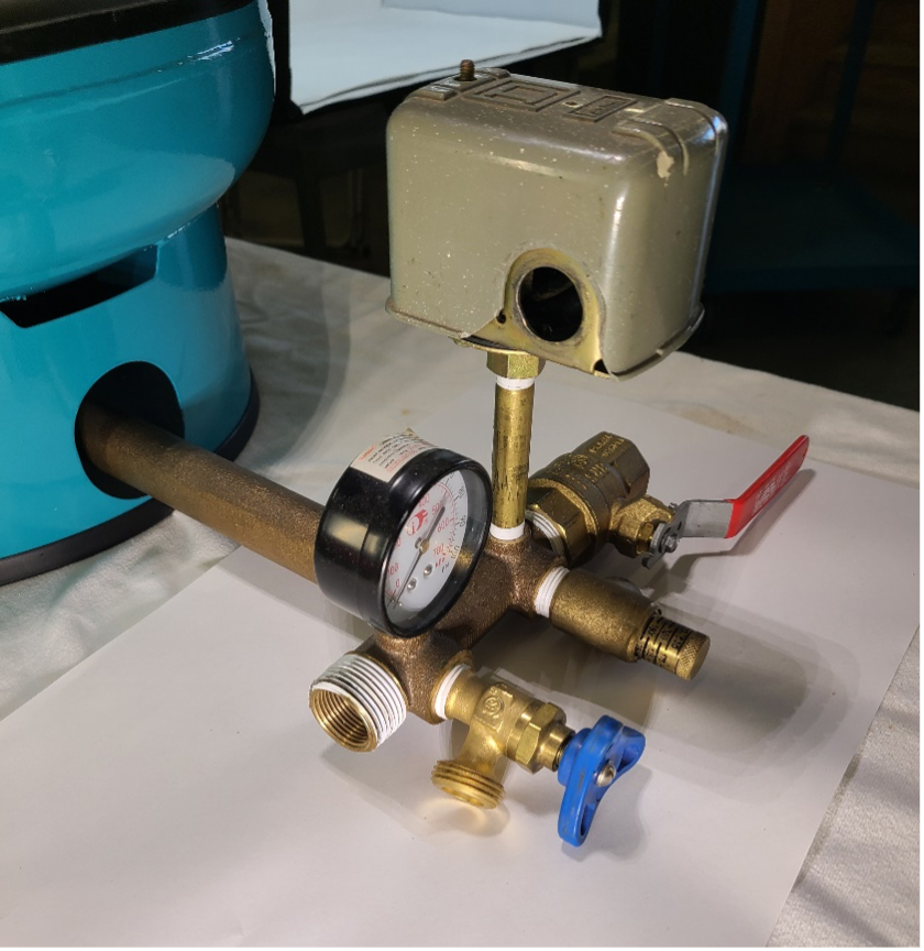
After the pump has been test run and the water is clear connect the pipe and fittings to the tank. The system should include at least one union for service, tank tee, gauge, check valve, pressure relief valve, drain valve, pressure switch or (VFD pressure sensor), and a valve to isolate the service line from the pressure tank. By using an appropriate length tank tee you can easily incorporating all of these components into the system at one convenient location (Figure 65).
Pressure Switch Wiring
As has been previously mentioned you should not attempt any electrical wiring procedures unless you are qualified and know exactly what you are doing and how to proceed with it. Even the most casual treatment of electricity can kill you and cause severe damage to property, equipment and other personnel.
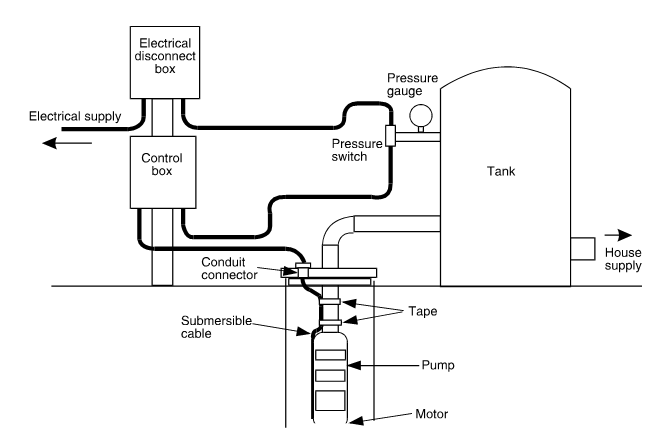
Surface wiring connections for pumps can vary depending on the type of pump used and the demands of each installation. Jet pumps are supplied with the pressure switch attached to the pump body and the wiring from switch to the motor already completed. For submersible pumps a common configuration of control box, disconnect box, motor and pressure switch connections is shown in Figure 66.
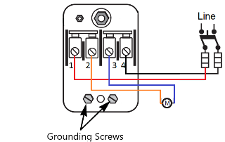
The pressure switch is a double pole single throw switch (Figure 67). First connect the ground wire to one of the grounding connections. The incoming power leads are connected to the two outer screws (1 & 4). The inner screws (2 & 3) are responsible for linking to the motor supply in the case of a two-wire submersible pump, or connecting to the L1 and L2 terminals in the control box for a three-wire pump.
 Now complete Self-Test 3 and check your answers.
Self-Test 3
Self-Test 3
Media Attributions
- Figure 53. "Water level meter" from Heron Instruments Inc. is used for educational purposes under the basis of fair dealing.
- Figure 54. "Submersible motor cooling" from video from Grundfos is used and adapted for educational purposes under the basis of fair dealing.
- Figure 55. "Dual voltage change plug (left) or switch (right)" by Rod Lidstone is licensed under a CC BY-NC-SA licence.
- Figure 56. "Flow inducer sleeve [PDF]" from Grundfos is used for educational purposes under the basis of fair dealing.
- Figure 57. "Slide pitless adapter" from Near North Supply is used for educational purposes under the basis of fair dealing.
- Figure 58. "Torque arrestor and cable guard"
- Torque arrestor (Left): by Rod Lidstone is licensed under a CC BY-NC-SA licence.
- Cable Guards (Right): by Boshart is used for educational purposes under the basis of fair dealing.
- Figure 59. "Well seal and well cap terminations" from the United States Environmental Protection Agency is used for non-commercial, scientific and educational purposes.
- Figure 60. "Well cap and pitless being installed" by Rod Lidstone is licensed under a CC BY-NC-SA licence.
- Figure 61. "Control box connections" by Rod Lidstone is licensed under a CC BY-NC-SA licence.
- Figure 62. "Shallow well pump installation" from Pentair Myers is used and adapted for educational purposes under the basis of fair dealing.
- Figure 63. "Deep well pump installation" from Pentair Myers is used and adapted for educational purposes under the basis of fair dealing.
- Figure 64. "Low yield well tail pipe solution" from Grundfos is used for educational purposes under the basis of fair dealing.
- Figure 65. "Connected tank tee" by Rod Lidstone is licensed under a CC BY-NC-SA licence.
- Figure 66. "Submersible pump wiring" by Camosun College is licensed under a CC BY-NC-SA licence.
- Figure 67. "Pressure switch wiring" by Camosun College is licensed under a CC BY-NC-SA licence.
Image Descriptions
Table: 60 Hz 75°C (167°F) Maximum Submersible Power Cable Length Max. Cable Length In Feet (Meters) - Service Entrance to Motor [Skip Table]
| Motor Rating (Volts) | Motor Rating (H.P.) | Size: 14 | Size: 12 | Size: 10 | Size: 8 | Size: 6 | Size: 4 | Size: 3 | Size: 2 | Size: 1 | Size: 0 | Size: 00 | Size: 000 | Size: 0000 |
|---|---|---|---|---|---|---|---|---|---|---|---|---|---|---|
| 115 | ½ | 100 (300) | 160 (49) | 250 (76) | 390 (119) | 620 (189) | 960 (293) | 1190 (363) | 1460 (445) | 1780 (543) | 2160 (658) | 2630 (802) | 3140 (957) | 3770 (1149) |
| 230 | ½ | 400 (122) | 650 (198) | 1020 (311) | 1610 (491) | 2510 (765) | 3880 (1183) | 4810 (1466) | 5880 (1792) | 7170 (2185) | 8720 (2658) | 10620 (3237) | 12660 (3859) | 15210 (4636) |
| 230 | ¾ | 300 (91) | 480 (146) | 760 (232) | 1200 (366) | 1870 (570) | 2890 (881) | 3580 (1091) | 4370 (1332) | 5330 (1625) | 6470 (1972) | 7870 (2399) | 9380 (2859) | 11250 (3429) |
| 230 | 1 | 250 (76) | 400 (122) | 630 (192) | 990 (302) | 1540 (469) | 2380 (725) | 2960 (902) | 3610 (1100) | 4410 (1344) | 5360 (1634) | 6520 (1987) | 7780 (2371) | 9350 (2850) |
| 230 | 1 ½ | 190 (58) | 310 (94) | 480 (146) | 770 (235) | 1200 (366) | 1870 (570) | 2320 (707) | 2850 (869) | 3500 (1067) | 4280 (1305) | 5240 (1597) | 6300 (1920) | 7620 (2323) |
| 230 | 2 | 150 (46) | 250 (76) | 390 (119) | 620 (189) | 970 (296) | 1530 (466) | 1910 (582) | 2360 (719) | 2930 (893) | 3620 (1103) | 4480 (1366) | 5470 (1667) | 6700 (2042) |
| 230 | 3 | 120* (37) | 190 (58) | 300 (91) | 470 (143) | 750 (229) | 1190 (363) | 1490 (454) | 1850 (564) | 2320 (707) | 2890 (881) | 3610 (1100) | 4470 (1362) | 5550 (1692) |
| 230 | 5 | Blank | 110* (34*) | 180 (55) | 280 (85) | 450 (137) | 710 (216) | 890 (271) | 1110 (338) | 1390 (424) | 1740 (530) | 2170 (661) | 2680 (817) | 3330 (1015) |
| 230 | 7 ½ | Blank | Blank | 120* (37*) | 200 (61) | 310 (94) | 490 (149) | 610 (186) | 750 (229) | 930 (283) | 1140 (347) | 1410 (430) | 1720 (524) | 2100 (640) |
| 230 | 10 | Blank | Blank | Blank | 160* (49*) | 250 (76) | 390 (119) | 490 (149) | 600 (183) | 750 (229) | 930 (283) | 1160 (354) | 1430 (436) | 1760 (536) |
| 230 | 15 | Blank | Blank | Blank | Blank | 170* (52*) | 270 (82) | 340 (104) | 430 (131) | 530 (162) | 660 (201) | 820 (250) | 1020 (311) | 1260 (384) |

