Competency C2: Install Residential Water Treatment Systems
Learning Task 3
Describe the Installation of Water Treatment Equipment
Learning Objectives
After completing the learning tasks in this chapter, you will be able to:
- Identify considerations involved in water treatment equipment installations, and
- describe the appropriate installation procedures for various types of water treatment equipment
The installation of water treatment equipment must always follow manufacturers’ specifications and recommendations. To not do so may jeopardize warranties and may also be ineffective in providing the intended corrections to water quality. Also, the following points must be considered when water treatment and equipment is required.
Safety
Safety is always paramount in any workplace. Workers must follow provincial and federal directives, such as those of WorkSafe BC, on any jobsite. If access to a confined space is necessary, the appropriate confined space entry procedures must be followed to the letter. Certified eye protection and safety footwear are standard Personal Protective Equipment (PPE) in any workplace scenario, with the possibility of hard hats, high visibility outerwear, and any other PPE to suit the specific installation site. Appropriate gloves should be used if there is a possibility of contact with rough surfaces or harmful chemicals, and the guidelines found in WHMIS legislation are always expected to be followed whenever working with hazardous products. A site assessment for safety should always be completed prior to any installation of equipment.
Transport and Handling
Equipment such as tanks can be heavy and awkward to handle and may require two people to ensure personal safety and to protect the equipment from damage. Two-wheeled hand trucks and dollies are usually beneficial tools when moving tanks and heavier components into place.
Items such as softeners and tank-type filters may be supplied pre-loaded with various layers of media, such as coarse gravel, fine gravel, and zeolite. It is extremely important that these tanks be transported as vertically as possible, to prevent the media layers from mixing, which can reduce the effectiveness of the device. The interior vertical space of many service vans is not high enough to allow the tanks to be loaded upright, so alternate arrangements for transport may be necessary.
Tools and Equipment
Most water treatment equipment is installed using standard tools found in a plumber’s toolbox. Square-jawed wrenches such as spanners and adjustable wrenches are best for flat nuts as they won’t mar the surfaces. Pipe wrenches should only be used on pipes where the jaw marks left won’t be an issue, otherwise a strap wrench should be considered for any exposed piping. Teflon tape or pipe dope is appropriate for use on threads, provided any dope used is compatible with potable water and Teflon tape is applied leaving the first two threads bare, to avoid it balling up and being carried downstream. If installation involves soldered connections, avoid unnecessary heating of any fittings close to O-rings, washers, or plastic pieces. If they can’t be isolated or dismantled, make sure to apply a wet rag as a heat sink between the heat and the vulnerable piece. Steel or galvanized pipe and fittings should not be used, due to corrosion issues. Also, the installation should conform to the requirements of the governing plumbing code.
Site Considerations
The need for water treatment is more a rural than an urban probability. Most treatment items will require a power supply and a protected area that is heated and has an adequately sized drain. Consequently, structures such as a pumphouse situated at the wellhead may be a good choice for locating whole house equipment provided an electrical supply and adequate room for equipment was considered at the planning stage. A backup electrical power supply should also be a consideration, at minimum to power the well pump but, more importantly, for protection from freezing during power outages. Otherwise, the equipment is best located adjacent to the water service entry point within the building. Placing equipment in a room without a solid floor should be avoided. Manufacturers usually specify installation on a firm, dry, stable base. Contact with moist soil or gravel may have an adverse effect on the bottoms of any tank or vessel. As well, the height and small footprint of filters and softeners make them prone to toppling, so they should be strapped to the structure using seismic-resistant components. The room should be adequately lit, heated, and ventilated.
Space Considerations
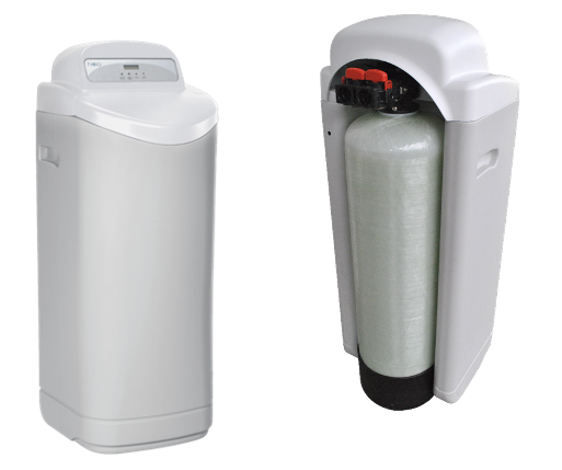
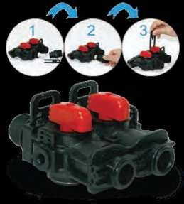
Most whole house water treatment equipment is floor mounted and will often require a fair bit of space for service and maintenance. This is rarely considered at the construction stage, so the norm is for equipment to be crammed into tight spaces. Items such as softeners and manganese greensand filters require a filter media tank and a second tank for the regeneration solution, which can be problematic for space needs. However, while manganese greensand filters are not normally supplied as single units, water softeners can be. Combination softener/brine tanks are available where the filter is located within the brine tank, or the brine tank wraps around the filter, as seen in the image below. These cabinet-type units need less floor space for their installation and in many cases may be the best option.
Cross Connection Control
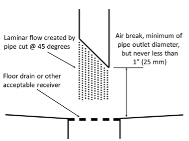
Any connections to a drainage system, from any water treatment device, must be made through an air break. This means there must be an unobstructed vertical space between the bottom end of the outlet pipe and the flood level rim of the drain, never to be less than 1 inch (25 mm) in height. This is a requirement of water purveyors and plumbing codes, and any contravention could have dire consequences. Filters or equipment that have the capability to automatically regenerate, such as softeners, will have an outlet that must be piped in a way that provides an air break while preventing splashing and overflow during operation. Cutting the end of the drain line at a 45-degree angle and securing it so it can’t be knocked out of position usually achieves this result.
Sequence of Equipment
Depending on the source of supply and intended uses of the water, treatment units have a recommended sequence for installation. In the following figures, there are allowances for both raw water to outdoors and for hard filtered water usage. Some system outlets, such as for livestock feeders and exterior hosebibbs on a well system, have little need for treated water, and their inclusion in the treatment system will essentially be a wasteful practice. However, certain hosebibbs would benefit from dispensing softened water, such as those routinely used to supply water for car washing. Hard water deposits on the vehicle finish, called “spotting”, are unsightly and extremely difficult to remove. The “specialty” hosebibb should be adequately marked as such to prevent unnecessary use of softened water.
The drains and valves in the figures that follow have been omitted for clarity. It is important, when installing multiple water treatment devices in series, that a sampling valve be installed in the piping downstream of each device. This allows the results of testing procedures, explained in the next chapter, to be obtained more accurately.
Figure 25 below shows the installation of an activated carbon filter and water softener on a municipal supply. Most municipal supplies deliver water that is free of large debris. If required by code, the integral screen of the pressure reducing valve (not shown) will capture debris that occasionally makes it through the system to that point. The activated carbon filter will take care of smaller particles that may pass through the PRV’s screen and flush them to drain through its backwash cycle. If a pressure reducing valve isn’t needed, a good choice would be to install a whole house cartridge type filter either upstream or downstream of the meter, as local bylaws allow. The softener should be installed downstream of the carbon filter and under no circumstances should water softeners be installed downstream of a water heater. Hot water will destroy the zeolite resin in the mineral tank of a softener. As well, the softener should always be protected from backflow of hot water from the water heater. The vacuum relief valve, installed on water heaters to prevent the collapse of the tank in the event of backflow created by backsiphonage, may in some circumstances be adequate for this purpose. A better choice would be an atmospheric vacuum breaker to both prevent tank collapse and prevent backflow. Because some water treatment devices change the quality of water due to the filter material used in the treatment process, the water softener should be the last piece of water treatment equipment in a series of treatment devices.
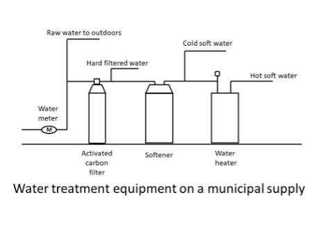
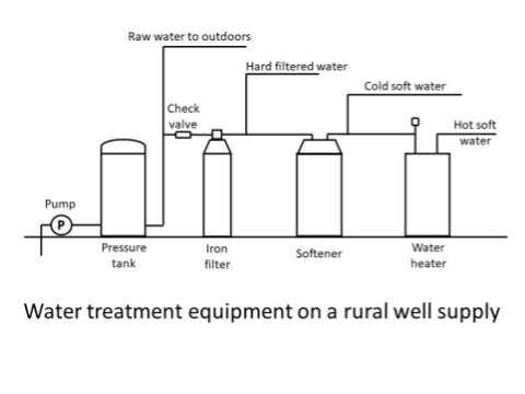
Figure 26 below shows a rural water supply system using an iron filter. When iron or sulphur in any other than minute amounts are present in the water supply, the softener’s resin bed will become clogged. A dedicated iron filter protects the integrity of the softener.
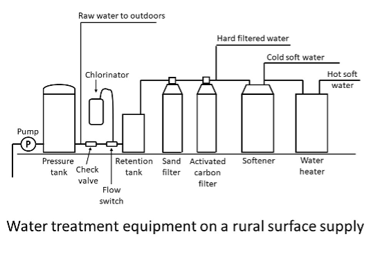
Multiple water treatment devices may be necessary when the quality of the water supply is poor. In Figure 27 below, a surface water supply source uses a chlorinator to remove bacteria and iron content. A sand filter is installed downstream of the chlorinator to reduce sediment and filter out the precipitated iron from the chlorination process. An activated carbon filter installed downstream of the sand filter will remove any taste and odour resulting from the chlorine and any hydrogen sulphide associated with the iron. The water softener, always located upstream of the water heater, takes care of hardness issues and any trace amounts of remaining iron.
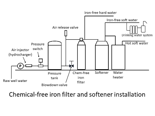
When a chemical-free iron filter is used, the standard procedure is to install an air injector, known as a hydrocharger, on the pipe feeding into the pressure tank. Some manufacturers state that the hydrocharger should be located on the upstream side of the pressure switch to prevent the pump from rapidly cycling when the hydrocharger operates. Flow rates surrounding the installation of a chemical-free filter are critical. Piping should be sized according to manufacturers’ instructions and an air release valve is necessary at any high point upstream of the filter when using a bladder-type pressure tank in conjunction with a chemical-free iron filter. Any accumulation of air on the piping feeding the filter must be avoided. As water flows through the hydrocharger, air is drawn in through a venturi and iron is oxidized, forming rust particles that can be filtered. Some of these will precipitate out of the relatively still water in the pressure tank. To remove them, the tank is periodically “blown down” such as is done with a steam boiler. The chemical-free iron filter will take care of the remainder of the iron precipitate. Again, locating the iron filter upstream of the softener protects the softener’s resin bed from becoming clogged.
Figure 28 below shows a typical well system for water that may be high in iron content.
When a chemical-free iron filter is to be installed and there is a desire to also supply raw water for outdoor use (called “split-stream”), some manufacturers recommend the installation of two pressure tanks, as shown in the following figure. The hydrocharger is installed between the primary and secondary pressure tanks, and a normally closed solenoid valve is installed upstream of the hydrocharger. A secondary pressure switch is installed, downstream of the hydrocharger, that is wired to operate the solenoid valve.
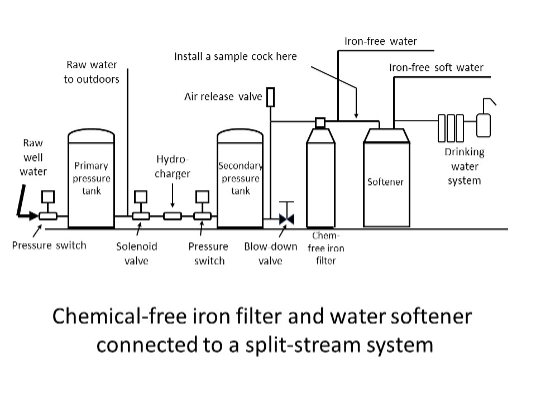
Systems using a chemical-free iron filter require precise planning and component placement, and strict adherence to manufacturers’ installation recommendations is strongly suggested.
Installation Accessories
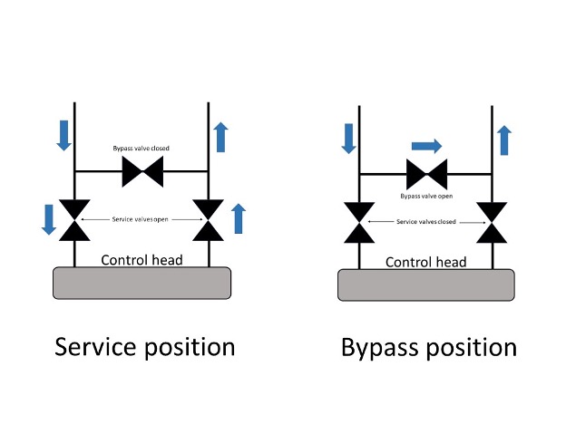
Bypass valving allows the shutdown of equipment for routine maintenance without shutting off flow to the rest of the house. Manufactured bypass valves are either a supplied component of a softener or are available as an accessory. They are constructed of brass or plastic and connect to the rear of the control head with clips and O-rings. An optional 90-degree bypass adapter is available that allows the softener to be installed closer to the wall than if using a standard bypass valve that is oriented horizontally.
Alternatively, a piped bypass can be constructed onsite using standard pipe, valves, and fittings. Figure 31 is a diagram of a common bypass arrangement in the service and bypass positions.
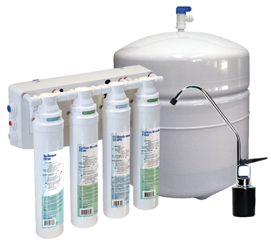
Reverse Osmosis (RO) Units
Residential RO units are considered point-of-use water treatment devices, normally mounted on the inside wall of the kitchen sink cabinet. Manufacturers use a combination of 3/8” and ¼” plastic tubing of different colours to ensure no piping crossovers occur. Water supply is taken from the cold line feeding the sink via a saddle tee/valve. This is common practice although the plumbing code states that saddle-type fittings are prohibited, and so some jurisdictions may insist that the supply be made through a fitting arrangement that conforms to code. The drain line connects to the sink’s continuous waste on the upstream side of the trap via a supplied saddle-type fitting (also normally prohibited by code). This connection is critical in that it constitutes a direct cross connection that may contaminate the water supply. However, the installation is deemed acceptable because the connection between the RO unit and drain is through an air gap built into the dispensing spigot mounted on the countertop adjacent to the sink. Older RO models may not have this feature and should not be reinstalled.
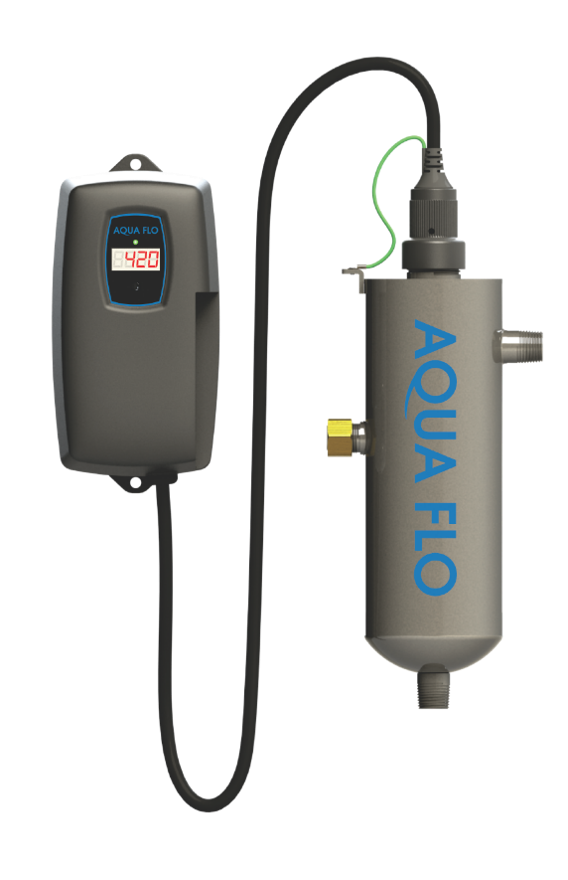
Ultraviolet (UV) Sterilizers
For UV sterilizers to be effective, they must have an uninterrupted power supply and a high-quality upstream filtration system. Firstly, without an operational electric supply to power the UV lamp, there will be no microorganisms rendered harmless. They will pass through the system and multiply. Secondly, viruses and other living organisms are so small that even the tiniest particle of dirt or grit between them and the UV bulb can block the UV rays, again allowing them to pass through the system untreated. The water entering the unit should be pre-treated to the following levels:
- Less than 7 grains per gallon of hardness, or less than 120 PPM
- Free of color and crystal clear.
- Iron should be less than 0.3 mg/L.
- Manganese should be less than 0.05 mg/L
- pH range should be 6.5 to 9.5
- 5-micron filtration
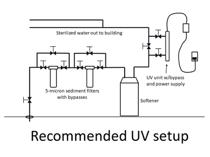
There should be two 5-micron filters, piped in series, on the incoming water supply, with bypasses around each filter to enable filter replacement without system shutdown. Also, there should be a piped bypass around the UV unit. If the bulb is being replaced, there should be no flow allowed through the system until the UV unit can be re-started. If the UV unit is out of commission while water is needed to be supplied, the system should not be used for drinking water purposes and the system should be sanitized prior to re-establishment of the UV’s operation.
The UV unit can be mounted in any orientation although horizontal is preferred and should be located where it can be routinely inspected and serviced. There should also be adequate space at its service end to allow replacement of the mercury bulb. They are normally provided with an alarm to alert the homeowner of any power interruption, so the alarm transmitter should be located where it can be heard easily. Manufacturers’ installation instructions are very specific and must be followed exactly if bacterial contamination issues are to be avoided.
 Now complete Self-Test 6 and check your answers.
Self-Test 6
Self-Test 6
Media Attributions
- Figure 23. “Novo® 485HE cabinet softener” from NOVO® is used with permission.
- Figure 24. “Air break” by Camosun College is licensed under a CC BY-NC-SA licence.
- Figure 25. “Water treatment equipment on a municipal supply” by Camosun College is licensed under a CC BY-NC-SA licence.
- Figure 26. “Water treatment equipment on a rural well supply” by Camosun College is licensed under a CC BY-NC-SA licence.
- Figure 27. “Water treatment equipment on a rural surface supply” by Camosun College is licensed under a CC BY-NC-SA licence.
- Figure 28. “Chemical-free iron filter and softener installation” by Camosun College is licensed under a CC BY-NC-SA licence.
- Figure 29. “Chemical-free iron filter and water softener connected to a split-stream system” by Camosun College is licensed under a CC BY-NC-SA licence.
- Figure 30. “Horizontally-oriented manufactured bypass” from NOVO® is used with permission.
- Figure 31. “Onsite-fabricated piped bypass arrangement” by Camosun College is licensed under a CC BY-NC-SA licence.
- Figure 32. “NOVO® reverse osmosis system” from NOVO® is used with permission.
- Figure 33. “Recommended UV setup” by Camosun College is licensed under a CC BY-NC-SA licence.
- Figure 34. “NOVO® Ultraviolet sterilizer” from NOVO® is used with permission.
