Competency C1: Install Rural Water Supply Systems
Learning Task 1
Describe Pressure Water Supply Systems
Private pressure water supply systems rely on pumps and pressure tanks to deliver water to taps and appliances throughout a building. The system typically includes a well or other water source, a pump to extract the water from the source, and a pressure tank to store the water and maintain a consistent pressure in the system. This ensures that there is a consistent flow of water at an appropriate pressure, making it a convenient and reliable source of water for daily use.
Types of Water Supply
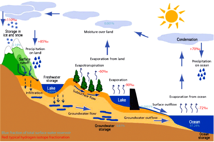
Private water supply systems can be classified based on the source of water they use. The two main types of private water supply systems (Figure 1) are surface water systems and groundwater systems .
Surface Water Systems
Surface water systems draw water from rivers, lakes, or ponds. They are often used in areas where groundwater is not available or where the surface water source is closer to the property. Surface water systems require different components and treatments than groundwater systems to ensure that the water is safe and reliable. Surface water quality can be affected by various factors, including nutrient runoff, algae blooms, sedimentation, and pollution from industrial discharge, agricultural runoff, or sewage treatment plants.
Groundwater Systems
Groundwater systems draw water from underground aquifers. An aquifer is an underground layer of permeable rock, sand, or soil that contains and transmits water (Figure 2). The water in the aquifer comes from rain and snowmelt that seeps into the ground and is stored in the spaces between soil particles or in the cracks and crevices of rock.
Aquifers can vary in size both vertically and horizontally. They can range from a few meters thick to being as vast as the Ogallala Aquifer, which is equivalent in size to California. Aquifers have different levels of porosity, which refers to the spaces found between rocks, gravel, and sand. However, the foundation of the aquifer is made up of solid rock that doesn’t allow water to pass through, known as bedrock. The porosity of the aquifer affects the rate at which water can move through it and how fast the aquifer can be replenished after water has been extracted from them.
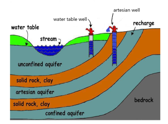
Aquifers can be classified as either confined or unconfined. An unconfined aquifer is also known as a shallow well aquifer because its water table, which is the top layer of water, is located near the surface of the ground. This type of aquifer does not have a dense layer of rock or material above it, so its water is not under pressure and can be easily affected by conditions on the surface. This means that any pollution or contamination on the surface can easily seep into the shallow well aquifer and affect the quality of the water. In contrast, a confined aquifer has a layer of dense rock or material above it which keeps the water under pressure and protects it from surface contamination.
Aquifers can be accessed through springs and wells. Although they are naturally replenished, an aquifer can be depleted by overuse or contamination.
Springs
Springs are natural sources of groundwater that flow to the surface. Springs are created when a portion of an underground aquifer reaches the surface and intersects with a stream, lake, or rock formation, resulting in the formation of a small pool due to the natural shape of the land. They are often found in hilly or mountainous areas, where the water table intersects with the surface (Figure 2). Springs are often considered reliable sources of drinking water since they originate from groundwater. However, it is important to note that springs are susceptible to contamination, similar to other surface water sources. As the water from springs flows through the upper layer of soil and collects on the surface, it can be easily influenced by various contaminants.
Artesian springs derive from aquifers where the water is pressurized, resulting in a force that propels the water to the surface. Artesian water sources are typically situated at greater depths and flow beneath a dense layer of clay or rock. When a well is drilled into the aquifer or geological forces create fractures in the clay or rock layer, water may forcefully gush or bubble up to the surface. These types of springs are less vulnerable to contamination and exhibit greater reliability compared to gravity-fed springs, especially during periods of dryness or drought.
Wells
Wells are a vertical shaft that is dug, driven, drilled, bored or jetted into the ground to access groundwater. The diameter of a well is largely dependent on the method used to install it. The length or depth of a well is dependent on where the aquifer is located and how much water is required. Shallow wells are generally thought of as anything less than 7.6 m (25′) deep. Shallow wells are relatively easy and inexpensive to install, but they are more susceptible to contamination from surface water runoff or nearby septic systems.
Choosing a suitable location for a potable water well is crucial for ensuring the availability of safe and clean drinking water. The selection process should consider the proximity to potential sources of contamination, such as septic systems, landfills, and chemical storage facilities. Geological conditions like soil type, depth to bedrock, and the presence of fractures, folds, or faults can influence the water quantity and quality. The distance from the proposed well site to nearby surface water bodies like lakes, streams, or wetlands is also important to prevent contamination from runoff or seepage. You must also consult with local authorities to comply with regulations regarding the minimum setbacks from property lines, structures, and utilities.
A qualified hydrogeologist or well driller will assess the suitability of the site and the construction design to optimize the well’s yield and protect the aquifer from potential contamination sources. In British Columbia, all wells are governed by the “Groundwater Protection Regulation.” This document covers all aspects of well operation, including well registration.
Well Construction
Well construction is a process that involves drilling, installing and constructing a well to access groundwater. Well construction is a complex process that requires careful planning, design, and construction to ensure that the well is safe, reliable, and provides high-quality water.
The Groundwater Protection Regulation (GWPR) includes a Code of Practice for Construction, Testing, Maintenance, Alteration and Closure of Wells. The Regulation outlines such things as:
- Who is qualified to drill a well and install a well pump?
- How to identify a well.
- How to protect groundwater by installing proper surface seals, how to flood proof wells, how to protect the well head, and how to deactivate and close unused wells.
- That wells are identified by tags through the provincial ID system.
- That well drillers and pump installers must be registered.
- Deactivation of unused wells to protect the aquifer from contaminants entering
- Flood proofing to prevents surface water from entering a well.
Well Types:
There are different types of wells, including:
- dug
- bored
- drilled
- driven
Dug wells
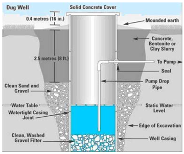
Dug wells are the simplest and oldest type of wells, and are excavated by hand or with a backhoe. They are typically shallow, only reaching depths of 10-30 feet. Dug wells are often lined with bricks, stones, or concrete to prevent collapse and contamination.
Bored wells
Bored wells are a type of well that is similar to a dug well, but instead of being excavated by hand, they are dug using a drilling machine with an auger bit. The typical largest diameter of a bored well is around 1 meter, but this can vary depending on the specific drilling equipment and the needs of the well. For example a larger diameter bore hole can help serve as a storage reservoir during periods of high demand. Bored wells are best installed in clay, silt, and fine sand, as these materials are easily excavated by the auger. They are not suitable for hard rock or soil that contains many large boulders, which can damage the auger and make it difficult to drill the well. When considering a bored well, it’s essential to evaluate the soil and rock formations in the area carefully to ensure that the well will be drilled safely and effectively.
Driven wells
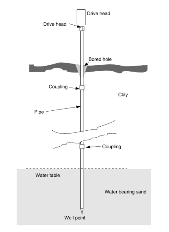
Driven wells are another type of shallow well most commonly used in areas with shallow water tables. They can be installed relatively quickly and easily by pounding sections of pipe, tipped with a special drive point-screen assembly, into the earth until the aquifer is reached. This method can be done using a hand-operated maul or a heavy weight supported by a frame that is lifted and lowered by a motor-drive assembly. The purpose of the point-screen assembly is to allow water to enter the pipe while preventing soil and debris from entering.
Drilled wells
When it comes to establishing a well, drilling a hole may be the most effective option if the soil is dense, contains clay or rocks, or if the water source is deep. Drilling a well also enables penetration of the impervious layers to access the confined aquifers. Drilled water wells usually have a diameter of 101 mm to 152 mm (4″ to 6″) and range from 30 m to 90 m (100′ to 300′) deep.
Lining a drilled well with pipe casing is an essential step in protecting the confined aquifer from contamination. The pipe casing is installed at least all the way down into the impervious layer, which acts as a barrier between the aquifer and any potential sources of contamination. Proper installation of the casing is crucial to prevent any gaps or leaks that could allow contaminants to enter the aquifer.
Well components
The well construction must comply with the provisions of the GWPR. The driller must ensure that the well is built to meet the minimum standards for the casing material, wellhead completion, surface seal, well caps and covers, and proper identification. Figure 5 depicts the crucial components of a well, however, the requirements may vary depending on the geological formation and type of well being constructed.
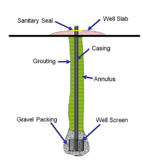
Sanitary seal
A sanitary seal is a watertight seal that prevents surface water from entering the well. It is typically installed around the top of the well casing. Technically the complete casing seal is made up of both, the above ground penetration point and the below ground grouting.
Well slab
The well slab acts as a surface seal by preventing surface water from entering the well. The slab is usually made of concrete and is placed over the top of the well casing, extending beyond the edge of the casing to form a barrier between the well and the surrounding soil. The slab is typically poured in place on a level, compacted soil surface and reinforced with steel to provide additional strength. The surface of the slab is also sloped away from the well to prevent water from pooling near the wellhead. The combination of the slab and a properly installed well cap help to prevent contamination of the well water from surface sources.
Casing
Casing is a pipe that is installed into the well to prevent the walls from collapsing and to prevent contamination. It is typically made of PVC or steel and is installed during drilling or after the well has been dug. The length of casing varies for different geological formations. For drilled wells the surface casing will be set into the bedrock to maintain the integrity of the impervious layer. Depending on the stability of the rock strata below the initial bedrock, additional production casing or a PVC liner may need to be extended down through the initial surface casing.
The casing diameter must be large enough to accommodate the size of the pump that is required. For residential installations 6” casing is most common, as this will accommodate a liner (if needed) with a 4” submersible pump. The casing must stick-up a minimum of 0.3 m above the well stab or elevated ground.
Annulus
When the initial unconsolidated ground material is being drilled a bit is used that is at least 5 cm larger in diameter than the casing that will be installed. The annulus is the space left between the well casing and the surrounding soil or rock.
Grouting
After the drilling has penetrated the bedrock a minimum of 1 m then the casing is set. Grouting is part of the casing setting process were the space between the well casing and the surrounding soil or rock is filled with a non-toxic sealant to prevent below ground surface water from entering the well. It also helps to stabilize the well casing and prevent contamination.
Type of sealant considerations include; thickness of the annular space and the depth as well as artesian pressures. Commonly used sealants include:
- Bentonite clay mixtures
- Concrete grout
- Sand, cement grout (consisting of sand, cement, and water)
Well screen
Depending on the composition of the water bearing strata a well screen may be required to prevent sediment form entering the well. A well screen is a pipe that has slots or openings that allow water to flow into the well while preventing sediment from entering. It is typically installed onto the bottom of the liner or casing and is surrounded by gravel.
Gravel packing
Gravel packing is often used to fill the annular space between the liner/casing well screen and the borehole wall to help prevent the formation of sediment and improve the flow of water into the well.
Well logs
A well log is a detailed record of the characteristics and conditions encountered during the drilling and construction of a water well. It provides information about the geology, hydrogeology, and properties of the formations encountered, including the depth and thickness of different rock layers, the presence of aquifers and aquitards, and the water-bearing capacity of the well. The details listed on a well log give the plumber a map of important well characteristics necessary to ensure that the water supply system is designed and implemented effectively and in line with the specific characteristics of the well.
Since 2005 the BC Water Sustainability Act has required well drillers to register new wells with the province. This process includes attaching a well identification plate to the well casing and submit the well records to the Ministry of Environment.
Pumps
In a private water system, the primary component responsible for water extraction is the pump. Pumps make it possible to economically lift water from a private water source and make it available where it is desired; Pumps are available in various types and sizes to suit different water sources, including deep wells, shallow wells, and surface water. Pumps can be broadly categorized into two types: positive displacement and non-positive displacement pumps.
Positive Displacement Pumps
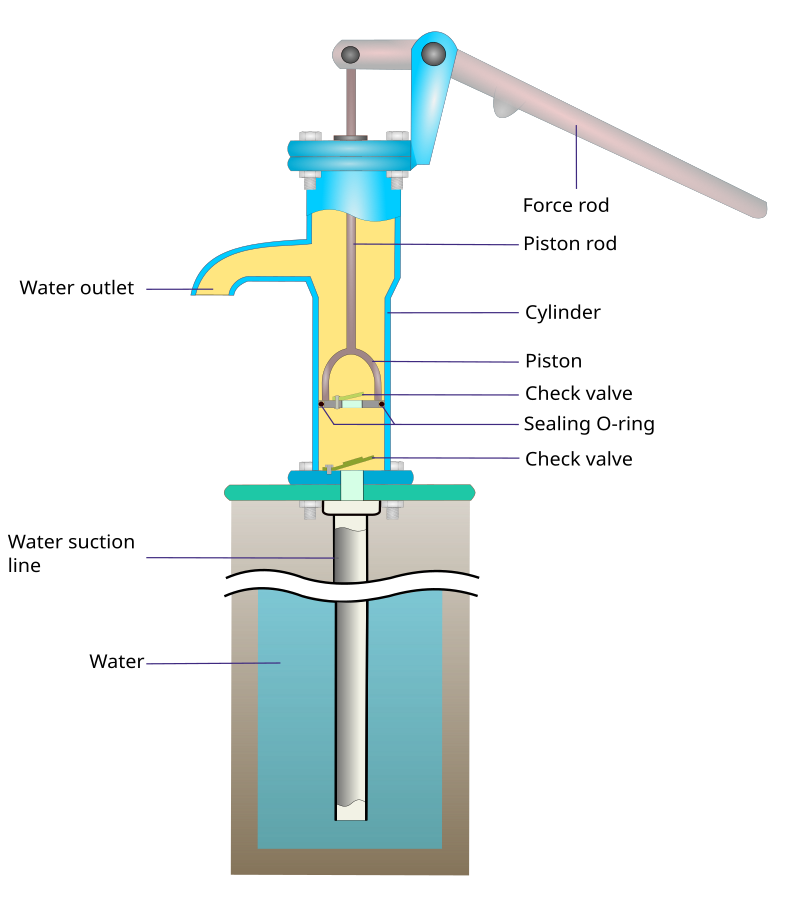
Positive displacement pumps, as the name suggests, displace a fixed volume of fluid with each cycle of operation. They work by trapping a specific amount of fluid and then forcing it through the pump’s outlet. The simple manually operated lift pump, that can still be found in parks and campgrounds, is an example of piston type of positive displacement pump, as each stroke delivers a fixed volume water (Figure 6).
The motorized versions, also known as reciprocating pumps, have a piston that moves inside a cylinder contained in a housing, equipped with check valves. The piston moves back and forth, drawing water from the suction inlet on its back stroke and forcing the water into the discharge outlet as it is pushed forward by the motor (Figure 7).
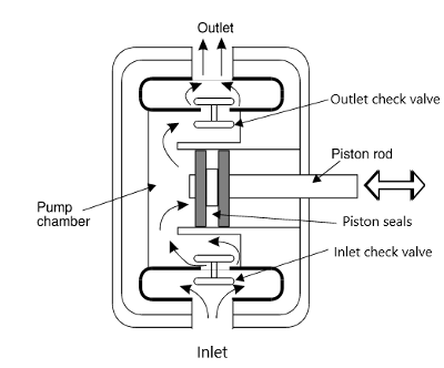
Positive displacement pumps are able to fill themselves and the suction pipe with fluid, which is called self priming. Water begins to flow from the well because the backward stroke of the piston lowers the pressure (creates a vacuum) inside the pump and allows the atmospheric pressure that bears on the well water to force the water up the suction pipe.
Although piston pumps were very reliable and tolerant of air that may leak into intake lines they are not generally used anymore for private water supply, as they are more expensive and nosier than other pumps.
Non-Positive Displacement Pumps
Non-positive displacement pumps, such as centrifugal pumps, generate a flow velocity that converts to pressure, pushing fluid out of the pump discharge. They utilize a spinning impeller with angled blades, similar in design to a boat or airplane propeller to create centrifugal force (Figure 8). The pump case must be full of to operate. As the impeller spins the water surrounding it, is thrown to the outside by the rotation of the impeller vanes, creating a low-pressure zone that draws additional water into the eye of the impeller.
The velocity of the water at the casing’s outside depends on the impeller’s speed and diameter. The high-speed water is accepted by the outlet portion of the casing, called the volute. This gradually widening area of the casing slows the water down and converts its velocity into usable pressure for the distribution system.
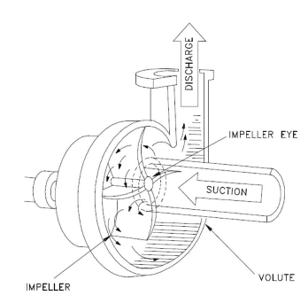
Centrifugal pumps can have multiple impeller designs, where each impeller in the series adds to the work of the previous impeller by directing the water leaving its rim to the next impeller’s eye. However, it’s important to note that these additional impeller stages do not increase the flow rate of the fluid leaving the pump, but only increase its pressure. The flow rate of a centrifugal pump is determined by several factors, including the design of the impeller, the pump case, the size of the impeller, its rim speed, the size of the waterways through the impeller, and the pump’s elevation relative to its water supply.
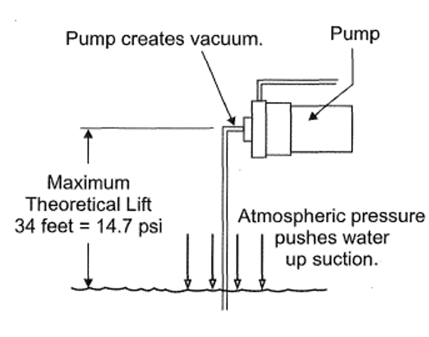
When a centrifugal pump operates, it creates negative pressure in its casing. This negative pressure, along with atmospheric pressure acting on the water surface in the well or lake, causes water to flow up the drop pipe and through the pump casing. However, the pump’s lift capability is influenced by several factors such as atmospheric pressure, friction resistance (loss) in the supply pipe, and the pump’s condition.
Centrifugal pumps have a theoretical suction lift capability of approximately 34 feet at sea level (Figure 9), based on atmospheric pressure (14.7 psia) and the weight of water per foot of height (0.433 psi/ft.hd.). However, the pump’s actual lift capability is lower due to factors such as friction loss in the suction pipe, the pump’s efficiency, and the elevation above sea level. The maximum practical suction lift for a centrifugal pump installed at sea level is typically around 25 feet.
The resistance caused by flow pressure in the opposite direction of the centrifugal pump reduces its flow output capacity. If there is excessive backpressure, it can surpass the pump’s ability to move fluid. This property is significant in centrifugal pumps, and it’s essential to understand that they are considered variable displacement pumps due to this. Variable displacement indicates that the amount of water discharged from the centrifugal pump decreases as it is asked to do more work, such as raising the height of fluid lift or increasing output pressure.
Centrifugal pumps, unlike positive displacement pumps, do not have the ability to self-prime and provide a variable flow rate that changes based on the discharge pressure. However, despite these limitations, the design and engineering of centrifugal pumps make them highly suitable for the water supply industry. In fact, they are commonly used in private water supply systems, with jet pumps and submersible pumps being the two most prevalent types. Jet pumps are surface-mounted and use suction to draw water, while submersible pumps are installed underwater and push water to the surface. Both types are reliable and efficient, making them popular choices for private water supply applications.
Jet pump
The jet pump is a type of centrifugal pump that uses the venturi effect to boost its suction. The pump incorporates a nozzle, (also known as an injector or ejector), and venturi into the inlet of the impeller housing (Figure 10). The impeller case is designed so that some of the impeller output water is diverted to a nozzle through a passage built into the pump case and the jet assembly. As the diverted water travels through the venturi tube, it creates a low-pressure zone which boosts the inlet suction. This is a continual cycle that increases the volume of water traveling to the impeller.
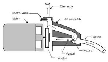
The flow control valve ensures enough water is diverted from the impeller to the jet assembly by restricting the amount of water that can flow from the outlet of the pump to achieve good pumping performance. Some manufacturers may require a separate flow control fitting to be installed on the outlet of the case. Shallow well jet pumps provide a good supply of water but they are limited to lifting no more than about 7.6 m (25′) below the pump.
Jet pumps are also available in deep well designs were the jet assembly is located in the water source. Two pipes are connected from the pump to the ejector housing (Figure 11). One delivers water to the pump and is called the suction or delivery line. The other, which recirculates water back to the ejector, is called the pressure or return line. The pump pressure supplied by the return line actually helps push water up through the suction line to the pump. The control valve must be adjusted to match the depth of the installation to ensure there is sufficient water diverted to the pressure line while still maximizing the discharge volume.
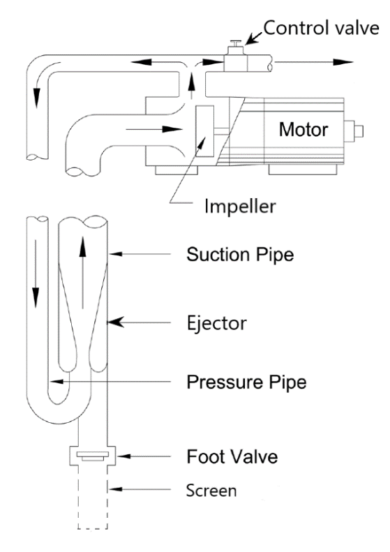
Although this combination of atmospheric and pump pressure is very effective at lifting water long distances, up to 36.7 m (120′), it results in efficiency losses at the discharge side of the pump. For the most part the use of jet pumps for deep well applications has been replaced by submersible pumps.
Submersible pumps
Submersible pumps are a type of multi-stage centrifugal pump designed to be fully submerged in the water or other fluid it is pumping. Submersible pumps commonly employed in residential wells are typically designed with a diameter of 3 5/8″ to fit comfortably within a 4″ well casing. The motor is positioned at the bottom of the pump and is housed within a stainless steel cylinder that is attached beneath the pump assembly (Figure 12). Located just above the motor is the inlet screen, which serves as the point of entry for water into the pump from the well. When the pump is turned on, the motor drives a series of impellers stacked on top of each other within a stainless steel housing . The impellers are hydraulically connected in series each one is designed to increase the pressure of the water as it passes through and into the next. A typical impeller section for this type of pump will generally increase water pressure available from the impeller by approximately 9 psi per stage. The pump is supplied with a discharge check valve to hold pressure in the system when the pump stops.
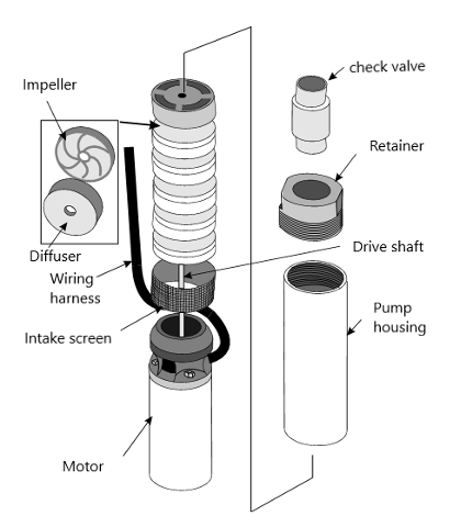
The multiple impeller design of submersible pumps enables many design options to match a wide range of applications. They can be designed with more impellers to create more pressure or impellers with a different design to deliver more volume. The horsepower of a submersible pump’s motor and the number of impellers will indicate the potential capacity and the pressure it can deliver.
Additionally, submersible pumps are compact, highly efficient, quiet, and require minimal maintenance. They are also less prone to issues such as pump cavitation and are not affected by changes in atmospheric pressure, as they are completely submerged in water.
Pump Motors
The alternating current (AC) electric motor is one of the most common drivers used on water supply pumps. Alternating current power may be single-phase or three-phase electricity, but is generally single-phase for residences and three-phase for commercial or industrial use.
Unlike three-phase motors, single-phase induction motors cannot generate their own starting torque. To overcome this issue, two sets of windings are used. The “start or auxiliary windings” create a phase shift in the magnetic fields and produce an artificial second phase, allowing the motor to generate starting torque. As soon as the motor attains a sufficient speed, the starting means may be removed depending on the type of the motor.
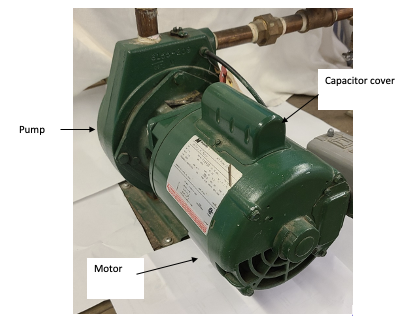
Single-phase induction motors are classified and named based on their starting method. There are various types of such motors, which include capacitor start/Induction run (CSIR) motors, capacitor start/capacitor run (CSCR) motors, split-phase induction motors, and permanent split capacitor motors. Each of these motor types has different abilities in terms of horsepower, efficiency, starting torque, and starting current. The manufacturer chooses the motor type based on the pump requirements for the specific application. For residential above-ground rural water supply the pump and motor typically comes as part of a coupled package (Figure 13). Considering the proper electrical supply requirements are provided, the starting method holds minimal significance during installation since all the necessary circuitry is self-contained within the pump motor. Jet pumps are often supplied with a dual voltage motor. They are easily switch between 115V and 230V with a change plug or dial on the motor terminal board located under the motor end cover. It is essential that the setting is checked before the power is connected to the pump.
Frequent cycling of the pump can lead damage to both the pump motor and the pressure switch contacts. This pump cycling not only causes potential harm but also creates significant disturbance for occupants within the building. To mitigate wear and tear on the pump motor, motor manufacturers recommend a minimum run cycle of two minutes for centrifugal pumps. This duration allows the pump to dissipate waste heat generated by the motor and motor starter mechanism, preventing premature failure of these delicate components. It is advisable to limit the pump cycling to no more than 25 times per hour.
Furthermore, when centrifugal pumps are installed indoors, it is crucial to ensure sufficient airflow around the motor. Maintaining proper ventilation and airflow around the motor will prevent overheating and ensure reliable pump operation. Insufficient airflow may cause the motor to overheat, activating its thermal overload motor protection.
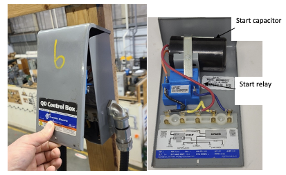
Submersible pumps will often have some of the circuit components supplied separately in an above ground mounted control box. Control boxes contain starting capacitors, a starting relay, and, in some sizes, overload protectors, running capacitors, and contactors (Figure 14).
Submersible motors
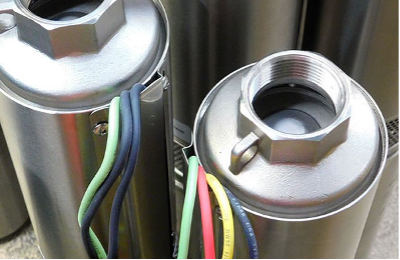
Submersible pumps typically used for residential wells are usually 3 5/ 8″ in diameter to fit inside a 4″ well casing. The motor, which looks like a stainless-steel cylinder is attached below the pump. Just above it is a screen of some type; many are made from plastic and some are made from stainless steel. This is the inlet screen of the pump and the point at which water comes into the pump from the well. Submersible motors have waterproof features to ensure that the motor winding conductors and motor leads are protected from water damage. Submersible motors come in 2 and 3-wire types. Both types have a green ground wire, which is not included in the wire count. Two-wire pumps have two black wires and a green wire, while three-wire pumps have a black, red, yellow, and green wire. (Figure 15).
Three-wire well pumps are either of the CSIR or CSCR types and have all of their starting components housed in the above ground control box. Two-wire well pumps, on the other hand, are of the permanent split capacitor or split phase types and do not use a separate control box because all the starting elements are built within the motor or pump housing. However, the horsepower rating of 2-wire motors is limited to around 1 ½ hp because larger horsepower motors require more capacitance to operate. While manufacturers indicate there is little difference in failure rates between the different types, 3-wire types seem to be preferred by industry because the starting components are located outside of the well, making them easily accessible for testing and replacement.
Permanent Magnet Synchronous Motors (PMSMs)
A Permanent Magnet Synchronous Motor (PMSM) generates a magnetic field using permanent magnets, as opposed to traditional electromagnets in the rotor. The rotor runs synchronously to the switching AC current due to the permanently magnetized magnets. Since induction motor slippage is not necessary, PMSMs can provide more accurate speed control and consume less energy. Unlike induction motors, PMSMs do not require separate start windings but rather rely on an electronic variable frequency drive for operation.
Variable Frequency Drives (VFDs)
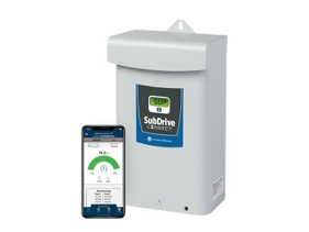
A VFD is an electronic device that controls the speed of an AC motor by varying the frequency of the power supplied to the motor. Decreasing a pumps speed has a huge impact on the required motor output. By adjusting the frequency of the power supplied to the motor, a VFD can vary the speed of the motor, allowing it to operate at a more efficient level. VFDs also allow the motor to gradually ramp up to meet the actual flow and pressure demand, this soft start capability increases the motor life. Rural water supply pumps with VFDs are often referred to as constant pressure pump systems (Figure 16) because they have the capability to slow down the motor and the pump speed according to the required demand, leading to increased efficiency and reduced energy consumption.
Although VFDs can enhance the efficiency of single-phase induction motors, Permanent Magnet Synchronous motors (PMSMs) are entirely reliant on VFDs for operation. The use of PMSMs in conjunction with VFDs is not a new concept, and more design engineers and equipment owners are installing permanent magnet motor systems for well and booster applications due to their smaller size and superior efficiencies.
Pressure System Components
The pressure system components encompass the entirety of equipment, fittings, and piping employed to convey water from the well or water source to the household water supply lines. The specific components utilized depend on the type of pump and the requirements of the particular installation. Familiarizing oneself with the functionality of each part within the complete pump system and exploring the available alternatives, assists in selecting the appropriate equipment, pipe, and fittings required for the task.
Foot Valve
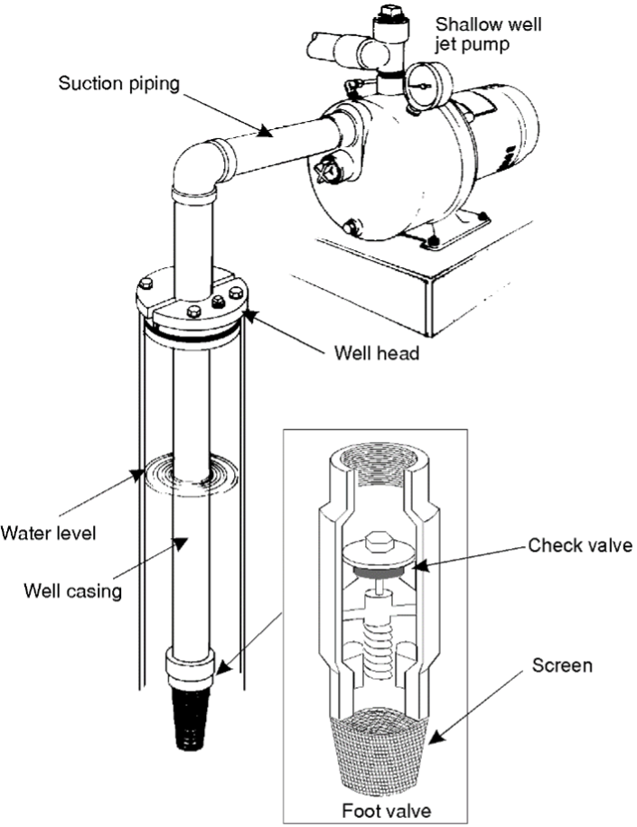
A foot valve is a type of vertical lift check valve with NPT connection on the outlet side and a strainer on the inlet side. The addition of the strainer prevents large pieces of debris from clogging the foot valve while it’s in the open position, also avoiding damage to the water pump. (Figure 17).
Foot valves are used in shallow well jet pump and deep well jet pump installations. They are installed onto the end of a pump suction line to hold water in the suction line so that the pump remains primed while not in operation. When the pump starts, and a vacuum is created inside the suction piping, the valve opens and water from the well or lake flows into the pipe. When the pump stops, and pressures equalize across the pump, the valve closes. Some foot valves have a lightly spring-loaded disc and others are simply a weighted disc, it is best to install the foot valve in the vertical position for most efficient operation.
Inline Check Valves
Submersible pumps do not use foot valves; instead a check valve is usually built into the discharge side of the pumps. If the pump does not have a built-in check valve, a spring-loaded inline check valve should be installed in the discharge line within 7.6 m (25 ft) of the pump and below the drawdown level of the water supply (Figure 18). The check valves on a submersible pump is used to hold pressure when the pump stops. They are also used to prevent backspin, water hammer and upthrust. Any of these or a combination of them can lead to immediate pump or motor failure, a shortened service life or operating problems in the system.
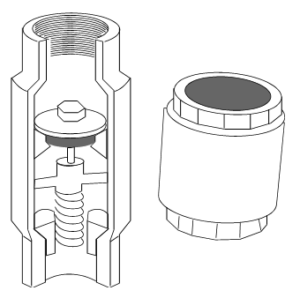
For pump settings 60 m (200 ft) or deeper, manufacturers often recommend the installation of additional spring-loaded inline check valves at regular 60 m (200 ft) intervals towards the wellhead. This setup helps reduce hydraulic shock on the system caused by starts and stops. Incorporating multiple check valves enables the system to absorb and diminish shock effects both above and below each check valve, thereby safeguarding the lifespan of valves, pump, and pipes. Furthermore, some manufacturers may require an extra check valve positioned above ground, typically near the pressure tank. Strict adherence to the manufacturer’s specifications regarding check valve requirements is of utmost importance. However, exceeding the recommended number of check valves must be avoided, as it can result in unforeseen complications.
Riser Pipe (Pump Drop)
Different materials are used for well pump pipe risers, each with its own characteristics and suitability for specific applications. One of the greatest variable costs that a well owner has is the labor paid for the installation and removal of their well pump and motor. To minimize this cost over time, it is important to choose drop pipe that will last while also considering the ease of installation and removal.
The main factors to consider are weight limitations, depth limitations, flow restriction, water composition, ease of installation, and ease of removal. The deeper the pump setting, the more important it is to pay attention to the pipe manufacturer’s recommendations as to the maximum depth allowable for the size and schedule of the riser pipe, the maximum horsepower allowable, and the type of couplings and check valves to use.
Here are some commonly used materials and their characteristics:
Polyethylene pipe is a durable and flexible material often used for well pump pipe risers. It has excellent resistance to corrosion, abrasion, and chemicals. Polyethylene risers are one of the most popular materials used for pump risers as they are a lightweight, continuous section without any connections, making them easy to install by hand. Polyethylene pump drop is sold in 160 psi or 200 psi pressure ratings, and size ranges from 1” -2 IPS to fit barb insert fittings. It is available in 100 -1000 ft coil lengths. Due to its maximum pressure rating, polyethylene pipe is not recommended for installation over 300 ft. in depth.
Polyvinyl Chloride (PVC) is widely chosen for well pump pipe risers due to its cost-effectiveness, resistance to corrosion, and ease of installation. It is a lightweight and durable material with excellent chemical resistance. Pre-threaded PVC drop pipes are available in various sizes, ranging from 1″ NPT to 2″ NPT, and come in 20 ft lengths of Sch 80 and Sch 120. This versatility enables their use in different pump setting depths, system pressures ranges, and pump ratings. Be sure to following the manufactures guidelines for instance; PVC Sch 120 1 ¼” drop pipe is generally recommended for systems with a maximum depth of 520′ and a pump rating of up to 2.0 HP. It is important to be aware that PVC can gradually become brittle over time and may be prone to damage from extreme temperatures or physical impact. Care should be taken to protect PVC risers from such factors to ensure their longevity and reliable performance.
Galvanized steel risers offer good strength and durability, making them suitable for greater well depths and environments. Galvanized steel risers can handle high pressures and temperatures. However, over time, the zinc coating may degrade, leading to corrosion also their rigidity makes installation more challenging than PVC or HDPE.
Stainless steel risers offer superior strength, durability, and resistance to corrosion. They are highly suitable for corrosive environments or wells with high mineral content. Stainless steel risers are available in different grades and can withstand high pressures and temperatures. They have a long lifespan and require minimal maintenance and are suitable for greater well depths. However, stainless steel risers tend to be more expensive compared to other materials.
Stainless steel and Galvanized drop pipes are capable of going to almost any depth as they have the highest pressure ratings. In fact, the check valves used will normally be the first thing to limit the depth in the system. For example, a commonly used brass check valve is rated for about 600 feet and a ductile iron check valve is rated for about 1500 feet.
Torque Arrestors
All plastic drop pipes for a submersible pump should be equipped with a torque arrestor (Figure 19) to keep the submersible pump centred and control flexing movement of the pipe caused by the pump starting and stopping. As the pipe flexes, it may contact the interior of the well casing and cause premature wear of the drop pipe. The torque arrestor controls this movement to keep the pipe from wearing against the casing.
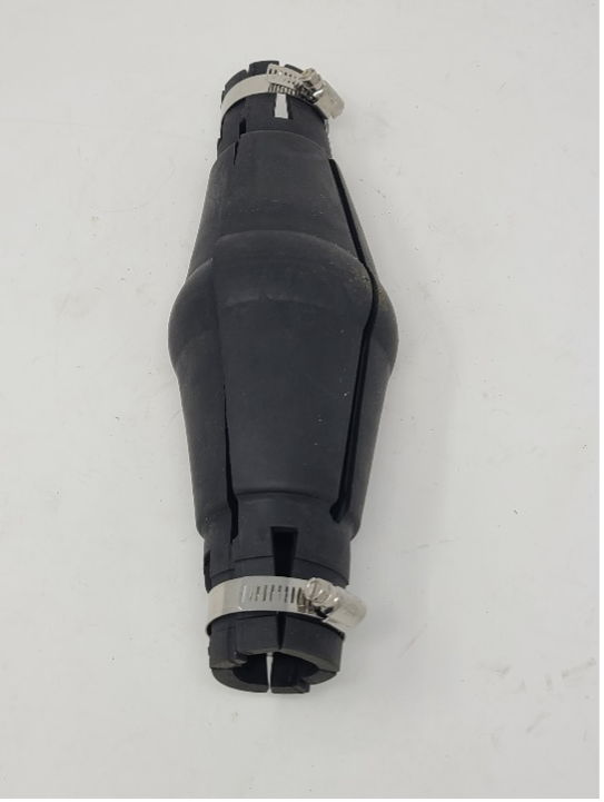
Follow the manufacturer’s instructions for arrestor spacing, number required and method of attachment to the drop pipe. Usually, installations using galvanized or stainless pipe do not require a torque arrestor since the pipe does not flex due to the torque, but pump manufactures still recommend the use a torque arrestor at the pump, as a centralizer for the pump to ensure proper motor cooling and reduce inlet turbulence.
Safety Rope
A safety rope is connected directly to the submersible pump and secured at the well head. The safety rope provides a backup to enable the installer to pull the pump from the well if the riser pipe fails. Every pump should have a safety rope secured to it before hanging it in the well.
Pitless Adapter
If the well head is not equipped with a well house to protect it from the elements then a pitless adapter should be installed (Figure 20). A pitless adapter is a special type of fitting that allows supply piping to connect to the well casing below the frost level. Its main purpose is to allow access to the water supply from the well without the need for a traditional well pit or underground chamber.
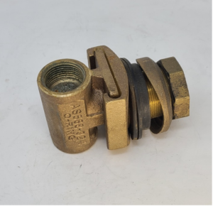
It allows the water pipe to pass through the well casing sidewall horizontally. This horizontal connection eliminates the need for a vertical pipe extending above the ground, which is a common feature in traditional well pits. It provides a watertight seal between the well casing and the drop pipe.
The second major advantage of these adapters is they provide ease of installation and removal of pumps or lines from the well. The inner well portion of the adapter has removeable elbow with a dead end threaded tapping on the top. This enables a lift out pipe to be connected to the adapter, to reach into the well and lift the riser pipe and pump assembly. The saddle clamp is designed to fit and seal the full range of casing sizes.
Well Caps and Seals
The top of the water well must be protected from debris and contaminants entering the well. Both well caps and seals are designed to cover the top of a water well and, in effect, enclose the well casing so that the well is protected. They provide an access point where supply piping and pumps can be attached and enable access to the well for maintenance and repairs . There are a variety of caps and seals to match the different applications.
Caps
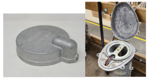
A well cap is cover that sits on top of a well casing, like a lid it is seated along the top and outer edges of a well casing (Figure 21 left). Caps are used when a pitless adapter is installed below the frost line and do not support the pump. Well caps provide venting for the well are often designed with the ability to allow pump wire to pass through underneath the lid (most often via conduit) and there is often a grounding bolt also included. For exposed applications there are watertight types (Figure 21 right) that are sealed all the way around the casing and conduit with a separate vent screens added, to allow the well to breath but keeps vermin out.
Seals
A well seal is utilized when the drop pipe can extend above ground level, providing several functions beyond those of a well cap. Positioned on top of a well casing, the well seal enables the passage of pump wire and water supply through designated holes in its design. Figure 22 displays a single-hole well seal on the left, suitable for installing either a shallow well jet pump or a submersible pump. In addition to the centre drop pipe hole it features two threaded tappings; one for venting and the other for accommodating cables in submersible pump installations. The image on the right shows a double-hole well seal designed for deep well jet pump setups, enabling two pipes to descend into the well. Notably, the double-hole variant only includes a vent tapping, as a power cable tapping is unnecessary for jet pump installations.
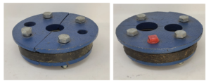
The top plate of a well seal is seated along the top and inside edges of a well casing. When the bolts are tightened the two halves draw together causing the rubber seal to expand out towards the inside of the well casing and the outside of the discharge pipe creating a watertight seal.
Well seals are commonly constructed from materials such as cast iron, plastic, cast aluminum, and steel. The selection of materials is contingent upon the depth and size of the pump, ensuring that the seal possesses the necessary strength to support the estimated weight of the pump, drop pipe, cable, and water column.
Pressure Tanks
A pressure tank is a vital component in pumped water supply systems, designed to maintain consistent water pressure and reduce the frequency of pump operation. Because water is noncompressible, there needs to be some method in place to provide usable pressure without the pump running, when small amounts of water are drawn from the system. The pressure tank acts as a buffer or reservoir, storing pressurized water for immediate use when the demand arises.
The primary purpose of a pressure tank is to prevent rapid cycling of the pump, known as short cycling, which can cause premature wear and tear, and affect the system’s efficiency. When a pump starts, it rapidly builds up pressure and delivers water to the tank until a predetermined level is reached. This level is typically controlled by a pressure switch. As water is drawn from the system, the pressure drops, triggering the pump to restart, refilling the tank while also pushing some water to the system to meet any momentary fixture demand. By storing a reserve of pressurized water, the pressure tank reduces the frequency of pump cycling, allowing the pump to run less frequently and for longer durations, which increases its lifespan.
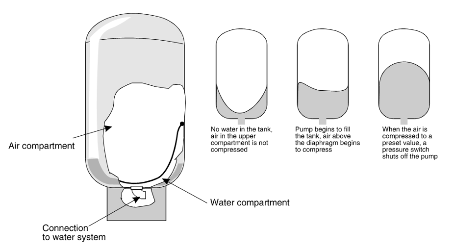
The operation of a pressure tank is based on the principles of air and water separation. Inside the tank, there is a flexible bladder or diaphragm that divides the tank into two compartments: one for water and the other for compressed air (Figure 23). When the pump fills the tank with water, the air inside the tank is compressed further, increasing the pressure. This compressed air acts as a cushion, exerting pressure on the water and maintaining a consistent pressure in the system even when the pump is not running.
As water is drawn from the tank, the compressed air expands, pushing the water out and maintaining a steady flow until the pressure drops to a specific low-pressure threshold. At this point, the pressure switch signals the pump to restart and refill the tank to the predetermined pressure point.
Notice on the diaphragm pressure tank shown in Figure 23 the flexible diaphragm attached to the inner sides of the tank. A bladder pressure tank uses a balloon-type flexible membrane that is attached to the inlet/outlet connection to the tank, essentially creating a bag that that the water is stored in. The advantage of a bladder tank is that no water comes in contact with the tank itself. This is particularly helpful if the water has corrosive properties.
Both bladder and diaphragm tanks are precharged and have an air charging (Schrader, Snifter) valve, at the top. Tanks are made of steel or a light weight fibreglass composite.
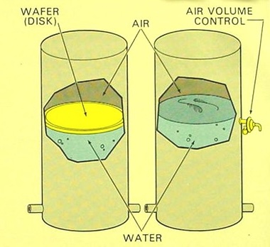
Traditional pressure tanks of older designs lacked a bladder or diaphragm, resulting in direct contact between air and water within the tank (Figure 24). This direct contact causes a gradual absorption of air molecules by the water over time, a phenomenon known as waterlogging. Waterlogging leads to increased pump cycling, with more frequent cut-ins and cut-outs. Although some tanks incorporated a plastic disk to separate the air and water, its effectiveness varied. Pressure tanks with air-water contact necessitate periodic air injections to maintain the required air volume. Various air-volume control mechanisms are available, which introduce fresh air into the system during pump operation. Additionally, such tanks have the drawback of being incapable of being pre-charged with compressed air. Consequently, they require larger tank sizes compared to pre-charged diaphragm or bladder style tanks to achieve an equivalent reserve of usable water, also known as drawdown capacity.
Without a pressure tank the pump would have to tum on every time there is even the slightest demand on the system, even to fill a small glass of water. It can be inferred that the size of the pressure tank directly impacts the availability of usable water and the frequency of pump operation. Larger tanks provide a greater water supply while minimizing pump cycling, but they come at a higher cost and require more space. Conversely, smaller tanks offer cost and space advantages, but they may lack sufficient water reserve. Undersized tanks exhibit undesirable characteristics such as frequent pump cycling, leading to pump wear and unnecessary energy consumption. Additionally, they may fail to meet peak load demands when multiple faucets are in use simultaneously. Achieving a reliable and practical system necessitates a careful balance of these factors. In Learning Task 2, we will explore methods to calculate the optimal tank size, considering variables such as the pump’s flow rate, desired pressure range, and usage patterns.
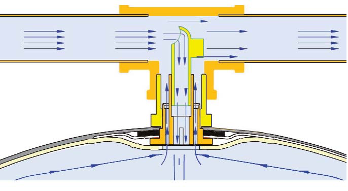
In VFD constant pressure systems, the pumps are specifically designed to handle frequent starts and stops without harming the motor. Consequently, the pressure tank does not need to provide extensive water storage or manage extended periods of demand. Instead, its role is primarily to dampen sudden pressure surges and compensate for any slight delay in pump shutoff and the initial start-up. Due to the reduced requirements for water storage and demand management, the pressure tank in VFD constant pressure systems can be compact in size. Its purpose is more focused on maintaining system stability and preventing pressure fluctuations rather than providing a significant reserve of water. VFD water systems will operate at a very low pressure differential therefore the water within the pressure is not completely flushed each cycle like a conventional system. The water that can remains in the pressure tank for extended periods of time can stagnate. This stagnate water may get drawn out of the tank and noticed by the users at times when there is a large initial flow surge or a power outage. To eliminate stagnate water accumulation within a pressure tank, serving a constant pressure VFD system, there are specially designed pressure tanks in which the water will continuously flow through them. These tanks have a special tank tee that diverts system water into, and more importantly out of the tank while the pump is running (Figure 25). This constant flushing action ensures that the water in the tank remains fresh.
Pressure Switch
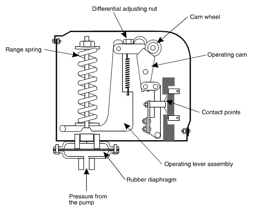
A pressure switch monitors the pump discharge pressure and controls the electrical power supply to the pump. As stated earlier, is works in tandem with the pressure tank to maintain consistent water pressure and optimize the frequency of pump operation. A small, box-like unit, the pressure switch has a built-in flexible diaphragm that moves back and forth reacting to the water system pressure (Figure 26). The movement of the diaphragm opens and closes a set of contact points that control the power to the pump motor. This is a snap-acting switch, so the electrical contact points are quickly opened.
All Pressure switches have two operating thresholds known as the cut-in (Reset Point) and cut-out (Trip Point) settings. The cut-in point is for the falling pressure where the pump will be started, and the cut-out point is for the rising pressure when the pump will be stopped. The standard pressure differential between these two points is 140 kPa (20 psi). Pressure switches are available from the manufacture at pre-set ranges of:
- 140 kPa (20 psi) pump cut-in and 280 kPa (40 psi) pump cut-out
- 210 kPa (30 psi) pump cut-in and 345 kPa (50 psi) pump cut-out
- 280 kPa (40 psi) pump cut-in and 410 kPa (60 psi) pump cut-out
Both the entire range and the differential can be adjusted.
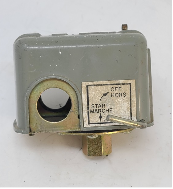
Some Pressure switches come with a low pressure cut-off to protect the pump (Figure 27). It is set at 10 psi. and shuts off the pump in the event of an abnormally low system pressure. These switches will have a manual reset lever which allows the pump to be run, and build up pressure, once the problem is resolved.
VFD constant pressure systems do not use these types of conventional pressure switches instead they use electronic transducers as pressure sensors.
VFD Pressure Sensor/Transducer
A pressure transducer, also known as a pressure sensor (Figure 28), is a device that converts the mechanical force exerted by the fluid into an electrical signal. In a VFD system the pressure transducer continuously monitors the pressure and sends the corresponding electrical signal to the VFD controller. The VFD controller then adjusts the motor speed, based on the signal received from the pressure transducer, to maintain a constant pressure setting.
Mascontrol
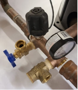
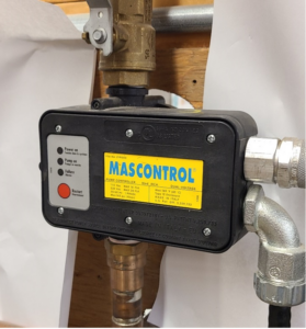
The Mascontrol is a type of self-contained constant pressure device designed to replace both the pressure tank and the pressure switch (Figure 29). This control has a diaphragm switch that reacts to pressure change and energizes the pump. It will operate the pump whenever there is a demand on the system. The reasoning behind this device is that the pump will accumulate less starts if it operates on demand rather than recharging the pressure tank multiple times for long usage cycles. This reasoning is dependent on the type of water usage. For example, does the user have a lot of long run applications, such as irrigation, that would require multiple pump starts with a conventional tank system. The Mascontrol is not a VFD as the pump runs at full speed when activated, the constant pressure output is controlled by an integral flow valve. It also has low pressure switch to protect the pump against dry running.
Pressure Relief Valve
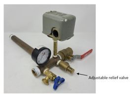
The submersible pump you choose may have the ability to generate higher pressure than what the pressure system components can withstand. For this reason, manufacturers of submersible pumps recommend the installation of a pressure relief valve. This relief valve is typically set at 10 psi above the cut-out pressure of the pressure switch, offering protection against overpressure in the system in case the pressure switch malfunctions.
To facilitate the installation of the relief valve, as well as the pressure switch, pressure gauge, and drain valve, a manufactured tank tee (Figure 30) provides a convenient connection point. This tank tee serves as a practical and efficient solution for incorporating these components into the system.
 Now complete Self-Test 1 and check your answers.
Self-Test 1
Self-Test 1
Media Attributions
- Figure 1. “Hydrological cycle” by Sunson08 on Wikimedia Commons is licensed under a CC BY-SA licence.
- Figure 2. “Ground water” – The source for this image is unknown. It is being used for non-commercial, educational purposes. To receive credit for this image, please reach out to the publisher.
- Figure 3. “Dug well” from the Ontario Ministry of Agriculture, Food and Rural Affairs is used for educational purposes under the basis of fair dealing.
- Figure 4. “Driven well” from SkilledTradesBC is used for educational purposes under the basis of fair dealing.
- Figure 5. “Well components” – The source for this image is unknown. It is being used for non-commercial, educational purposes. To receive credit for this image, please reach out to the publisher.
- Figure 6. “Hand pump” by Manco Capac on Wikimedia Commons is licensed under a CC BY-SA 3.0 licence.
- Figure 7. “Reciprocating piston pump” from SkilledTradesBC is used for educational purposes under the basis of fair dealing.
- Figure 8. “Centrifugal pump” from NTGD Pump is used and adapted for educational purposes under the basis of fair dealing.
- Figure 9. “Theoretical suction lift” – The source for this image is unknown. It is being used for non-commercial, educational purposes. To receive credit for this image, please reach out to the publisher.
- Figure 10. “Shallow well jet pump operating principle” from Alberta Agriculture and Rural Development is used for educational purposes under the basis of fair dealing.
- Figure 11. “Deep well jet pump principle” by Camosun College is licensed under a CC BY-SA licence.
- Figure 12. “Submersible pump parts diagram” from SkilledTradesBC is used for educational purposes under the basis of fair dealing.
- Figure 13. “CSIR motor and pump package” by Rod Lidstone is licensed under a CC BY-SA licence.
- Figure 14. “Submersible pump control box” by Rod Lidstone is licensed under a CC BY-SA licence.
- Figure 15. “Two wire and three wire submersible pumps” by Camosun College is licensed under a CC BY-SA licence.
- Figure 16. “Franklin Electric SubDrive (VFD) with phone app” from Franklin Electric is used for educational purposes under the basis of fair dealing.
- Figure 17. “Foot valve” from SkilledTradesBC is used for educational purposes under the basis of fair dealing.
- Figure 18. “Inline check valve” from SkilledTradesBC is used for educational purposes under the basis of fair dealing.
- Figure 19. “Torque arrestor” by Rod Lidstone is licensed under a CC BY-SA licence.
- Figure 20. “Pitless adapter” by Rod Lidstone is licensed under a CC BY-SA licence.
- Figure 21. “Well caps” by Rod Lidstone is licensed under a CC BY-SA licence.
- Figure 22. “Well seals” by Rod Lidstone is licensed under a CC BY-SA licence.
- Figure 23. “Diaphragm pressure tank operation” from SkilledTradesBC is used for educational purposes under the basis of fair dealing.
- Figure 24. “Standard pressure tanks” – The source for this image is unknown. It is being used for non-commercial, educational purposes. To receive credit for this image, please reach out to the publisher.
- Figure 25. “Flow-Thru pressure tank connection” from Flexcon Industries is used for educational purposes under the basis of fair dealing.
- Figure 26. “Pressure switch” from SkilledTradesBC is used for educational purposes under the basis of fair dealing.
- Figure 27. “Pressure switch with low pressure cut-off” by Rod Lidstone is licensed under a CC BY-SA licence.
- Figure 28. “VFD pressure sensor” by Rod Lidstone is licensed under a CC BY-SA licence.
- Figure 29. “Mascontrol pump controller” by Rod Lidstone is licensed under a CC BY-SA licence.
- Figure 30. “Tank tee” by Rod Lidstone is licensed under a CC BY-SA licence.

