Competency C1: Install Rural Water Supply Systems
Learning Task 5
Describe Service and Maintenance of Water Supply Pressure Systems
The service and maintenance of well pump systems are essential for ensuring a reliable water supply, as even high-quality pumps designed to last 15 to 20 years can encounter issues over time. The stresses endured during water transportation and delivery can gradually wear down even the most efficient pumps and motors. Operating problems will occur in most installations, necessitating careful investigation and repair or replacement of worn or damaged parts. Troubleshooting these well pump issues demands a combination of knowledge about the system's operating principles, keen instincts, and technical expertise to effectively address and rectify any challenges that may arise. Regular upkeep and attentive problem-solving are key to prolonging the lifespan and optimizing the performance of well pump systems.
Maintenance
Fortunately, proper placement and the movement of relatively clean fluids translate to minimal and infrequent maintenance issues for contemporary pumps. Instances that lead to pump complications encompass:
- Operating the pump close to its designated parameters for water quantity or maximum head,
- Employing the pump for tasks outside its intended applications.
Such scenarios impose a typical strain on the pump, rendering its expected operational life nonstandard. For instance, a pump tasked with handling sand will inevitably exhibit a shorter lifespan compared to a pump dealing with clear water. Similarly, a pump that operates at maximum head may not be able to move water at all if the tolerances between its impeller and diffuser change because of wear.
As the pump wears, the motor current increases, until eventually the overloads trip to protect the motor. Proper care of a submersible installation should include periodic check-ups to avoid interruptions in the water supply. Manufactures recommended checking the motor's insulation resistance every six months. When the insulation resistance falls below 10 megohms, check it frequently for further deterioration and pull the pump when the resistance falls to 0.5 megohm or below.
Several types of gauges and instruments are used to check the efficient operation of pumps:
- a pressure gauge can be used to check proper rotation of a three-phase motor
- vacuum gauges can be used to check that the pump is developing sufficient pressure differentials
- a multimeter is an invaluable tool for example:
- the ohmmeter allows you to quickly pinpoint the problem when you encounter difficulties in starting motors
- the clamp-on ammeter can be used to detect current imbalance
- and the voltmeter can be used to match the motor voltage to your supply voltage
Since modern pump motors are electrical, many problems you encounter will require you to be familiar with electrical test instruments. Always refer to manufacturer's detailed instructions when testing the efficient operation of your pump and motor.
In British Columbia a plumber must hold a valid electrical licence to modify any wiring on pumps.
Preliminary Troubleshooting Tests
Complete these tests before removing the motor from the well or other location. These tests are for all sizes, including single- and three-phase.
- Line-to-Line voltage (Nameplate +/-10%)
- Amperage in all motor wires
- Line-to-Ground insulation resistance
- Line-to-Line winding resistance
Voltage Measurements
- Ensure the motor is off.
- Measure voltage supply at pressure switch or line contactor. For single phase motors, measure between line and neutral. For three-phase motors, measure between the legs.
- Ensure the voltage reading is ± 10% of motor rating.
- Turn the motor on until it is running normally.
- Measure voltage at load side of pressure switch or line contactor with pump running.
- Ensure the voltage reading remains the same except for slight dip on starting. Loose connections, bad contacts, ground faults, or inadequate power supply can cause excessive voltage drop.
- Either low voltage or ground faults cause relay chatter.
Current (Amp) Measurements
When the pump is running, is the motor drawing enough amperage to indicate it is doing some work, or is it drawing maximum amperage, indicating maximum working conditions? A bound pump causes locked rotor amps and overloading tripping. Pump running at shut-off pressure, worn pump, or stripped drive shaft splines may cause low amps. Use a clamp-on style ammeter to measure current on all motor leads (Figure 69).
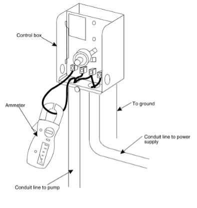
Single phase submersible measurements at the control box include:
- Ensure current in red lead is momentarily high, then drops within one second to manufactures specifications. This verifies relay or solid state relay operation. Relay or switch failures cause red lead current to remain high and overload tripping.
- Check current in black and yellow leads does not exceed manufactures specifications. Open run capacitor(s) cause amps to be higher than normal in the black and yellow motor leads and lower than normal in the red motor lead.
Check three-phase motor current imbalance
For three phase motors currents in the individual phases must be approximately equal:
- Individually clip your ammeter to each leg at the control box or starter to measure and record the amps on each leg.
- If there is considerable difference between the legs disconnect the power and change all three connections at the starter. Be careful to shift the leads (not changing the order) so the rotation remains the same. Restart the pump, then measure and record the current on each leg.
- Disconnect the power and shift the cable leads for a third set of readings.
- Select the most consistent set of readings and find the average of the three amp values.
- Compare each single leg reading from that set to the average to identify the leg that had the greatest amp difference from the average.
- Divide the greatest difference by the average to obtain the percentage of unbalance, as shown in the example below.
EXAMPLE:
Phase 1 54.0 amp
Phase 2 55.0 amp
Phase 3 60.0 amp
Average: 56.3 amp
[latex]\% \text{ Unbalance} = \frac{(60 - 56.3) \times 100}{56.3} = 6.6\%[/latex]
Should the unbalance exceed 5%, first check voltage balance between the incoming lines. If the incoming power is balanced then you may have one of the following:
- burnt contacts on the motor starter
- loose terminals in starter or control box
- cable defects
- motor windings have shorted
- pump is damaged
Line-to-Ground Insulation Resistance Measurements
Use an ohmmeter or megohmmeter (megger) to the motors insulation resistance:
- Open master breaker (lockout) and disconnect all leads from control box or pressure switch to avoid electric shock hazard and damage to the meter
- Use a megohmmeter set to 500 Volt (1000 Volt maximum).
- If using an ohmmeter, set to R X 100k. Zero the meter.
- Connect one meter lead to any one of the motor leads and the other lead to the ground wire, metal drop pipe, or metal well casing (Figure 69). Repeat and records readings for each motor lead.
- If the drop pipe is plastic, connect the meter lead to ground
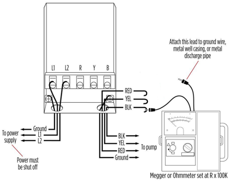
- Insulation resistance varies little with rating. Motors of all hp, voltage, and phase rating have similar values of insulation resistance. The table in Figure 71 shows typical manufacture recommend readings
- If the ohms value is normal, the motor is not grounded and the cable insulation is not damaged.
- If the ohms value is below normal, either the windings are grounded or the cable insulation is damaged. Check that the cable insulation at the well seal is not being pinched
| Condition of motor & leads | In well? | Megohm Value | Ohms Value |
|---|---|---|---|
| A new motor (without drop cable) | No | 200.0 (or more) | 200000000 (or more) |
| A used motor which can be reinstalled in well | No | 10.0 (or more) | 10000000 (or more) |
| *New motor | Yes | 2.0 (or more) | 2000000 (or more) |
| *Motor in good condition | Yes | 0.50 - 2.0 | 500000 - 2000000 |
| *Insulation damage (locate and repair) | Yes | Less than .50 | Less than 500000 |
NOTE: *Readings are for drop cable plus motor
Line-to-Line Winding Resistance
Use an ohmmeter to test condition of the motor windings and circuits:
- Open master breaker (Lockout) and disconnect all leads from control box or pressure switch to avoid electric shock hazard and damage to the meter.
- Use a multi-meter set to 20 ohms or an ohmmeter set to R X 1 for values under 10 ohms. Use next scale up for values over10 ohms. Zero the meter.
- On 3-wire motors measure the resistance of yellow to black (main winding) and yellow to red (start winding) (Figure 72).
- On 2-wire motors measure the resistance from line-to-line.
- For three-phase motors measure the resistance line-to-line for all three combinations.
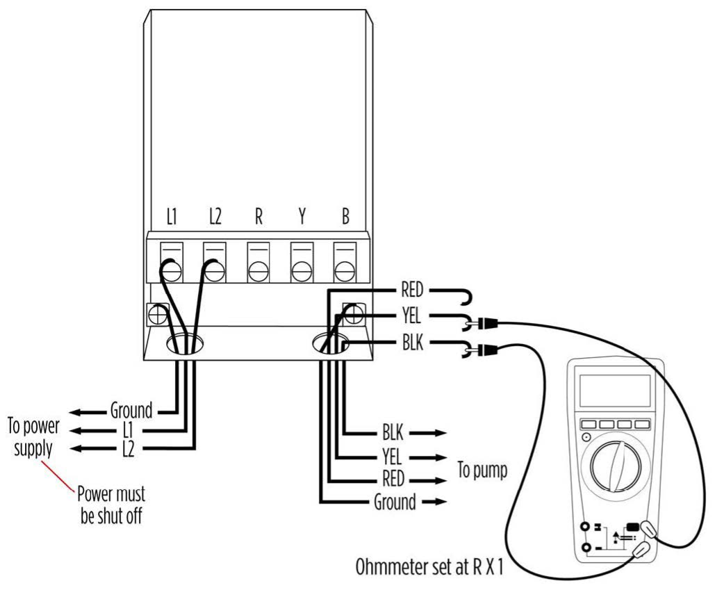
Figure 72. Motor winding test
- Compare the reading to the manufacture’s specifications. These values are often supplied on the label located under the control box cover (Figure 73). Notice these reading are for the resistance of the motor only. The resistance values for different drop cable are readily available and will need to be added to the motor winding values to compare to the actual readings.
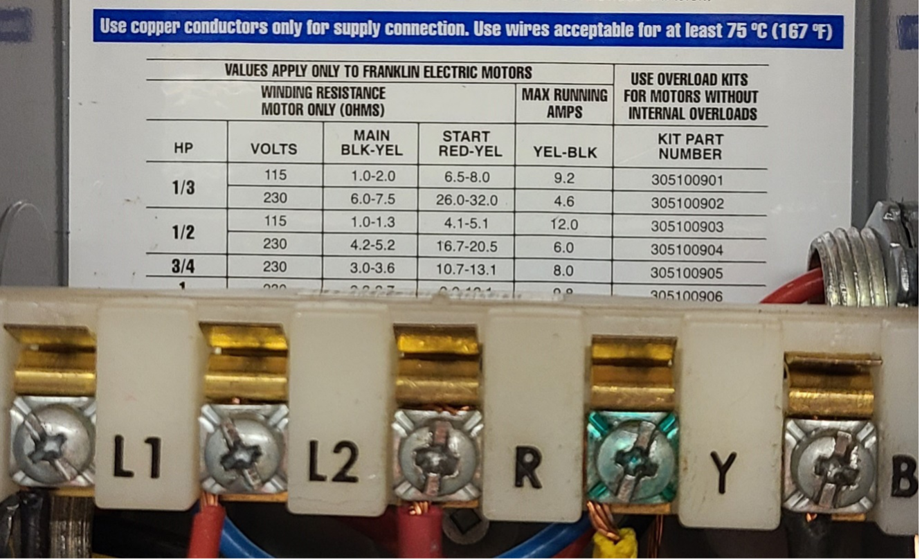
Figure 73. Control box connections and label - If all ohms values are normal the motor windings are neither shorted nor open, and the cable colors are correct (not mixed).
- If any one value is less than normal, the motor is shorted.
- If any one value is greater than normal, the winding or the cable is open, or there is a poor cable joint or connection.
- If some ohms values are greater than normal and some less on single-phase motors, the leads are mixed. This could have occurred when the leads were spiced, refer to the manufacture instruction on how to use an ohm meter to identify cables with an ohmmeter.
Additional Tests
Here are some additional tests that may need to be performed as part of a pump performance check or system troubleshooting.
Flow (Bucket) Test
The actual flow rate of the water supply system should be checked at initial installation as well as part of a troubleshooting process. Two distinct flow test procedures are employed, depending on whether the pump has been integrated into the building's plumbing system or not. The bucket test is a very useful and "low tech" test method. It consists of simply timing the filling of a vessel of known volume, and doing the math to determine a flow rate. The unit of US gallons per minute is used as that is the unit most often quoted in the pump specifications. You will need a stop watch a 5 US gallon bucket with marked increments.
If you are performing a flow test before the pump supply has been connected to the building plumbing then follow these steps:
- Measure the amount of time (seconds) it takes to fill the bucket
- Divide the gallon size of the bucket by the number of seconds it took for the bucket to be filled, then multiply by 60. This will give you the flow rate measured in gallons per minute (gpm).
When conducting the flow test with the pump linked to the building plumbing, an alternative approach is required. Merely timing the bucket's filling duration is insufficient due to water replenishment of the pressure tank while the pump is active.
If you are performing a flow test of a water supply system with a pressure tank and on/off pressure switch then follow these steps:
- Locate the pressure switch and tank. For this test you will need to know when the pump starts and stops. For a jet pump system this will be obvious as you will be able to hear the pump, whereas for a submersible you will need to listen to the pressure switch contactors. It may be easier to observe the pressure switch with the cover removed.
- Make sure the pump is not running and no water is flowing anywhere in the building.
- Open a faucet to drain water from the system the drain hose bib at the tank tee works best. As soon as the pump turns on, close the faucet so that the pump can fill up the pressure tank. Once the pump has turned back off, begin the next step.
- Open the faucet into a five-gallon bucket and have the stop watch ready for the next step. If the system has a large pressure tank you may need more than one bucket. Measure the entirety of the water discharge before the pump turns back on.
- As soon as the pump turns on, shut the faucet and use a stopwatch to time the pump cycle. Make a note of the pump cycle time (round to the nearest second) once the pump has turned back off.
- You now know the time it takes for the pump to recharge the pressure tank, and you know the acceptance volume of the pressure tank, so you can calculate the average pumping rate as follows:
[latex]\text{Averaged Pumping Rate (GPM)} = \left(\frac{\text{Volume}}{\text{Recharge Time}} \right) \times 60[/latex]
For example:
- Recharge Time = 30 seconds
- Volume = 4 gallons
- [latex]\text{Averaged Pumping Rate} = \left(\frac{4}{30}\right) \times 60[/latex]
= 8 gallons per minute
* The expression Averaged Pumping Rate refers to the fact that the pump will be running at different head pressures during the pump cycle. Therefore, the calculated bucket test flow rate will represent the average of the pumps performance over the full range of the pressure switch settings.
Isolating Leakage in Cable and Splices
As was previously mentioned if the insulation resistance of a submersible pump is below 0.5 megohms, you will need to removed the pump from the well and locate and repair the problem.
When pulling the pump, either coil the cable on a reel or raise it from the ground to dry. Check the insulation again when the cable and splices are dry. if the insulation reading remains low, disconnect the motor from the cable and check the motor separately. Should the motor be defective, check the pump end for wear and obtain a replacement for either the motor alone, or the pump unit, as necessary. However, if the insulation value between the line and motor casing increases to 50 megohms or more the problem is in the cable. You will need to isolate the fault in the cable or the splice and make the necessary repairs.
The procedure for using an ohmmeter to locate a cable leak is as follows:
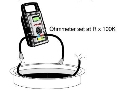
- Submerge the cable and splice in a steel barrel of water with both ends out of water (Figure 74).
- Set the ohmmeter selector knob on R X 100 K and adjust the needle to zero (0) by clipping the ohmmeter leads together. Then ground one lead by attaching it to the metal tank. Clip the other to the various cable leads in turn at one end of cable. Be sure the other end of the cable remains out of the water and dos not contact the tank.
- If the needle deflects to zero (0) on any of the cable leads, starting pull the cable out of the water slowly until the needle falls back to infinity, or no reading. When the needle falls back the leaking portion of the cable is just above water level.
Checking and Adjusting Pressure Switch
Mechanical pressure is a relatively simple electrometrical device which contains a diaphragm that presses against a piston and springs to open or close the electrical contacts. When a pressure switch malfunctions, it may be damaged or simply require cleaning.
A tell-tale warning that the pressure switch is not working is the failure of the pump to turn on and off at the cut-on and cut-off points. Although these symptoms may be signs that your pressure switch is failing, they may also signal a problem elsewhere in your system. Therefore, it is important to be able to test the pressure switch operation before assuming it is the problem.
Pump Not Shutting off
If the pump is not shutting off and the pressure is building up above the cut out setpoint, and it is a new system, the pressure switch setting may need to be adjusted. If it is an existing system which just started malfunctioning this is not likely the problem and you should check the following:
- Before turning off the power to the pump observe the pressure in the system is above the cut-out setpoint.
- Shut off the power to the pump and the pressure switch.
- With the power OFF, take the switch cover off to do a visual inspection of the four contact points. Check again for the presence of no electricity with a non contact voltage tester.
- The contacts should be in the open position. Examine the four contacts for burning or pitting on the surface that may be bridging the contacts. If you see signs of damage, you may need to replace the pressure switch. To clean the contacts fold a small piece of fine-grit emery paper in half and push it between the contacts to clean burned or pitted contacts.
- If the contacts are closed and the pressure is above the cut-out setting the problem may be a block sensing port or tube to the bottom of the pressure switch. Debris can get lodged inside the bottom of the pressure switch and “blind” it from reading the pressure. For jet pumps you’ll want to check the copper/plastic tubing. Before you unscrew this pipe or tube connection be sure to drain all the pressure from the system. If there is a lot of sediment visible in the diaphragm of the pressure switch you can try cleaning it out, but it is best to replace the pressure switch.
Pump Not Coming on
If the pump is not coming the pressure switch is not the most likely cause but it can easily be checked:
- Before turning off the power to the pump observe the pressure in the system is below the cut-in setpoint.
- Shut off the power to the pump and the pressure switch.
- With the power OFF, take the switch cover off to do a visual inspection of the four contact points. Check again for the presence of no electricity with a non contact voltage tester.
- Confirm that all four wiring connections are firmly connected to their terminal screws.
- If the contacts are open and the pressure is below the cut-in setting the problem may be a block sensing port or tube to the bottom of the pressure switch.
- If the contacts are closed as they should be you will need to verify that the switch is getting the proper power supply. Turn the power back on and use a volt meter to test the power to the two input terminals. If the switch is getting the correct voltage then next check the voltage drop across the two load terminals. If the correct voltage is observed at the two load terminals then the problem is not with the pressure switch and the pump wiring or motor will need to be checked. If there is no, or reduced, voltage the contacts may be faulty. Turn the power back OFF
- Confirm again for the presence of no electricity with a non-contact voltage tester before checking the contacts. Examine the four contacts for burning or pitting on the surface that may be resisting flow through the contacts. If you see signs of damage, you may need to replace the pressure switch. To clean the contacts, you will need to force them open with your hand or a screwdriver to insert a small folded piece of fine-grit emery paper.
Adjusting Pressure Switch Settings
After close observation of the operating system pressures it may be determined that the pressure switch requires adjustment. Another factor that you should consider is the switches are not individually factory tested which means if you get a 30-50 PSI switch that is operating at 28-48 PSI. Pressure switches can also stick sometimes, so it could possibly come on 1 or 3 PSI different from one cycle to the next. Remember the bladder style pressure tank should be pre-charged at 2 psi less than the cut-on pressure, therefore any adjustment of the pressure switch will require a change in the pressure tank pre-charge. Do not adjust the cut-off pressure too high. If the pump cannot produce enough pressure it will not shut off (and cause motor failure).
To adjust the pressure switch:
- The first thing to do is disconnect the power to the switch from the power supply before you attempt to do any adjustments.
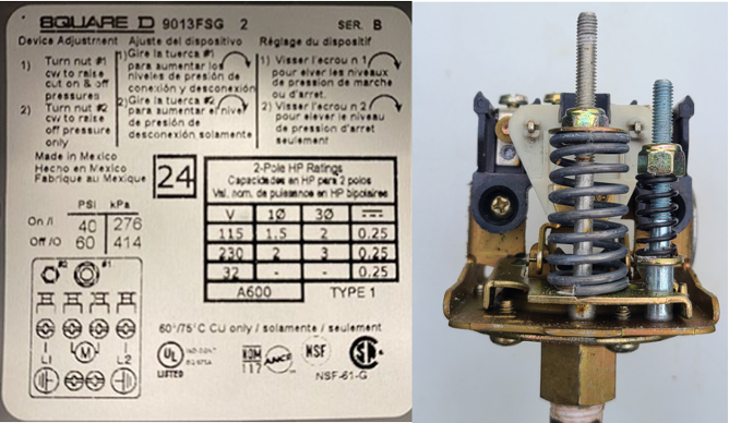
- Loosen the nut on top to remove the cover on your pressure switch. Notice there is wealth of information given under the cover of the pressure switch including the factory pre-sets (Figure 75). You will notice two springs. The range adjustment nut on the larger center spring controls both the cut-in and cut-out settings together. The smaller spring controls only the highest pressure in the range (cut-out). This is a less commonly used part of the pressure switch, and you’ll only want to adjust this one if you have a very specific reason to do so.
Remember that the 20 psi differential range is part of the overall system design that limits the amount of pump cycles in a day. If the range gets reduced to lass than 20 psi it will shorten the pump run time and reduce the pump life. - To adjust the switch use a [latex]\tfrac{3}{8}[/latex]” deep socket nut driver. Rotate the center spring range nut in a clockwise direction for higher cut-in pressure and counter clockwise for lower cut-in pressure. As you start to change the cut-in value, the cut-out value will change by the same amount and in the same direction. The rule of thumb is that one full rotation will adjust the pressure 2-3 psi.
- After making the adjustment you will need to monitor the system to ensure the pressure setting is what you desired. Note that the adjustment you make to the pressure switch can only be read after the pump has reached its first adjusted shut off. The next cut-in and cut-off pressure is your new setting.
- Replace the cover onto the switch, turn the power back on
- Open the drain to get the pressure below the cut-in point. Once the pump turns on close the drain. Keep a close eye on the pressure gauge so that you can identify the exact point that the pump turns off.
- Repeat adjustments if necessary and continue monitoring for a couple more cycles
As mentioned there are very few applications where you should use the small spring to adjust the differential. Adjusting the differential will only adjust the cut-off pressure. Turn the differential nut counter clockwise to lower cut-off pressure or turn the nut clockwise to raise cut-off pressure.
Protective Devices
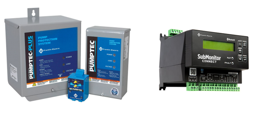
For pump protection, additional devices can be installed that monitor motor load and incoming power conditions to provide protection against dry well conditions, waterlogged tanks, and abnormal line voltage conditions. These devices interrupt power to the motor whenever the load drops quickly or below a pre-set level. Some devices can also be connected to the a mobile App to provide real-time system monitoring.
In Figure 76 the devices shown on the left are designed for single-phase motors. Whereas the device shown on the right is for protection of three-phase motors.
Troubleshooting Pump Problems
When trying to solve a problem with a pumping system the causes can seem endless, but fact-finding and observation go hand in hand with resolution of the problem. When you encounter a problem with the operation of a pump or some part of the pumping system, always look for the most obvious causes and try the straightforward solution. Work progressively from easy solutions to the more difficult ones. Always weigh the relative costs in time and materials when deciding whether to repair or replace defective components.
These troubleshooting charts [PDF] look at common problems encountered with different types of pumps and systems. The problem is listed first, followed by a series of checking procedures.
 Now complete Self-Test 5 and check your answers.
Self-Test 5
Self-Test 5
Media Attribution
- Figure 69. "Ammeter test" ©SkilledTradesBC Province of British Columbia. These resources are not designed for rework, reuse, remixing, and/or redistribution; they are to be used solely for the purposes of instruction.
- Figure 70. "Submersible pump insulation resistance test" from Franklin Electric is used for educational purposes under the basis of fair dealing.
- Figure 72. "Motor winding test" from Franklin Electric is used for educational purposes under the basis of fair dealing.
- Figure 73. "Control box connections and label" by Camosun College is licensed under a CC BY-NC-SA licence.
- Figure 74. "Cable leakage test" ©SkilledTradesBC Province of British Columbia. These resources are not designed for rework, reuse, remixing, and/or redistribution; they are to be used solely for the purposes of instruction.
- Figure 75. "Pressure switch cover removed" by Camosun College is licensed under a CC BY-NC-SA licence.
- Figure 76. "Pump no load protection devices" from Franklin Electric is used for educational purposes under the basis of fair dealing.

