Competency C1: Install Rural Water Supply Systems
Learning Task 4
Describe the Testing and Commissioning of Water Supply Pressure Systems
The proper testing and commissioning of pumped rural water supply systems serving single-family dwellings is of utmost importance in ensuring the well-being, and quality of life for individual households. Detecting and rectifying potential issues during the testing phase, such as leakages, pressure irregularities, or water contamination, ensures that the system operates efficiently, saving the homeowners from unexpected repair expenses and water wastage.
Moreover, commissioning a pumped water supply system for a single-family dwelling optimizes its performance and reliability. Proper integration with the household’s plumbing ensures a steady flow of water, providing convenience and meeting daily needs.
If the well water was not analysed when the well was developed this should be done immediately, before connecting to the house plumbing, to determine if any special water treatment equipment is required.
After electrical work is completed and before pump is connected to pressure tank, the pump should be primed and test run.
Jet Pump Initial Start and Performance Check
For a centrifugal pump to function effectively, it must undergo a priming process. Priming involves filling the suction line with water and maintaining it at capacity while the pump operates. This step is particularly crucial for suction pumps, as it requires patience, time, and a substantial amount of water to ensure the suction line is completely full and the pump case has enough water to generate suction. Submersible pumps generally do not require priming when placed in a well since they are positioned below the well’s static water level, ensuring a positive suction head to start efficiently.
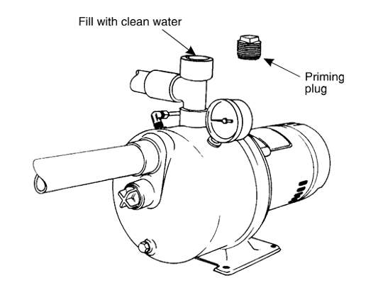
A discharge tee and priming plug may need to be installed onto the pump if it was not supplied with one (Figure 68). Install temporary piping or hose with a shutoff valve onto the branch outlet of the discharge tee. Route the temporary piping or hose to a drain to enable the pump to be run for a period of time to ensure all of the air has been removed.

To successful prime and test run the pump several important steps must be taken:
- The entire line from the pump location to the foot valve in the well must be fully filled with water to eliminate any air from the suction line.
- Filling the entire suction line and pump case through the top of the priming tee requires multiple cycles of closing the priming opening and starting the pump to ensure a sufficient water level.
- A quicker way to prime the pump’s suction line is to fill it entirely before connecting it to the pump. By observing the water level in the suction pipe before the connection, you can ensure the foot valve holds water, speeding up the priming process as only the pump case needs to be filled with water, possibly venting some air from the suction line.
- Priming is greatly assisted by having the suction line rise slightly (graded) from the pitless adapter or wellhead to the pump’s inlet.
- When priming a two-pipe jet pump installation, make sure to fill both lines before connection to the pump.
- Confirm that the pressure gauge and pressure switch sensing line are connected.
- Close the temporary discharge shutoff valve and start the pump. If pump is installed with a horizontal offset line of 4 feet or more, it may take several minutes to prime. Opening the discharge valve slightly the may help removed air from the pump casing. If pump pressure does not build up in 5 minutes stop the motor, remove the priming plug, add more water and repeat.
- For a deep well jet turn regulator adjusting screw down tight. If pump is properly primed, a high pressure will immediately show on pressure gauge. With pump operating at high pressure, slowly unscrew regulator adjusting screw until maximum water flow is obtained without pressure dropping to zero. If pressure does drop completely, again tighten down regulator adjusting screw and readjust until steady operation is obtained
- Allow pump to run to drain long enough to clear the well of any sand or dirt and to be sure the well is not going to run out of water.
Stop pump and complete connections to pressure tank. Allow the pump to cycle automatically several times to check pressure switch setting and operation.
Submersible Pump Initial Start and Performance Check
To ensure system performance the following steps must be taken at initial start up of a submersible pump before making the final connection to the discharge system.
Startup Procedures
- Install a pressure gauge and valve on the end of the discharge pipe.
- Route the temporary piping or hose to a drain to enable the pump to be run for a period of time.
- Discharge valve must be closed to approximately 1/3 open when the pump is started to slow the air released from the drop pipe, in tum causing backpressure on the pump as the air becomes slightly compressed before escaping from the valve.
Notice:
Never start a new pump installation with the discharge valve completely open. When a submersible pump operates at high flow – low head, it can cause the pump to up thrust the impellers-shaft assembly, which can cause premature wear and failure. - Once the air has escaped, open the valve gradually until the pump operates at its full capacity. Avoid turning off the pump even if it experiences water deprivation during well cleaning or development. Shutting down the pump under such circumstances could lead to clogging due to the accumulation of tiny solid particles, making it difficult to restart when needed. However, if the pump continues running while water re-enters, there is a higher likelihood of successfully pumping these particles through the pump stages.
- As the valve is being opened, the drawdown should be checked to ensure that the pump always remains submerged. Continue to run the pump until the drawdown of the water in the well becomes stable. Should the water level drop to the pump intake the installation of a protection device against dry operation is recommended.
- Continue to run until the water that is flowing out of the temporary discharge pipe is clear.
Caution the piping has not been connected to the tank and pressure switch yet, therefore the pump pressure could continue to rise above the system setpoint and beyond possibly damaging the supply piping and or fittings. Watch the pressure gauge carefully during this stage and be prepared to shutoff the pump if the pressure gets over 550 kpa (80 psig).
Pump Performance Checks
Check the pump and well performance before making the final connection to the discharge system.
Close the valve and start the pump, check the pressure developed against the closed valve. If the pump has a three-phase motor and the pressure is substantially less than expected, the pump may be running backward. To change the rotation of a three-phase motor, interchange any two leads, then. run the motor again at shut-off, measuring discharge pressure. The cable arrangement that produced the highest discharge pressure is the correct one to ensure proper rotation.
The pump must not operate above the motor nameplate maximum amps. With the pump running open the gate valve gradually until full flow is achieved. Use a clamp-on amp meter to read the current, which should approximate the full-load current given on the motor nameplate, but must not exceed the service factor rating of the motor. Record the running current for future reference.
For three-phase motors, after the correct rotation has been established, check the current imbalance. The procedure for checking three-phase motor current imbalance is explained in Learning Task 5
Use a voltmeter to verify the voltage at the starter while the pump is running. The voltage must be within 10% of the motor rating, and the maximum variation of any phase of a three-phase system from the average should not exceed 1%.
The most reliable indications of the condition of a submersible pump are the current drawn by the motor and the insulation resistance of the installation below ground. Check and record the insulation resistance for future reference.
The procedure for checking insulation resistance is explained in Learning Task 5.
Completed System Checks
Once the initial pump start-up and performance check have been completed then the piping connection can be completed to the pressure tank and household. The final system checks can now be performed.
Energize the pump and monitor the pressure gauge to confirm the pressure switch cut-off setting. If the pressure continues to build up past the cut-off setting, shut off the pump and trouble shoot the pressure switch.
Once the pump has shut-off open a large demand faucet or hose bib and allow the pump to cycle automatically several times to check pressure switch setting and operation. If the pressure cut-in or cut-out setting are not correct then the pressure switch will need be to be checked out and possibly adjusted. Observe and record the amount of pump run time for each cycle. If the run time is longer or shorter than the expected then you will need to trouble shoot the pump or pressure tank.
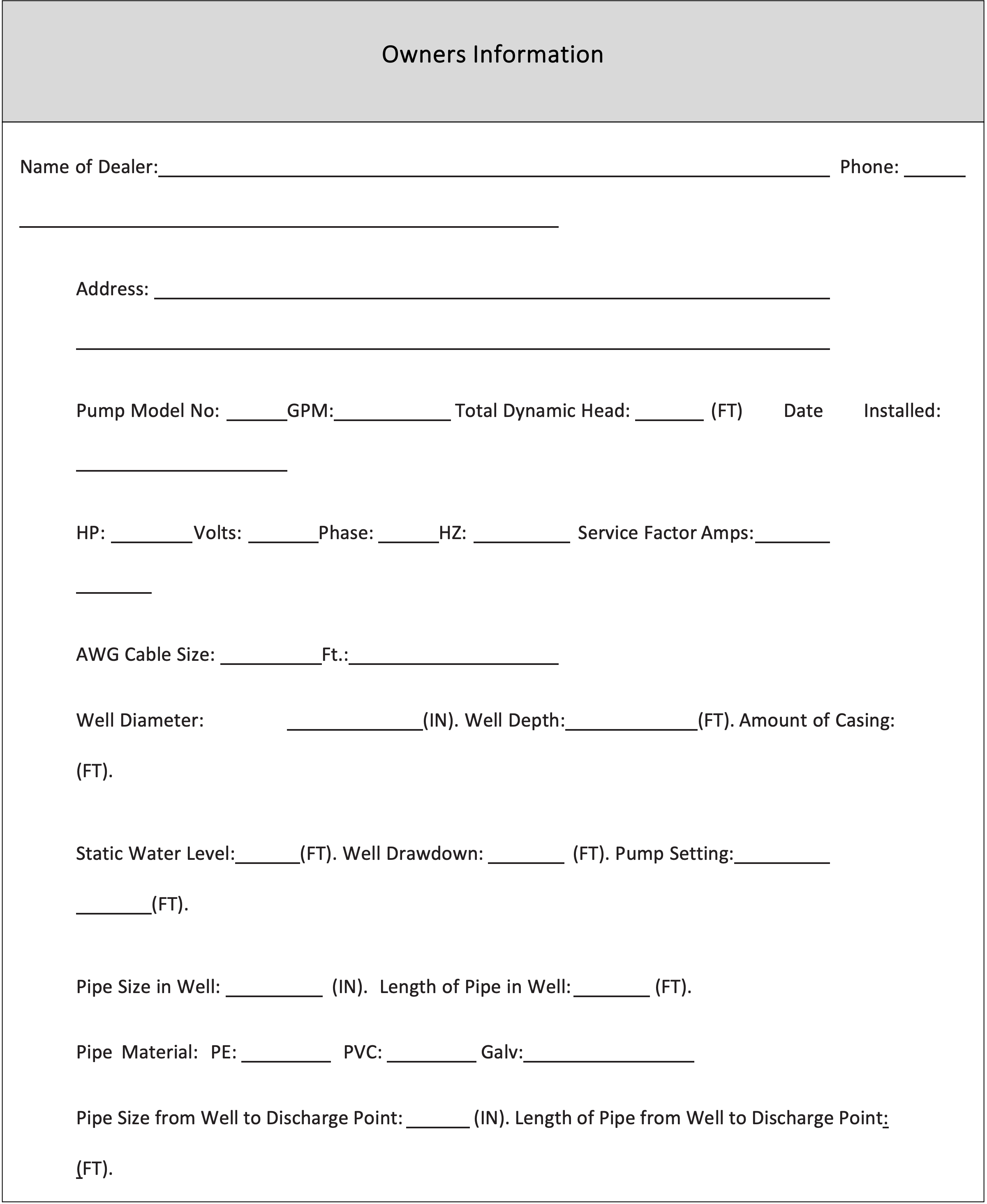
Once the installation system has checked out, all of the system information must be recorded and given to the owner. An example of an owner’s information form is shown below:

 Now complete Self-Test 4 and check your answers.
Self-Test 4
Self-Test 4
Media Attributions
- Figure 68. “Shallow well pump with discharge tee” from Grundfos is used for educational purposes under the basis of fair dealing.

