Competency D1: Install Sewage Treatment Systems and Components
Learning Task 1
Describe Private Sewage Disposal Systems
The handling of human waste has evolved from depositing it on the ground, where it would decompose naturally and be inoffensive due to the absence of population density, to sending it through piping systems to a municipal plant for proper treatment and disposal. History has proven that many of the plagues and diseases that have followed humankind’s quest to develop urban areas have been associated with our inability to properly treat and dispose of human waste. This section will concentrate of the description of current sewage treatment systems for residential use in rural areas, with a focus on requirements specific to British Columbia.
Learning Objectives
After completing this learning task, you will be able to:
- Describe the purpose and operation of a residential Type 1 sewage treatment system
- Identify the components found in a residential Type 1 sewage treatment system
- Describe factors affecting the installation of sewage treatment systems
Key Terms
- AP: authorized person
- ASTTBC: Applied Science Technologists and Technicians of British Columbia
- ROWP: registered onsite wastewater practitioner
- SSR: Sewerage System Regulation within the Public Health Act
- SPM: Sewerage System Standard Practice Manual, Version 3
- BOD or BOD5: 5-day biochemical oxygen demand
- TSS: total suspended solids
There will be other definitions encountered within the text, and the initialisms for them will be provided and used thereafter for brevity.
What is a Private Sewage Disposal System?
A sewage treatment system (also referred to within the context of this learning guide as a “sewage disposal system,” “septic system,” or “sewerage system”) is the system of pipes, pumps, tanks, and other equipment used for the collection, transport, and disposal of residential wastewater (sewage).
The BC Sewerage System Regulation (SSR) defines a sewerage system as “a system for treating domestic sewage that uses one or more treatment methods and a discharge area but does not include a holding tank or a privy.”
A holding tank is defined by BC Interior Health as “a large container that is used to collect and temporarily store sewage from a home or building. The sewage is removed and transported to an approved location for disposal.” Holding tanks are large cement or plastic tanks into which household wastewater flows and is stored until it is pumped out. These tanks are used in place of a septic system due to factors such as:
- restrictive soil conditions and percolation rates
- insufficient field area
- proximity to property boundaries, water tables and wells
According to the BC Sewage Disposal Regulation, a privy means “a small building having a bench with a hole or holes through which human excretion may be evacuated into a waterproof vault or into an excavated pit.” Simply stated, it’s an outhouse.
As defined by the SSR, a sewerage system has two components:
- one or more treatment method(s)
- a discharge area
Both components of the sewerage system play a role in treating the sewage but are addressed in different ways in the SSR and therefore, in this learning guide.
The Sewerage System Regulation (SSR) and Sewerage System Standard Practice Manual, Version 3 (SPM) [PDF] are both available online to download at no cost to the user. You are encouraged to access these publications if you wish to have a more detailed description of the summary information presented in this learning guide.
Who Can Install Septic Systems?
Prior to June 1, 2005, a proposed septic system required a permit which could be obtained from a local BC Health Unit. The permit package went so far as to also include sizing criteria and on-site design parameters for concrete septic tanks and disposal fields; in other words, the “whole how-to.” The permit holder was typically the homeowner, who could choose to do all, some, or none of the work themselves. Plumbers or contractors with a backhoe and dump truck were most often the homeowners’ choice for carrying out the installation, and they needed no prior experience or training to do this work. After the system was installed, but before it was backfilled, an inspection by a representative from the local health authority (health inspector) was required. Once the installation was acceptable to the inspector, who also logged and archived the associated paperwork with the Ministry of Health, the system was backfilled, put into operation, and subsequently ignored or forgotten until such time that a problem arose.
Since the stroke of midnight May 31, 2005, installations in British Columbia have fallen under the jurisdiction of the Sewerage System Regulation (SSR) which was legally adopted under the Public Health Act. The regulation sets out rules for the planning, installation, and maintenance of onsite sewage systems. Collaboration between BC’s Ministry of Health, the Applied Science Technologist and Technicians of BC (ASTTBC), independent contractors and industry stakeholders resulted in the development of the Sewerage System Standard Practice Manual, Version 3 (SPM), which is considered by most to be the “code” for septic systems in British Columbia. Within the SSR and SPM, only an authorized person (AP) is allowed to plan, install, and maintain onsite wastewater treatment systems, and they must also file the necessary documentation with the Ministry of Health within 30 days from completion of the installation. As well, the owner of the system must designate an AP to provide the required maintenance of the system.
According to the SSR and SPM, an AP means either a registered onsite wastewater practitioner (ROWP) or a professional. Sections 7 (1), (2), and (3) of the SSR spell out in detail the training and background requirements that ROWPs and professionals must meet. The summaries of these sections are:
- an ROWP is certified by the ASSTBC, usually by taking requisite courses of training delivered by accredited trainers
- a professional typically means an engineer accredited by APEGBC (Association of Professional Engineers and Geoscientists of BC)
Further to this, there are three designations of ROWP:
- Planner, responsible for site and soil evaluation and planning of systems
- Installer, responsible for installation of systems
- Maintenance Provider, responsible for maintenance of systems
A fourth designation that is accredited by the ASTTBC, but not addressed in the SSR or SPM is:
- Private Inspector (PI), responsible for the assessment of existing systems, typically to support real estate transactions or building permit applications.
This endorsement is split into two categories:
- Private Inspector Residential (PIR), and
- Private Inspector Commercial (PIC)
Section 6 (1) of the SSR does have an exception wherein a homeowner can do the work of installing a Type 1 or 2 system, but only if being supervised by an AP.
Purpose of the SSR
The primary purpose of the “new” regulations was to protect the public interests by treating sewage to an acceptable level of quality by the time it reaches the “limiting layer” (an aquifer or bedrock). The standards developed for the SPM are based on the effluent being treated to, at minimum, “recreational water quality” at the limiting layer. This is meant to be water that is not considered potable but could be used for swimming or bathing. Secondary to that was the goal to have an installation that, with proper attention paid to maintenance should operate as intended for a minimum of 35 years1. As well, the legislation took the onus of the certification and acceptance of properly installed systems from the shoulders of the local Authority Having Jurisdiction (i.e., the local Ministry of Health officer) and set it squarely upon the shoulders of the AP. Health inspectors no longer visit installation sites unless requested or if problems are encountered.
Bacteria at Work
Sewage is broken down and rendered harmless because of the actions of certain bacteria present within the system. These are anaerobic and aerobic bacteria, and they are associated with the primary and secondary treatment areas of a Type 1 system.
Anaerobic Bacteria
Anaerobic bacteria are present in the septic tank. They operate in environments where it is moist, dark and there is little or no oxygen. They are smaller and less efficient in breaking down the waste than aerobic bacteria, but they are more resilient and can withstand larger changes in their environment. They help in the partial decomposition of the solids and sludge within the tank. The sludge layer is made up of both biodegradable and non-biodegradable solids and so the anaerobic bacteria cannot completely break it down. For this reason, septic tanks must be sized to allow an accumulation of sludge before being pumped at intervals as stipulated by the SPM and SSR (covered later in this learning guide). The bacterial digestion in a septic tank, called “septicization” or “putrefaction,” is an anaerobic process.
Aerobic Bacteria
Because there is little to no free oxygen within the tank of a Type 1 system, aerobic bacteria that work best to break down sewage can’t survive there. They do, however, thrive in the dispersal field, where the oxygen content in porous soils of properly constructed systems allow these bacteria to complete the process of rendering the effluent harmless by the time it reaches the limiting layer of bedrock or an aquifer. The process whereby aerobic bacteria break down effluent is called “oxidation.”
Treatment Methods
The treatment method is the treatment system that precedes the dispersal area. Typically, this consists of a septic tank (Type 1) or a package treatment plant (Type 2 or 3), and is defined in the SSR as:
- Type 1: Treatment by a septic tank and dispersal field only.
- Type 2: Treatment that produces an effluent consistently containing less than 45 mg/L of TSS and having a BOD5 of less than 45 mg/L.
- Type 3: Treatment that produces an effluent consistently containing less than 10 mg/L of TSS and having:
- A BOD5 of less than 10 mg/L.
- A median fecal coliform density of less than 400 Colony Forming Units per 100 mL.
Prior to the implementation of the SSR and SPM, there were no quantifying terms used to indicate the strength of sewage. Today, sewage strength is indicated by the term BOD or BOD5, which stands for “5-day biochemical oxygen demand.” This is the standard for referencing sewage strength and represents the total amount of oxygen, in mg/L, used by microorganisms in decomposing one litre of organic matter in a 5-day period. A higher BOD number means more oxygen is required and indicates water of a lower quality. The lower the BOD, the higher the water quality.
The term “median fecal coliform density,” used above in defining Type 3 treatment methods, is another basic chemistry yardstick for determining the biological quality in a water supply, and its explanation or description is unnecessary for the purpose of this learning guide, as we will primarily concentrate on Type 1 systems.
As well, the scope of the SSR covers:
- Systems that process sewage flow of less than 22700 litres (4989 imperial gallons) per day
- Single-family dwellings or duplexes
- A combination of sewage systems that addresses different buildings on a single parcel of land
- Structures that serve one or more parcels on strata lots or on a shared interest of land.
The SPM standards are intended to be simple and easy to apply. In general, standards are focused on providing simplest, lowest cost solutions first, which are considered to be Type 1 treatment methods discharging to:
- Gravity distribution systems
- Pressure distribution systems, and
- BC zero discharge lagoons, evapotranspiration (ET) beds and evapotranspiration absorption (ETA) beds (all are limited to application in certain parts of the province)
Small flow, residential systems are considered the main priority of the SPM. The SPM standards are focused on the majority of systems and sites, and do not prioritize the “what if” or “one of” situations that may arise. Larger wastewater systems are addressed by the Ministry of Environment and Climate Change Strategy through the Municipal Wastewater Regulation under the Environmental Management Act and will be covered later in this learning guide.
Dispersal Area
Dispersal areas are defined in the SSR as “areas used to receive effluent discharged from a treatment method.” They are responsible for treatment for the wastewater as it travels through the soil column to the base of the vertical separation, known as the “limiting layer,” considered to be either an aquifer or layer of bedrock. The standards of the SPM were developed in recognition of soil-based treatment and aim to achieve the recreational water quality objectives at the base of the vertical separation, while accounting for the long-term acceptance rates of the soil. It is because of these factors the SPM provides differing dispersal area standards for different treatment methods, soil types, and dispersal methods. The SPM refers to the following five methods of distributing Type 1 effluent to the dispersal area:
- Gravity distribution, either:
- Trickle gravity, or
- Dosed gravity
- Uniform distribution, meaning either:
- Pressure distribution
- Subsurface Drip Dispersal (SDD), or
- Alternate methods of uniform distribution, provided that they meet the standards set out in the SPM
Choosing an appropriate dispersal method is a complex undertaking and must take into account many factors such as sewage strength, useable land area, installation cost, and equipment availability, but in all likelihood the most difficult factor to deal with is a soil analysis. Therefore, this learning guide will focus on providing broad explanations behind these factors without delving too deeply into their detailed aspects. In-depth study of these factors for certification purposes is the intent of the various courses of training for becoming an AP. Those wishing to explore that route should access the BCOSSA (BC Onsite Sewerage Association) website.
Self-Test 1
Self-Test 1
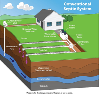
Type 1 Septic Systems
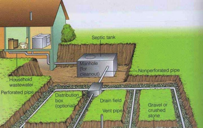
A conventional Type 1 septic system consists of a septic tank, distribution box, and dispersal field. This has long been the standard system in use for rural residential settings. We’ll look at each of the three components separately.
The Septic Tank
Septic tanks are the primary treatment component of a Type 1 sewage treatment system. Septic tanks can be rectangular or round and are constructed of steel (for temporary use), reinforced concrete or plastic, with concrete being the material of choice due to its robust design and longevity. Most concrete tanks will likely outlast the house if properly constructed and installed. All septic tanks must conform to CAN/CSA-B66-00 “Prefabricated Septic Tanks and Sewage Holding Tanks,” as set out by the Canadian Standards Association.
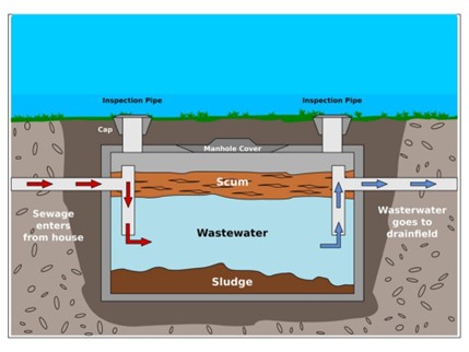
Raw sewage from the house sanitary building sewer enters the tank through the inlet baffle. The baffle can either be built into the tank’s inner wall or can simply be a sanitary “T” fitting with the lower outlet extending vertically downward for a short distance. The inlet baffle’s job is to provide “quiescent” flow. This is described as slow-moving flow that doesn’t promote the movement of eddies or liquid currents which could carry solids across the tank toward the compartment’s outlet. The quiescent flow allows the raw sewage to separate into three “layers”:
- Solids, including seeds, peels and other hard-to-digest particles that settle to the tank bottom to form a layer known as “sludge.” Sludge is meant to accumulate and be stored in the tank until pumped out.
- Fats, soaps and oils float on the surface of the liquid to form a layer known as “scum.” Scum forms an insulating barrier above the effluent and, like the sludge, is meant to not leave the tank until being pumped out.
- The wastewater (“effluent”) layer between the scum and sludge leaves the tank through gravity piping or pumping and is directed into the dispersal system.
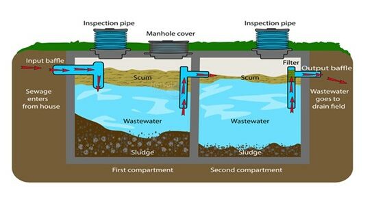
An outlet baffle, usually a tee, is specified by the SPM at the outlet of each compartment. The lower vertical pipe of the tee extends down into the clearest effluent, preventing floating matter and solids from leaving the compartment. It extends far enough to allow an accumulation of sludge over the intended time between pump-outs. The baffle at the outlet of the final compartment (before the effluent flows to the dispersal system) is fitted with a filter that prevents larger undigested particles from leaving the primary treatment device and passing into the secondary treatment area.
Depending on the sizing requirements and dispersal method used, there may be a second compartment or second tank in a Type 1 system. Two tanks allow for better separation of sludge and scum but if sized correctly, a single tank may be used.
A second compartment or “dosing” tank can also be found in systems where dosing is desired. Dosing is the term given to the process of flooding the disposal field with a high flow rate discharge. Either a siphon or a pump is used to quickly evacuate the dosing tank and utilize the entire dispersal system, rather than just the first few metres of it that a “trickle” system would employ. In a trickle system, effluent leaves the tank at the same rate that raw sewage enters. Most Type 1 systems are of the trickle variety.


Package Sewage Treatment Plants
Package sewage treatment plants, also known as aerobic treatment units (ATUs), use many of the same processes as a municipal sewage plant, but on a smaller scale. An aerobic system injects oxygen into the treatment tank through an air pump. The additional oxygen increases natural bacterial activity within the system that then provides additional treatment for nutrients in the effluent, normally taking it to a Type 2 level. Some aerobic systems may also have a pre-treatment (“trash”) tank and a final treatment tank including disinfection to further reduce pathogen levels.
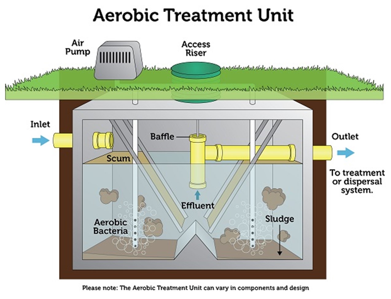
The benefits of these systems, categorized as Type 2, are that they can be used in homes with smaller lots, inadequate soil conditions, in areas where the water table is too high, or for homes close to a surface water body sensitive to contamination by pathogens contained in wastewater effluent. The disadvantages are that they require power and routine monitored maintenance and are more costly to initially install and thereafter maintain.
The Distribution Box
The purpose of a distribution box is to spread the flow from the tank equally to all the laterals (single perforated pipes) in a dispersal field of a Type 1 gravity distribution system. They are used with either a trickle or dosed discharge.
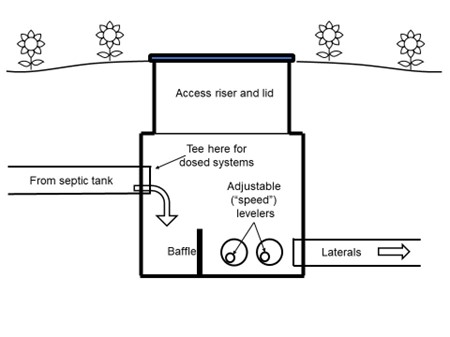
Distribution boxes (“D-boxes”) are constructed of either concrete or plastic. Concrete D-boxes have one pipe inlet and multiple pipe outlets, normally of 4-inch diameter, cast into them. A baffle near the inlet helps to ensure “quiescent” flow between the inlet and outlets. D-boxes should be installed as level as possible so that the invert of each outlet is at the same elevation. To compensate for any out-of-level condition, adjustable eccentric levelers, known as “speed levelers,” are fitted into the outlet openings and are rotated so that the inverts of the openings are all at the same elevation. An access riser, fitted with a sealed lid, ensures the distribution box’s operation can be easily checked and maintained without excavating.
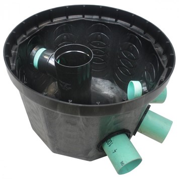
Plastic D-boxes have multiple knockout openings at different elevations, for more control over installation. A plastic pipe is inserted into a rubber grommet in the opening, allowing for a watertight seal between the pipe and D-box. Speed levelers and access risers can also be fitted to the openings of plastic D-boxes.
The Dispersal Dystem
Dispersal systems are the secondary treatment component of a Type 1 system. In it, aerobic bacteria break down the effluent into a final quality of discharge that will not harm people or the environment. There are several dispersal systems available for consideration, and the criteria for their selection are exhaustive and complex. Therefore, we will limit our studies to providing descriptions and characteristics of the different types, rather than attempting to go into detail with selection or sizing of any particular dispersal system.
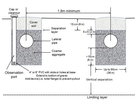
Trench Systems
The most widely-used type of dispersal for a Type 1 system uses horizontal trenches of 18–36 inches in width at the bottom that are dug into native soil. Effluent from a distribution box spill into laterals of perforated pipe that are surrounded by gravel (commonly known as drain rock) and percolate vertically and laterally through the vertical separation. The gravel layer over the lateral is covered with an infiltrative cloth, called a separation layer, and native cover soil is replaced on top of it. The cover soil is left mounded to allow for settlement and to thwart groundwater from infiltrating the trench, which could saturate the soil and affect its ability to operate as intended. An observation port allows checking of the trench for issues such as ground saturation, seasonal water table depth, etc.
Gravity Distribution: Trickling Systems
These are the most common systems used. When raw sewage enters the septic tank, it displaces effluent which moves out of the tank to the distribution box and out into the field piping. Low flows, such as from a basin or sink, only discharge enough liquid per use to affect the first few feet or meters of field distribution piping, leaving the rest of the field largely unused. Higher flows, such as from a bathtub or washing machine pump out cycle, will move farther into the distribution system. For this reason, trickling systems more commonly suffer from plugging of the first few feet or metres of laterals.
Gravity Distribution: Dosed Systems
When a high flow of effluent is released from the tank to fill the field piping, it is known as “dosing.” Dosing a field has a few advantages over trickling, including:
- The entire field gets a workout, rather than just the first few metres of it
- The field is allowed to “breathe” (rest) between doses, promoting aerobic bacterial action
- Freeze up of the field is less likely to occur in cold climates
Dosing can be accomplished by using either a siphon or a pump.
Dosing using a siphon has the advantage of not needing a power supply. When the effluent in the siphon chamber reaches a specific depth, the siphon trips and draws the contents of the chamber through the trap and, by gravity, out to the field.
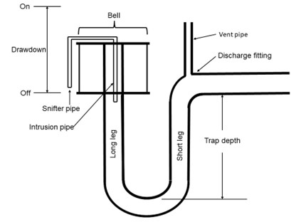
In installations where there is not enough room for a single disposal field, two separate smaller fields can be serviced by installing two siphons in a single dosing tank. Because of slight variations in dimension and/or slight variations in the elevation of the two bells (inverted domes over the siphon inlet), one of the two siphons will trigger first. The siphon that triggered first will end the first dosing cycle with its trap full. The siphon that didn’t trigger will have lost much of the water in its trap at the end of the first dosing cycle. When the tank fills up a second time, the second siphon will trip first since its trap is only partially full and requires less pressure to trip. The third time the tank fills up, the first siphon, with its trap only partially full, will trip first. This alternating process will repeat itself indefinitely.
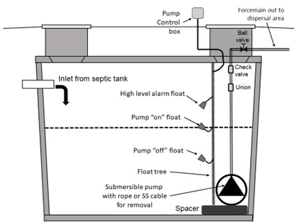
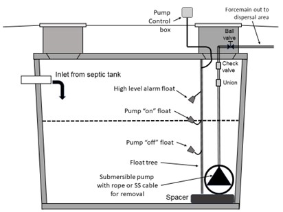
Dosing using a pump is fairly straightforward. A submersible pump installed in either a tank’s second compartment or a separate tank sends effluent out to a distribution box or to a pipe manifold and into the field piping. A simple float switch can be used to turn the pump on and off, or a more elaborate system using multiple float switches or sensors can be connected to a pump control panel. Regardless of the control system chosen, a high-water alarm should be used so that the owner can be alerted to potential issues before they become problematic.
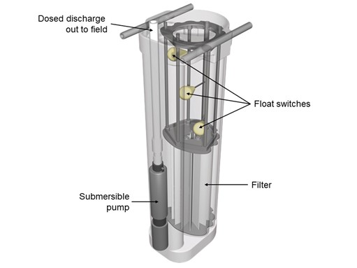
A tank vault, sometimes known as a hanging pump vault, is a self-contained, manufactured package that encloses the dosing pump, screen, filter and float controls, and is installed near the tank outlet. The vault allows for easier installation and maintenance of the pump, filter, and controls.
Dosing, either timed or on demand, occurs in all pressurized systems, whether above or below grade.
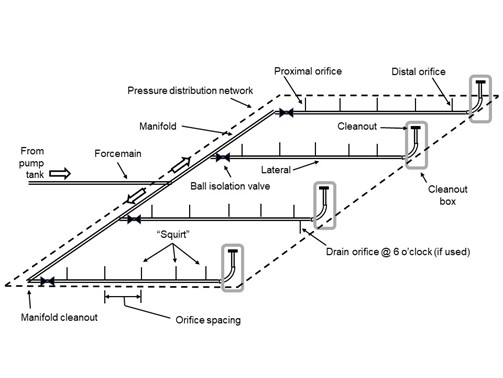
Pressure Distribution
With the subdivision of large land parcels into smaller rural lots came the need to be able to operate septic systems that occupy a smaller footprint. This has resulted in the development of pressurized dispersal systems known as:
- Pressure distribution, and
- Subsurface drip dispersal
Pressure distribution systems use a pump to send effluent out through small-diameter pipes with orifices drilled in them in a symmetrical pattern to discharge effluent evenly to the infiltration surface. The pump and pump chamber are similar or identical in design to ones that supply dosing to a gravity distribution system, except that the required pump heads will differ. Pressure distribution results in a more uniform application rate through the dispersal area, with no more than a 15% variation between any two orifices in a properly designed system.
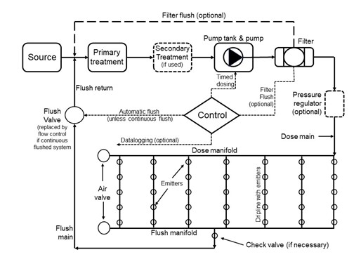
Subsurface Drip Dispersal (SDD) Systems
Subsurface drip dispersal (“SDD”) systems use timed dosing of filtered effluent to specially designed small diameter drip tubing, installed in soil close to the ground surface. A fine pressure filter, sized for the system flow and emitter size requirements, is used downstream of the dosing pump. Emitters in the tubing dose the effluent at a low hydraulic application rate to the soil.
Alternate Dispersal Methods
While trench-type disposal fields remain the norm for rural sewage dispersal, various factors may require the use of an alternate system, such as:
- Gravelless “Infiltrator®” systems
- At Grade and raised systems
- Seepage bed systems
- Sand mounds and sand-lined trenches
- Evapotranspiration (ET) and evapotranspiration absorption (ETA) beds
- Lagoons
- Combined treatment and dispersal (CTDS)
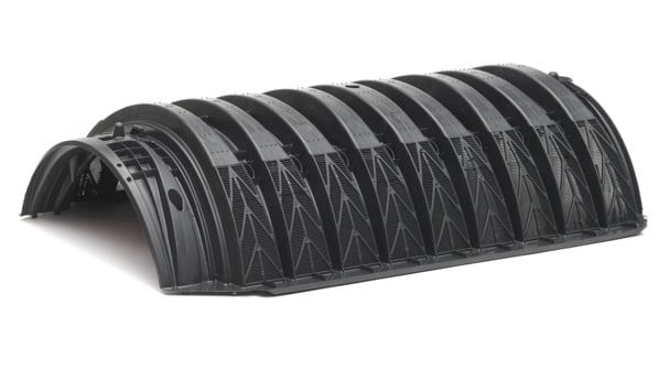
Gravelless “Infiltrator®” System
Infiltrator® systems were developed in the mid-1980s as an alternative to the decades-old concept of gravel-and-pipe leaching beds. A series of pre-manufactured plastic chambers are connected end-to-end in a level trench wide enough to accommodate them. The effluent enters the chamber through a built-in pipe channel near the top and spills downward through weepholes into the trench bed. Infiltrator® systems have advantages over gravel-and-pipe leaching beds in that they are strong enough to support minor traffic loads caused by farm equipment, need no gravel base, and have a large infiltrative area.
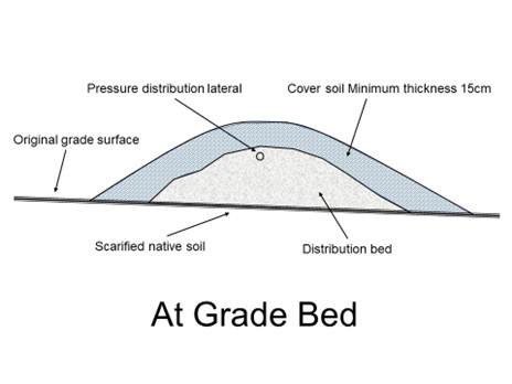
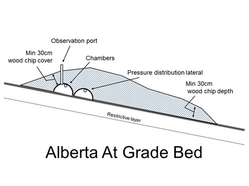
At Grade Beds and Raised Systems
In cases where the native soil is too impermeable for percolation of effluent, At Grade and raised systems may be used. The SPM references an At Grade bed as an aggregate bed placed on prepared topsoil of a site, into which effluent is distributed by pressure. This could be Type 1 effluent, whereas an Alberta At Grade system is a gravel-less chamber system (i.e., Infiltrator®) placed on undisturbed native topsoil into which Type 2 or Type 3 effluent is distributed by pressure. Both are restricted in their use to certain sites and soil types.
Seepage Bed Systems
A seepage bed system is simply a wide infiltration trench (> 90 cm), containing more than one distribution lateral. Seepage beds have less oxygen transfer than trenches due to reduced sidewall area and therefore are limited by the SPM to a maximum width of 3 m. Laterals can be placed fairly close to one another and thus they take up less space than trenches using the same number of laterals. Seepage beds are not allowed where the land slope in the dispersal area is more than 15% and are only allowable for use in more permeable soil types.
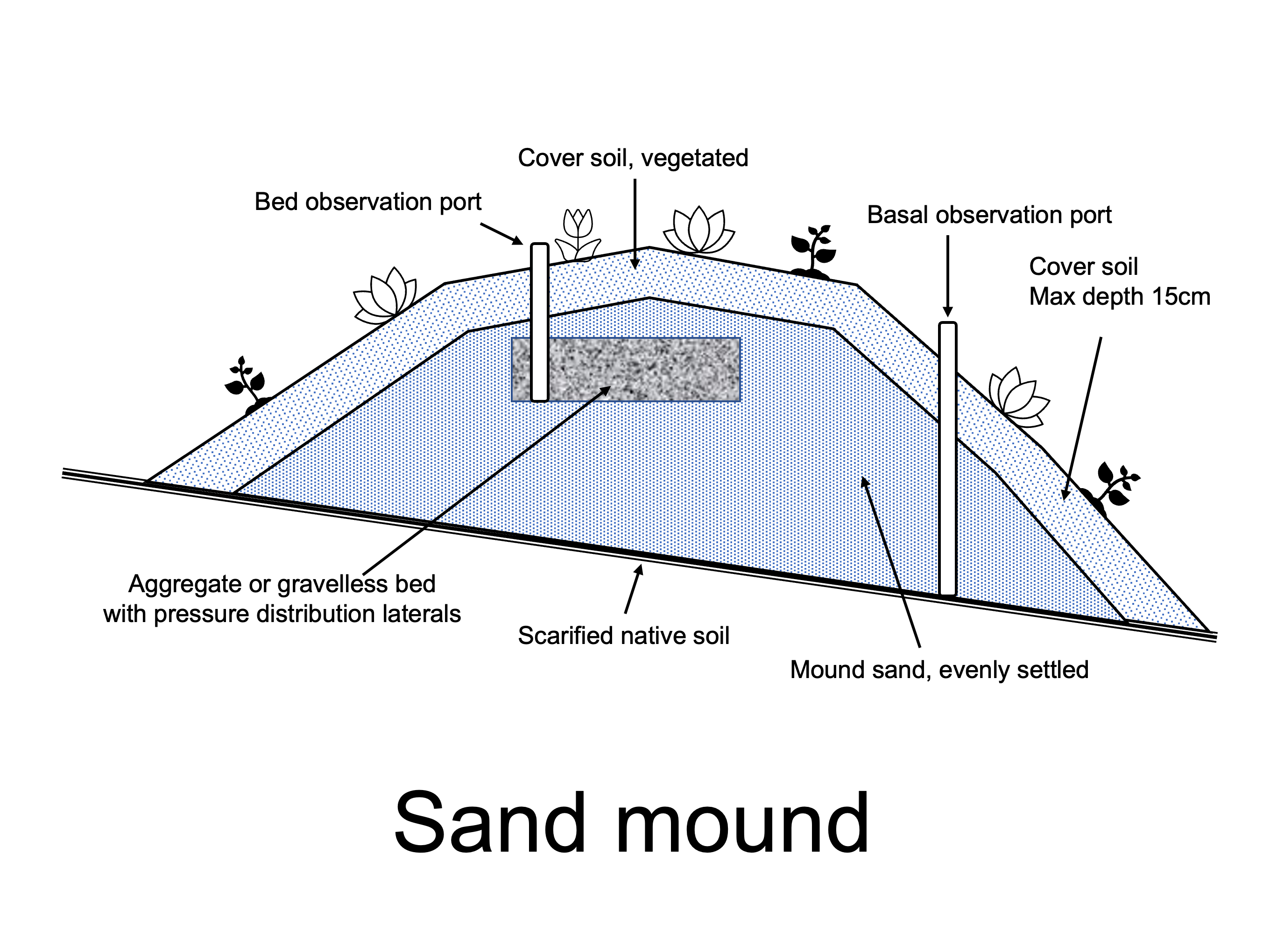
Sand Mounds and Sand-Lined Trenches and Beds
Sand mounds, and sand-lined trenches and beds, are sand-based dispersal systems where the effluent is dispersed to a bed on the sand, using pressure distribution or subsurface drip dispersal and timed dosing. The bed is level and installed long and narrow on contour, with a bed length selected to meet a specified linear loading rate (LLR). A sand mound is installed with the bed above grade on minimum 30 cm of sand media fill. Sand lined trenches and beds are installed with the bed at or below grade on minimum 30 cm of sand media fill. A bottomless sand filter is a sand lined bed in an enclosure and is installed with the bed above grade.
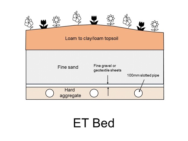
ET and ETA Beds
Evapotranspiration (ET) is the process that removes water from land covered by vegetation through evaporation (loss of water from soil or wet vegetation) and transpiration (loss of water from small openings in the leaves of plants and grasses). Evapotranspiration absorption (ETA) beds reduce reliance on effluent absorption into the soil by maximizing water loss through evaporation and transpiration. Effluent is distributed through the bed by a system of slotted pipes. Capillary action draws effluent up from a lower gravel bed through sand to supply the root zone of vegetation (usually grass) on top of the bed, to optimise evapotranspiration.
Septic tanks are the most common treatment system used with ETA beds. Common problems with ETA beds are:
- bed vegetation cover not well maintained to maximise evapotranspiration
- inadequate exposure to wind, or shading by trees, lowering the rate of evapotranspiration
- uneven distribution of effluent caused by gravity feeding instead of by a pump or pressure dosing
- beds too small for amount of effluent (hydraulic load).
The use of ET bed and ETA bed systems is restricted to certain sites and climates with restrictive soil types and soil permeability limits.
BC Zero Discharge Lagoons
The BC zero discharge lagoon is a system unique to BC. The lagoon disperses effluent by infiltration into the soil and by evaporation from the pond surface, similar in concept to an evapotranspiration absorption (ETA) bed. A BC zero discharge lagoon system consists of one or more large, excavated ponds surrounded by a berm. Sewage is fed directly from the dwelling or from a septic tank by gravity — if topography allows — otherwise a septic tank is used, and effluent is discharged to the lagoon by pump, siphon or other dosing device. Excavated clay material is placed and compacted in an elevated berm intended to prevent surface water from entering the lagoon and to provide reserve capacity. Fencing is installed on the berm, or immediately adjacent to the berm to prevent entry of animals and to provide security/safety.
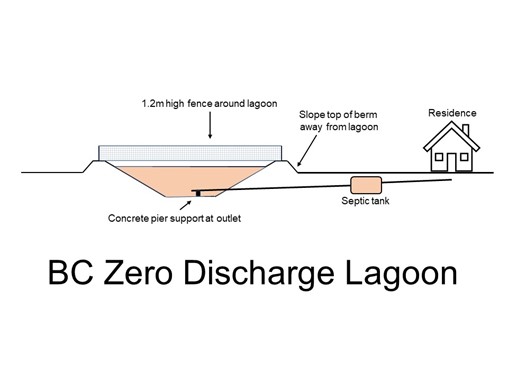
Lagoons can be rectangular or circular and the sides must be particularly sloped to prevent ice from binding against the sides and to allow egress of any persons or animals that may fall into the lagoon.
Combined Treatment and Dispersal Systems
Combined Treatment and Dispersal Systems (CTDS) are passive onsite wastewater treatment systems that treat and disperse wastewater in the same footprint. They provide treatment to Type 2 or 3 standards using media or through other processes in the same cell or unit that disperses effluent to the native soil. These systems discharge effluent at their base (or around an up-flow treatment unit) to native soil, or to sand above native soil. CTDS are typically chosen for larger scale onsite treatment solutions where restrictive factors prevent the use of other methods and where space is at a premium. They can be designed onsite or can be proprietary systems installed to manufacturers’ specifications, while also following the SSR and SPM mandates.
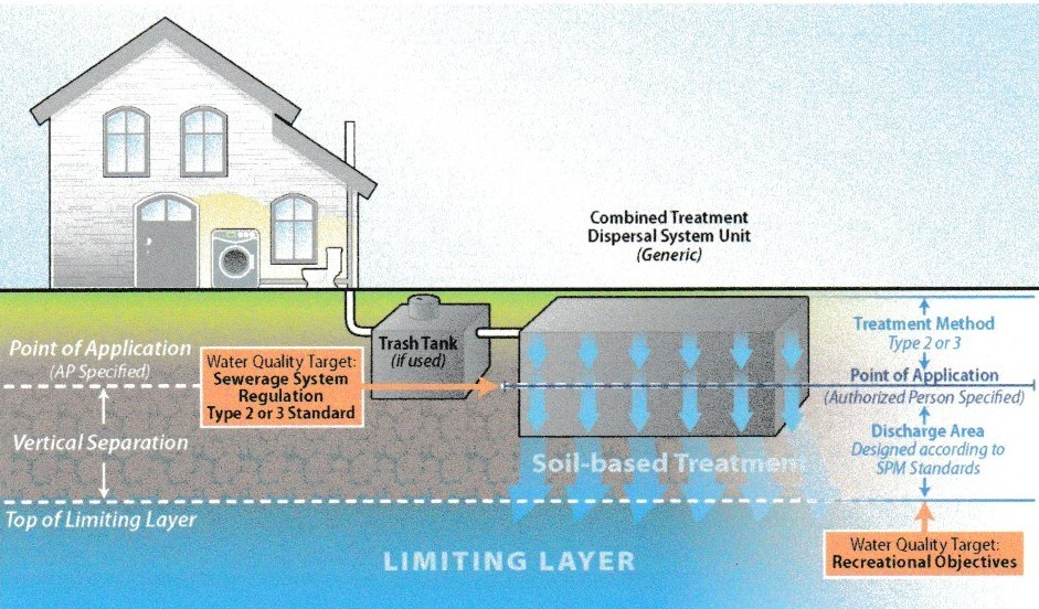
For the CTDS, the only difference in construction is that the discharge from the treatment system flows directly into the dispersal system, without any piping or pump chambers in between.
Self-Test 2
Self-Test 2
Media Attributions
- Figure 1. “Conventional Type 1 system” from United States Environmental Protection Agency is used for non-commercial, scientific and educational purposes.
- Figure 2. “Single compartment tank” from Coosa Riverkeeper is used for educational purposes under the basis of fair dealing.
- Figure 3. “Two-compartment tank” from Lake Leelanau Lake Association is used for educational purposes under the basis of fair dealing.
- Figure 4. “Septic tank with siphon chamber” from Integrated Publishing is used for educational purposes under the basis of fair dealing.
- Figure 5. “Siphon” by Camosun College is licensed under a CC BY-NC-SA licence.
- Figure 6. “Dosing tank using pump” by Camosun College is licensed under a CC BY-NC-SA licence.
- Figure 7. “Aerobic treatment unit” from United States Environmental Protection Agency is used for non-commercial, scientific and educational purposes.
- Figure 8. “Distribution box (elevation view)” by Camosun College is licensed under a CC BY-NC-SA licence.
- Figure 9. “Plastic D-box” from Polylok is used for educational purposes under the basis of fair dealing.
- Figure 10. “Typical trench with components and dimensions” by Camosun College is licensed under a CC BY-NC-SA licence.
- Figure 11. “Trickling disposal field” from EEPCO is used for educational purposes under the basis of fair dealing.
- Figure 12. “Siphon” by Camosun College is licensed under a CC BY-NC-SA licence.
- Figure 13. “Dosing tank using pump” by Camosun College is licensed under a CC BY-NC-SA licence.
- Figure 14. “Pump vault” from Infiltrator Water Technologies is used for educational purposes under the basis of fair dealing.
- Figure 15. “Pressure distribution system” by Camosun College is licensed under a CC BY-NC-SA licence.
- Figure 16. “Subsurface drip dispersal system (SDD)” by Camosun College is licensed under a CC BY-NC-SA licence.
- Figure 17. “Infiltrator® chamber” from Infiltrator Water Technologies is used for educational purposes under the basis of fair dealing.
- Figure 18. “At Grade bed” by Camosun College is licensed under a CC BY-NC-SA licence.
- Figure 19. “Alberta At Grade bed” by Camosun College is licensed under a CC BY-NC-SA licence.
- Figure 20. “Seepage bed” from Sentinel Excavating is used for educational purposes under the basis of fair dealing.
- Figure 21. “Sand mound” by Camosun College is licensed under a CC BY-NC-SA licence.
- Figure 22. “ET bed” by Camosun College is licensed under a CC BY-NC-SA licence.
- Figure 23. “BC zero discharge lagoon” by Camosun College is licensed under a CC BY-NC-SA licence.
- Figure 24. “Combined treatment and dispersal system Onsite Sewage Inspection Industry Background” is used for educational purposes under the basis of fair dealing.
Image descriptions
Figure 16. “Subsurface drip dispersal system (SDD)” image description: A labelled diagram of a subsurface drip dispersal system (SDD).
We’ve represented this diagram with an ordered list with links to jump to certain steps to match the diagram. It also has links back to the original figure at key points.
- Source
- Inlet [Return to Figure 16]
- Primary treatment
- Secondary treatment (if used)
- Pump tank & pump [Return to Figure 16]
- Filter
- Diverges to Filter flush 1 (Step 7), Pressure regulator (Step 11), or Filter flush 2 (Step 19) [Return to Figure 16]
- Filter flush 1 (optional)
- Control
- Diverges to Timed Dosing (Step 9), Automatic flush (Step 10), or Datalogging (Step 20) [Return to Figure 16]
- Timed dosing. Proceed to Step 5 – Pump tank & pump [Return to Figure 16]
- Automatic flush (unless continuous flush). Proceed to Step 18 – Flush Valve [Return to Figure 16]
- Pressure regulator (optional)
- Dose main pipe
- Dose manifold with 7 driplines connected to it and an air valve on the left-most side
- 7 Driplines with emitters
- Flush manifold with an air valve on the left-most side
- Check valve (if necessary)
- Flush main
- Flush valve (replaced by flow control if continuous system), go to Step 2 – Inlet [Return to Figure 16]
- Filter flush 2 (optional), go to Step 2 – Inlet [Return to Figure 16]
- Datalogging (optional) [Return to Figure 16]
A registered onsite wastewater practitioner or professional.
Applied Science Technologists and Technicians of British Columbia
A person who is qualified to act as a registered onsite wastewater practitioner under section 7 (1) or (2) of the Sewerage System Regulation.
Sewerage System Regulation within the Public Health Act
Sewerage System Standard Practice Manual, Version 3. Access a PDF version of the SPM online.
5-day biochemical oxygen demand
total suspended solids
A system of pipes, pumps, tanks, and other equipment used for the collection, transport, and disposal of residential wastewater (sewage). Also known as a sewage disposal system, septic system, or sewerage system.
A large cement or plastic tank into which household wastewater flows and is stored until it is pumped out.
A small building having a bench with a hole or holes through which human excretion may be evacuated into a waterproof vault or an excavated pit. Also known as an outhouse.
An area used to receive effluent discharged from a wastewater treatment method.
