Competency E2: Coordinate Cross Trade Activities
Section 12
Wiring Methods
12-010 Wiring in Ducts and Plenum Chambers
- ………
- ………
- ………
- ………
- Where a furnace cold-air return duct is formed by boxing in between joists, wiring methods specified in this section for use in the particular location shall be permitted to be used.
Wiring run within a joist space that also acts as a cold air return is approached no differently than being run through any other part of the building so long as it is protected from mechanical damage.
12-112 Conductor Joints and Splices
- Conductors shall be spliced or joined by splicing devices or by brazing, welding, or soldering with a fusible metal or alloy.
- Soldered splices shall first be spliced or loind so as to be mechanically and electrically secure without solder and then be soldered.
- Joints or splices shall be covered with an insulation equivalent to that on the conductors being joined.
- Joints or splices in conductors and cables shall be accessible.
- …………
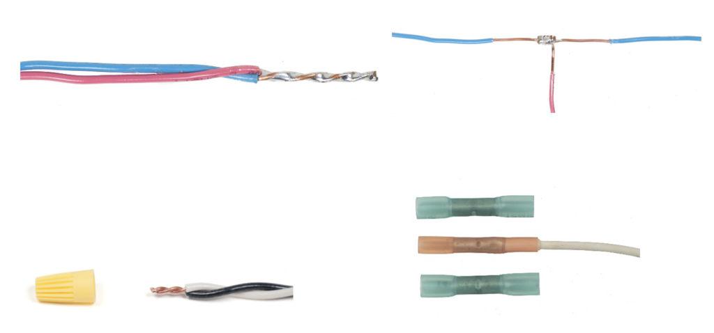
Splicing devices, such as the use of twist-on wire connectors, is the norm for joining conductors together. Soldering is a preferred method for conductor splicing but is labour intensive, so is rarely performed. Remember that soldering is not an option for joining bonding conductors. All joints and connections must be accessible, so they are made within boxes and enclosures.
12-118 Termination and Splicing of Aluminum Conductors
- Adequate precautions shall be taken in the termination and splicing of aluminum conductors, including the removal of insulation and separators, the cleaning (wire brushing) of stranded conductors, and the compatibility and installation of fittings.
- A joint compound, capable of penetrating the oxide film and preventing its reforming, shall be used for terminating or splicing all sizes of stranded aluminum conductors, unless the termination or splice is marked for use without compound.
- ………..
- ………..
- ………..
Oxidation and galvanic corrosion are the two main issues in the joining of aluminum wiring to other materials. In addition to the oxidation that occurs on the surface of aluminum wires which can cause a poor connection and resistance, aluminum and copper are dissimilar metals. As a result, galvanic corrosion can occur in the presence of an electrolyte (moisture), causing these connections to become unstable over time. The use of an anti-oxidation compound such as “Penetrox” or “Noalox” helps satisfy the requirements of the Code. It is an oxide-inhibiting compound for preventing galvanic corrosion and enhancing the connection in electrical joints. It can be used in aluminum to aluminum, aluminum to copper, and aluminum to conduit applications by providing a seal, keeping moisture and oxygen away from the connection.
12-402 Uses of Flexible Cord
- Flexible cord shall be of the types specified in Table 11 for the specific condition of use and shall be suitable for the particular location involved with respect to, but not limited to
- moisture;
- corrosive action;
- temperature;
- degree of enclosure, and;
- exposure to mechanical damage.
- ……….
- Flexible cord and cord sets shall not be used
- as a substitute for the fixed wiring of structures and shall not be
- permanently secured to any structural member;
- run through holes in walls, ceilings, or floors;
- run through doorways, windows, or similar openings;
- as a substitute for the fixed wiring of structures and shall not be
- ……….
- ……….
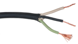
The use of flexible cord, aka extension cord, is intended for the supply of electricity to portable equipment and is not sanctioned for use as a connection to a permanent piece of equipment unless allowable in Subrule 2).
12-502 Maximum Voltage (Non-Metallic-Sheathed Cable)
Non-metallic-sheathed cable shall not be used where the voltage exceeds 300 V between any two conductors.
Non-metallic-sheathed cable (NMSC), sometimes called “Loomex” (an old manufacturer’s name) is the main type of cable used in residential wiring. It has an outer plastic sheath, insulated conductors and a bare bonding conductor as shown below. The sheath is marked as to the wire type, temperature rating and number of conductors (not counting the bonding conductor).

12-506 Method of Installation (See Appendix B)
- The cable shall be run in continuous lengths between outlet boxes, junction boxes, and panel boxes as a loop system and the joints, splices, and taps shall be made in the boxes.
- Where concealed wiring is connected to non-metallic-sheathed cable, the junction shall be made in a box.
- Where open wiring is connected to non-metallic-sheathed cable, the junction shall be made in a box or at, or in, a fitting having a separately bushed hole for each conductor.
- Where non-metallic-sheathed cable is run in proximity to heating sources, transfer of heat to the cable shall be minimized by means of an air space of at least
- 25 mm between the cable and heating ducts and piping;
- 50 mm between the cable and masonry or concrete chimneys; or
- 150 mm between the cable and chimney and flue cleanouts.
- ………..
- ………..
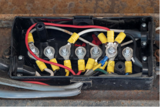
All wiring connections must be accessible, so they are to be made in a box or other acceptable enclosure, as seen in the example below.
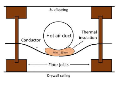
If 25 mm of free air cannot be maintained near a hot air duct, thermal insulation can be used to maintain the minimum separation provided it is installed so it cannot be accidentally dislodged as seen below.
12-510 Running of Cable Between Boxes and Fittings (See Appendix B)
- Where the cable is run between boxes and fittings, it shall be supported by straps, Type 2S or Type 21S cable ties, or other devices located
- within 300 mm of every box or fitting; and
- at intervals of not more than 1.5 m throughout the run.
- Cables run through holes in joists or studs are considered to be supported.
- ……..
- ……..
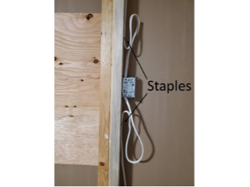
Conductors are normally stapled to a stud close to the box, often keeping a loop of conductor free for future access to pull more cable into the box if needed, as seen below.
12-516 Protection for Cable in Concealed Installations (See Appendices B and G)
- Where the cable is run through studs, joists, or similar members, the outer surfaces of the cable shall be kept a distance of at least 32 mm from the edges of the members, or the cable shall be protected from mechanical damage by
- a protector plate covering the width of the member; or
- a cylindrical bushing sized for the hole through the member, and extending a minimum of 13 mm beyond both sides of the member.
- ……..
- ……..
If a 1-inch hole is drilled dead-centre of a 2×4 stud, and a single 2- or 3-wire NMSC is installed through it, it is generally accepted that there is enough clearance between the cable and the edge of the stud to satisfy the Code Rule above. As well, if the hole is oversized there may be enough room for a drywall screw or nail to deflect and possibly not pierce the jacket of the cable. Alternatively steel protector plates are available that are fairly thick and have both hammer teeth and screw holes for attachment, however they tend to cause drywall installed over them to bulge and are fairly easy to pull off to remedy that situation, thereby negating any protection. The better choice is to install a piece of EMT or copper tubing through the hole, sized for a snug fit in the stud so that it can’t be dislodged easily and for ample interior room so a cable pulled through it doesn’t abrade the cable. Deburring the sleeve is also advisable.
12-518 Protection for Cable in Exposed Installations (See Appendix G)
Cable used in exposed wiring shall be adequately protected against mechanical damage where it passes through a floor, where it is less than 1.5 m above a floor, or where it is exposed to mechanical damage.
Two instances in house construction where an appliance does not have a cord-and-plug attachment for its electrical supply are for furnaces/ boilers and for water heaters. These appliances usually use a circuit breaker as a disconnect, so the appliance is hard-wired to the system. If above 1.5 m above the floor, the supply conductor can be NMSC; within that distance it is usually armoured cable. Conductors passing through a floor do not need protection if installed within a wall and protected as in Rule 12-516 above.
12-602 Use (of Armoured Cable) (See Appendix B)
- Armoured cable shall be permitted to be installed in or on buildings or portions of buildings of either combustible or non-combustible construction.
- Armoured cable shall be of the type listed in Table 19 as suitable for direct burial if used
- for underground runs;
- ……..
- ……..
- ……..
- ……..
- ……..
- ……..
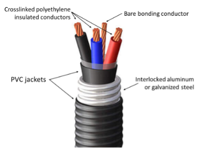
There are a few types of armoured cable listed in Table 19 “Conditions of use and maximum allowable insulation temperature of conductors and cables other than flexible cords, portable power cables, and equipment wires”. Armoured cables are used where most cables would need to be installed within conduit for protection from damage. Their CSA designations are AC90, ACWU90, ACIC, Teck90, and RA90. Armoured cables, depending on manufacturer and designation, can have insulated single or multiple aluminum or copper conductors, with or without a PVC sleeve encasing them. This assembly is located inside a flexible armour of either aluminum or galvanized steel. If the cable is to be certified for wet or underground locations, it will also have an external PVC jacket. Probably the most widely used armoured cable is Teck90®, shown below.
12-610 Terminating Armoured Cable (See Appendix B)
- Where conductors issue from armour, they shall be protected from abrasion by
- an insulating bushing or equivalent protection installed between the concutors and armour; or
- the inner jacket of an armoured cable, provided that the inner jacket is left protruding a minimum of 5 mm beyond the armour.
- ……..
- ……..
- ……..
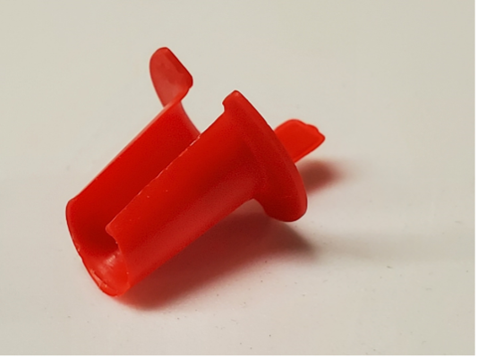
Most installers use a split bushing pushed inside the end of the cable to protect the conductors, especially if the armoured cable is of the type that doesn’t have an inner jacket. A split bushing is shown below.
12-614 Radii of Bends in Armoured Cables
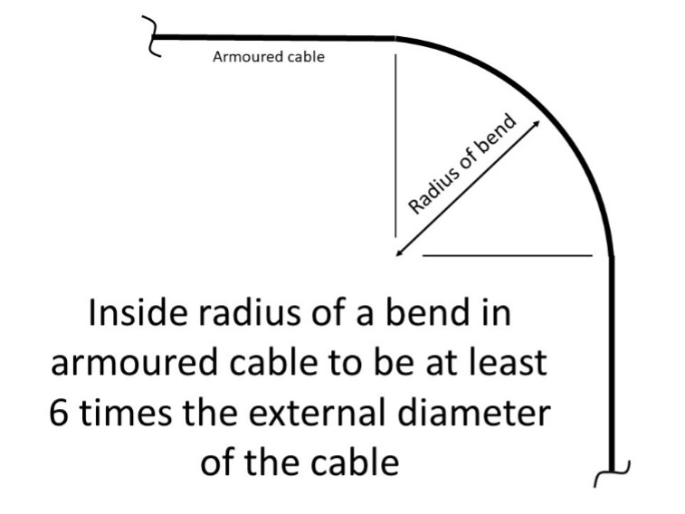
- Where armoured cables are bent during installation, the radius of the curve of the inner edge of the bends shall be at least 6 times the external diameter of the armoured cable.
- Bends shall be made without undue distortion of the armour and without damage to its inner or outer surfaces.
- ……..
For example, a bend in an armoured cable of 25 mm (1-inch) diameter would require a radius of 150 mm (6 inches).
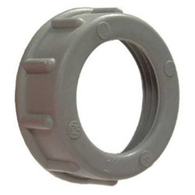
12-906 Protection of Insulated Conductors at ends of Raceways
- Bushings or equivalent means shall be used to protect insulated conductors from abrasion where they issue from raceways.
- ……..
Reaming of conduit, or the use of bushings are acceptable means for protecting conductors issuing from conduit, such as seen below.
12-91 Conductors and Cables in Conduit and Tubing (See Appendix B)
- Conduit and tubing shall be of sufficient size to permit the conductors to be drawn in and withdrawn without damage to the conductors or conductor insulation.
- ……..
- ……..
- 4) The maximum number of insulated conductors or multi-conductor cables in one conduit or tubing shall be such that the insulated conductors or cables and their coverings will not result in a greater fill than that specified in Table 8, and in this determination,
- ……..
- ……..
- ……..
- ……..
- Notwithstanding Subrule 4), the maximum permitted number of conductors of the same size in one conduit shall be permitted to be determined from Tables 6A to 6K for single insulated conductors of the appropriate construction as listed in those tables.
- ……..
Table 8 is a general statement of the amount of internal area that single conductors or multi-conductor cables are allowed to occupy in a conduit or tube, and ranges between 31% and 53% depending on their number. Subrule 4a) points to the use of Tables 9A through 9P to obtain the interior cross-sectional area of the conduit and tubing, and the area(s) of the conductor(s) or cable(s) is obtained by either measurement or by the use of Tables 6A to 6K for the specific conductor or cable. This Rule is typically used in commercial and industrial situations where conduit and EMT are used.
12-1014 Insulated Conductors and Cables in Conduit
Insulated conductors and cables installed in metal conduits and flexible metal conduits shall be in accordance with Rule 12-910.
This Rule simply fortifies the practices covered in the previous Rule when rigid and flexible metal conduits are used.
12-1108 Field Bends (in Rigid PVC Conduit) (See Appendix B)
- Rigid PVC conduit shall be permitted to be bent in the field, provided that bending equipment specifically intended for the purpose is used.
- ……..
Rigid PVC conduit is normally used with manufactured solvent-welded elbows. If approved bending equipment is not used, the act of heating and bending PVC conduit with instruments such as a torch or portable electric heat gun will cause the profile to be oval rather than round, which is unacceptable.
12-1304 Maximum Number of Conductors (in Liquid-Tight Flexible Conduit)
- The maximum number of insulated conductors and bare conductors in liquid-tight flexible conduit shall be in accordance with Rule 12-910.
- ……..
Rule 12-910 is generally used for all conduit and tubing except for HDPE (high density polyethylene conduit. This is because its wall thickness creates the smallest internal diameter of other conduit and tubing.
12-3000 Outlet Boxes (See Appendix B)
- A box or equivalent device shall be installed at every point of outlet, switch, or junction of conduit, raceways, armoured cable, or non-metallic-sheathed cable.
- ……..
- ……..
- ……..
- ……..
- At least 150 mm of free insulated conductor shall be left at each outlet for making of joints or the connection of equipment, unless the insulated conductors are intended to loop through lampholders, receptacles, or similar devices without joints.
- ……..
- ……..
- ……..
- ……..
This Rule ensures there should be enough length of conductor for future alterations that may require trimming of conductor length due to compromise from being twisted together.
12-3024 Unused Openings in Boxes, Cabinets, and Fittings
Unused openings in boxes, cabinets, and fittings shall be effectively closed by plugs or plates affording protection substantially equivalent to that of the wall of the box, cabinet, or fitting.
Covering these openings helps to prevent accidental shocks, helps to prevent hot sparks or fire from escaping if something goes wrong inside the enclosure, and helps to prevent pests from entering.
 Now complete Self-Test 8 and check your answers, quoting applicable Code rules.
Self-Test 8
Self-Test 8
Media Attributions
- Figure 25. “Some examples of acceptable wire connections” ©SkilledTradesBC, Province of British Columbia. These resources are not designed for rework, reuse, remixing, and/or redistribution; they are to be used solely for the purposes of instruction.
- Figure 26. “Flexible cord” ©SkilledTradesBC, Province of British Columbia. These resources are not designed for rework, reuse, remixing, and/or redistribution; they are to be used solely for the purposes of instruction.
- Figure 27. “Non-metallic sheathed cable” ©SkilledTradesBC, Province of British Columbia. These resources are not designed for rework, reuse, remixing, and/or redistribution; they are to be used solely for the purposes of instruction.
- Figure 28. “Conductors installed in a box” ©SkilledTradesBC, Province of British Columbia. These resources are not designed for rework, reuse, remixing, and/or redistribution; they are to be used solely for the purposes of instruction.
- Figure 29. “Conductor near hot air duct” by Camosun College is licensed under a CC BY-NC-SA licence.
- Figure 30. “Staples and wire loops near box” by Camosun College is licensed under a CC BY-NC-SA licence.
- Figure 31. “Teck90® cable” from Shawflex is used and adapted for educational purposes under the basis of fair dealing.
- Figure 32. “Split bushing for armoured cable” by Camosun College is licensed under a CC BY-NC-SA licence.
- Figure 33. “Inside radius of a bend in armoured cable to be at least 6 times the external diameter of the cable” by Camosun College is licensed under a CC BY-NC-SA licence.
- Figure 34. “Dielectric bushing for threaded conduit” from Hubbell is used and adapted for educational purposes under the basis of fair dealing.

