Competency E2: Coordinate Cross Trade Activities
Learning Task 3
Describe Electric Motors
Electric Motors
The earliest sources of electrical energy came from DC (direct current) such as batteries, however, in a direct current system there are some inherent limitations and disadvantages that have spurred on the growth of AC (alternating current) systems as a distribution medium. Over 90% of modern day generated electrical energy is AC, however, this was not an overnight decision. In the late 1880s, a variety of inventions across the United States and Europe led to a full-scale battle between alternating current and direct current distribution.
Thomas Edison, leading the charge for DC, had constructed 121 DC power stations in the United States by 1887 but it was found that, even though he proposed a system of small, local power plants that would power individual neighborhoods or city sections, high voltages could not be easily produced and transmitted. DC power was distributed using three wires from the power plant: +110 volts, 0 volts, and -110 volts. Lights and motors could be connected between either the +110V or -110V socket and 0V (neutral). 110V allowed for some voltage drop between the plant and the load (home, office, etc.) but even though the voltage drop across the power lines was accounted for, power plants needed to be located within 1 mile of the end user. This limitation made power distribution in rural areas extremely difficult, if not impossible.
A turning point in the battle came when George Westinghouse, a famous industrialist from Pittsburgh, purchased Nikola Tesla’s patents for AC motors and transmission the following year. With Tesla’s patents, Westinghouse worked to perfect the AC distribution system. The power of steam or water turned turbines which created alternating current, and transformers provided an inexpensive method to step up the voltage of AC to several thousand volts for transmission lines and then back down to usable levels in homes and businesses. At higher voltages, the same power could be transmitted at much lower current levels, which meant less power lost due to resistance in the wires. As a result, large power plants could be located many miles away and service a greater number of people and buildings. Westinghouse won a contract in 1893 to build a hydroelectric dam to harness the power of Niagara Falls and transmit AC to Buffalo, NY. The project was completed on November 16, 1896, and when AC power began to service industries in Buffalo, this milestone marked the decline of DC in the United States. While Europe would adopt an AC standard of 220-240 volts at 50 Hz (“Hertz” or old “cycles per second”), the standard in North America for the residential and light commercial users would become 120-240 volts at 60 Hz.
Electromagnetic Induction
AC systems work because of electromagnetic induction. In the 1830’s it was discovered that a conductor moving through a magnetic field, or a field moving near a conductor, created current and voltage within the conductor, as well as its own magnetic filed.
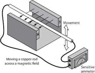
In the illustration above, as the conductor is moved upward, current will be induced in a direction that opposes that movement. If the conductor is then moved downward, the electromagnetic forces created will reverse. Those principles were key to the invention of the electric motor.
DC and Motors
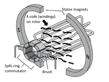
Motors take electrical energy and convert it into mechanical energy. They can operate on either DC or AC. Small DC motors are used in tools, toys, and appliances. Examples of larger DC motors currently in use are for the propulsion of electric vehicles, in elevators and hoists, and in drives for steel rolling mills. A DC motor is made up of:
- a casing containing a stator with permanent magnets (the stationary part of the motor)
- a shaft protruding from one end to which gears, pulleys and fan blades can be attached
- laminated discs containing at least three coils of wire that are attached to the shaft
- a commutator on the shaft’s end with split rings that connect the coils to brushes, and
- external terminals that are attached to the brushes.
When an external circuit is closed and DC voltage is applied to the terminals at the end of the motor, current flows through the brushes into the coils, known as “windings”, and sets up or “induces” a magnetic field around them. The magnetic field induced in the windings will be attracted and repelled by the permanent north and south magnetic fields within the stator, and the shaft will begin to rotate. The split rings of the commutator in contact with the brushes causes a reversal of the polarities within the windings as the armature passes a certain point and this maintains the rotation of the armature. If not for the split ring commutator, the motor would reach a point where there is no longer an attraction or repulsion of magnetic forces and rotation would stop. The more sets of coils there are in the armature, the smoother the rotation will be, and the less likely that the motor will stall or lock up when it reaches that state of equilibrium just mentioned. The diagram below shows the internal components of a DC motor, with the shaft and casing omitted for clarity.
For a better understanding of motors and electrical principles, check out the excellent information in some of “The Engineering Mindset” videos. Here are links to a few of them.
- Alternating Current Basics: How does an Electric Motor work? (DC Motor) [4:49]
- AC and DC Electricity: AC and DC Electricity basics [2:56]
- How DC Motors Work: How does an Electric Motor work? (DC Motor) [4:49]
- Induction Motors: Induction Motor Basics [8:38]
- How 3-phase Electricity Works: How Three Phase Electricity works – The basics explained [7:52] (originally linked: AC and DC Electricity basics [2:56])
- Main electrical panel explained: Main electrical panel explained – Load center – service panel [10:18]
Before we move on to AC motors, let’s quickly recap the operation of a DC motor. The permanent magnet is fixed in place and forms the outside static part of the motor (the stator), while coils of wire carrying the electric current fed to the motor form the rotating part of the motor (the rotor). The interaction between the permanent magnetic field of the stator and the attraction/repulsion tendencies of the temporary magnetic fields produced by the windings within the rotor is what makes the motor start to spin, and the split-ring commutator changes the polarity of the incoming DC every half rotation which keeps it spinning.
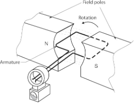
In the interests of adherence to the program outline for the piping trades, we will limit any further study to the basics of AC motors.
AC Motors
In an AC motor, windings are arranged around the inside of the casing (the stator), which are designed to produce a rotating magnetic field. Centred within the stator is a solid metal shaft onto which is affixed a conductor (a loop of wire or a coil), a cage made of metal bars, and interconnections between and within them, which makes up a freely rotating metal part (the rotor) that can conduct electricity and become a temporary magnet. Unlike in a DC motor, where power is sent to the coils in the rotor, in an AC motor the outer coils that make up the stator receive the electrical power. The coils are energized in pairs, in sequence, producing a strong magnetic field that is in constant movement around the outside of the motor.
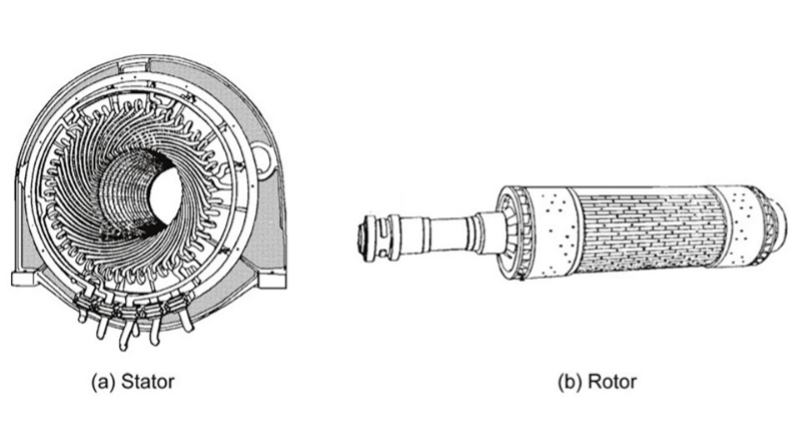
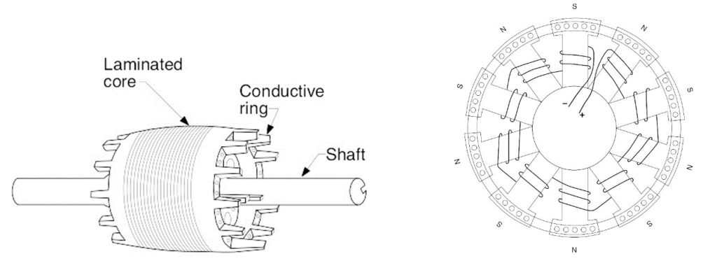
Remember that the rotor, suspended on bearings or bushings inside the magnetic field, is an electrical conductor. The stator’s magnetic field, fed with alternating current, is constantly changing so, according to the laws of electromagnetism, the magnetic field induces an electric current inside the rotor. The current induced in the rotor produces its own magnetic field and, according to another law of electromagnetism (Lenz’s Law) tries to stop whatever it is that causes it (the rotating magnetic field) by rotating as well. You can think of the rotor as frantically trying to “catch up” with the rotating magnetic field in an effort to eliminate the difference in motion between them. Electromagnetic induction is the key to why a motor spins, and that’s why it’s called an induction motor.
3-Phase Power
To understand three-phase motors, it is useful to first understand three-phase power.
In electrical power generation, electricity is produced by using a power source such as water or steam in a turbine to spin a generator that is similar in its components to an electric motor, although much more massive in size. The generator’s size and number of windings create alternating current which changes in amplitude and frequency over time. If shown graphically with the amplitude on the vertical y-axis and time on the horizontal x-axis, the relationship between the voltage or current vs. time for one set of windings (a “phase”), through one complete rotation or “cycle” of the armature (rotor) would resemble a sinusoidal or “sine” wave as shown below.
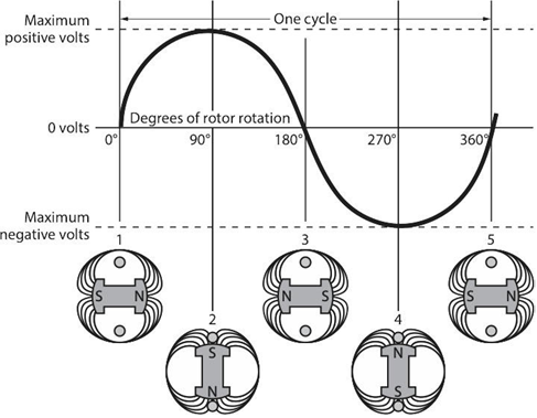
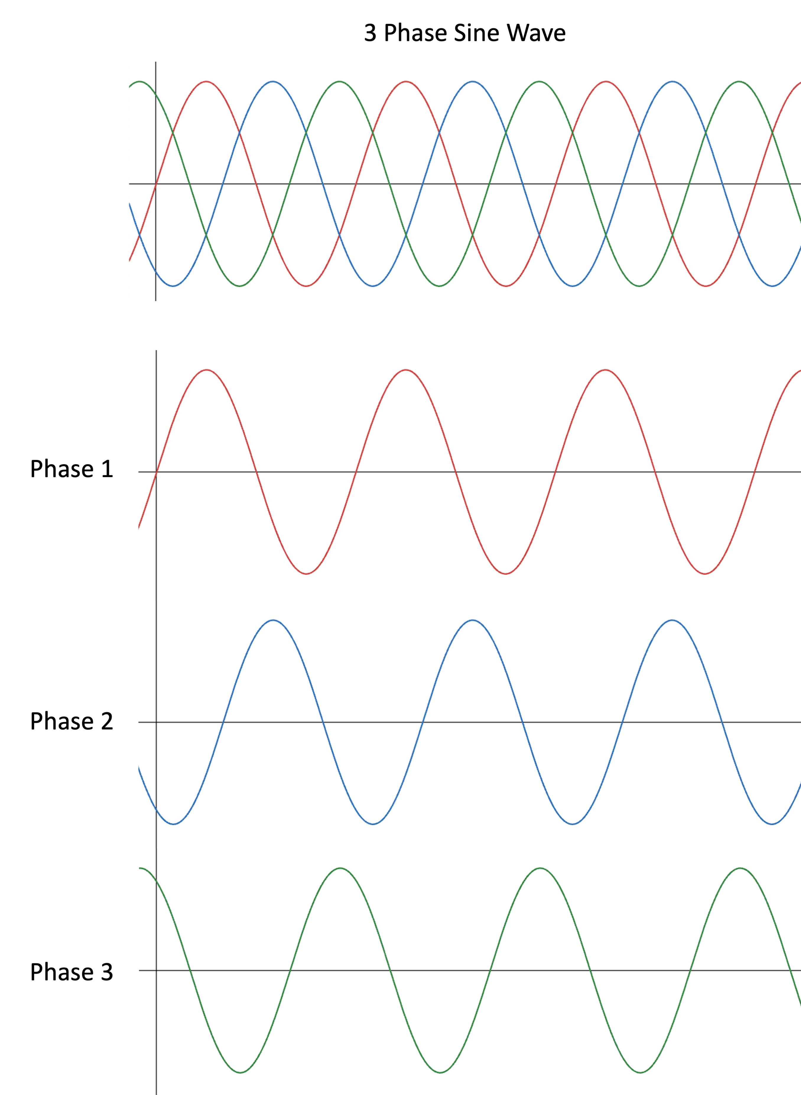
The graph shown above is the result of one set of windings rotating 360 degrees creating alternating current. Add another 2 sets of windings on the same spinning armature and there will be 3 alternating currents or phases produced simultaneously. If the windings are spaced evenly around the armature, their sine waves will be 120 degrees apart as well. There is nothing magical about three-phase power. It is simply three single phases synchronized and offset by 120 degrees. The diagram below shows the effect of the three sets of windings spinning on the same armature (top illustration) and each of the three windings or “phases” shown by themselves below it.
The three-phase alternating current leaves the generator and enters a transmission substation at the power plant where large transformers convert the generator’s voltage (which is already at the thousands of volts level) up to extremely high voltages for long-distance transmission on the power transmission grid. Typical voltages for long distance transmission are in the range of 155000 to 765000 volts to reduce line losses. The extremely high voltages are stepped down at distribution stations by transformers and are then fed to different areas surrounding the station at a voltage value somewhere around 7200 volts AC. 3-phase AC electricity is confined in its use to commercial and industrial areas where more power is needed to operate large motors and heaters, so transformers will often reduce the voltage in these applications to around 600 volts of 3-phase power. 3-phase transformers for commercial buildings may be of lower output voltages such as 480 and 400 volts.
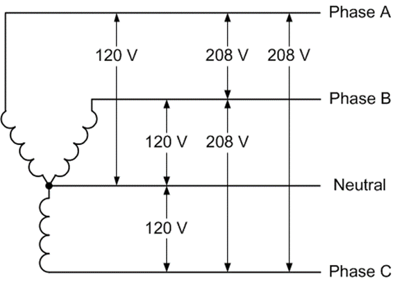
The 3-phase power can be of either a Delta or a Wye configuration. These terms refer to the way the three secondary coils of the transformer secondary have been connected.
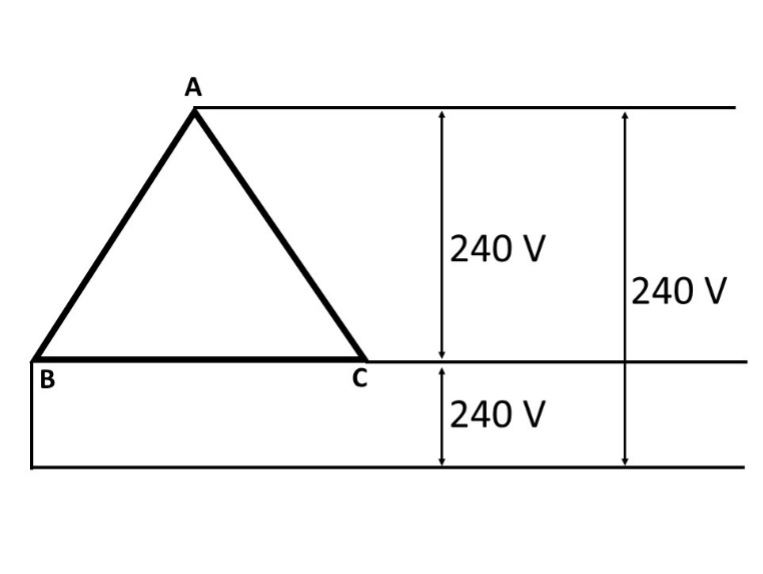
3-phase Delta systems are normally used for powering loads that don’t require a neutral, such as large motors or heaters. Generation plants typically send power out through this configuration as there is no need for the expense of a fourth neutral wire over what may be very long distances.
Distribution transformer secondarys are wired either as Delta or Wye configurations, again usually being determined by the intended uses of the power. The advantage of a Wye configuration is that, with the fourth wire (neutral) it allows the transformer to deliver power for both single-phase as well as 3-phase loads. Note that in the 3-phase Wye diagram below, the line-to-neutral (hot-to-neutral) voltages are all at 120 volts, but the line-to-line (hot-to-hot) voltages are 208 volts. This is because of the phases being 120° apart, where, if one of the phases is at peak voltage, the other line isn’t. If two hot lines were 180° apart, as they are in 120 volt split-phase residential systems, the line voltage is added together to result in 240 volts, which powers appliances such as clothes dryers, ranges, and hot water tanks. Combining two hot 120-volt phases in a 3-phase system results in 208 volts, which is 120 volts × 1.732 (the square root of 3 which represents the two phases being 120° apart). The explanations and calculations that would be used to illustrate that phenomenon are best left to another time and trade.
Split-Phase Power
For safety’s sake, and due to the absence of motors and other loads that would require a higher and more efficient power supply, houses aren’t fed with 3-phase power. The transformers at the street will step one leg or phase of the incoming power down to 240 volts and will tap a neutral into the middle of the secondary coil. This delivers two 120-volt hot wires that are 180° out-of-phase from each other and a neutral to the house, as shown in the diagram below.
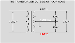
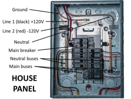
When the two hot legs (Line 1 and Line 2) are wired to an appliance, the voltage difference between them is 240 volts (+120 minus -120 = 240). Electric hot water tanks are wired with just the two hot leads and no neutral because there is no need for a 120V control circuit. Electric dryers and ranges have their 120V control circuits powered by tapping into one of the 120V hot legs and providing a return path to the panel via the neutral wire, so they are 3-wire circuits (two 120-volt hots and a neutral). A common house panel is shown below. The bus connections are staggered, so any two adjacent breakers will be in contact with the L1 and L2 (main) buses. If both breakers feed an appliance, such as through the red and black wires on the right side of the panel, it will be supplied with 240 volts. The switch levers of the two breakers must be tied together so they operate as one.
Induction Motors
Induction motors pass an alternating current through coils in the stator which produces a magnetic field, and the oscillating frequency of the AC supply will cause this magnetic field to rotate. The rotating magnetic field (RMF) will then induce opposing magnetic fields in the rotor and cause useful rotation. Both 3-phase and single-phase use this principle, however, the magnetic field produced by 3-phase current will naturally rotate due to the phases being 120° apart. The stator in a 3-phase motor will have a minimum of 2 sets of windings for each phase, as seen in the diagram below.
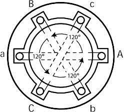
The coils are on opposite sides of the stator from each other so the powerful magnetic fields resulting from current flowing through them will cause induced current in the rotor and the rotor will spin. The rotor’s direction of rotation can be reversed by reversing the positions of any two of the three incoming power legs on their terminal connections.
Single-Phase Motors
The single-phase induction motor is a popular motor with the advantages of being cheap, reliable, and able to connect directly to single-phase power, making them especially common in domestic and small commercial appliances. However, unlike three-phase motors, they are not self-starting and require an additional winding driven by a capacitor to accelerate from a standstill. For an induction motor to start running, a rotating magnetic field (RMF) must be produced in the stator, which induces rotation and torque in the rotor. Since the stator does not physically move, the rotation of the magnetic field is produced by the interaction between electromagnetic forces produced in the stator windings. In a three-phase motor, with each winding supplied by a voltage that is 120 degrees out of phase with the other windings, the sum of the forces produced creates a rotating magnetic field (RMF). This means that three-phase power can induce torque in the rotor at a standstill, and three-phase motors can self-start without additional components.
However, a single-phase induction motor is fed by a single-phase power supply that runs through a single stator winding. One stator winding on its own cannot produce an RMF – it merely produces a pulsing magnetic field that is made of two opposing fields spaced 180 degrees apart. This creates two problems:
- first, the motor is not self-starting because the magnetic field produced by the stator is not rotating; and
- secondly, although a single winding can drive the motor once it gets up to speed, it does not produce a consistent torque in the rotor during a full revolution, which leads to a loss of efficiency and performance.
The rotor experiences maximum torque at approximately 10% slip (the difference in rotation between the rotor and the stator winding). Therefore, the rotor will spend a large part of each revolution experiencing very low torque.
Auxiliary Winding
In addition to the “run” windings within the stator, single-phase induction motors use a second stator winding to overcome these problems, called an ‘auxiliary winding’ or ‘start winding.’ This winding is rotated 90 degrees away from the main winding, and, by means of a capacitor that changes the phase of the supply voltage, it is fed by a voltage that is out of phase with the voltage supplied to the main winding. This means that the interaction between the two windings produces a rotating magnetic field, and the motor can self-start.
There are two capacitors with different characteristics used by single-phase induction motors for different aspects of their operation.
Start Capacitors
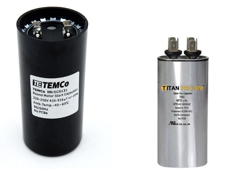
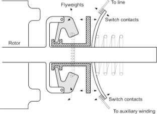
A start capacitor is one that is used to provide starting torque to the motor. They are electrolytic capacitors with relatively high losses and low efficiency and are not designed for continuous duty, so it is necessary to disconnect them once the motor gets up to speed using a centrifugal switch or relay of some kind.
The flyweights in the centrifugal switch shown below move outward from the shaft and, in doing so, move the collar to which they are attached to the right. This breaks the contacts between the line voltage and the start capacitor of the auxiliary winding. This happens at approximately 75% of the motor’s rated speed.
Run Capacitors
A run capacitor is used to smooth the motor’s torque during each revolution, increasing efficiency and performance. It is usually much smaller than a start capacitor and of the oil-filled type to reduce energy losses.
Limitations of Single-Phase Motors
Even with the additional auxiliary winding, a single-phase induction motor suffers from several limitations compared to a three-phase motor. The phase shift provided by a run capacitor changes with the motor’s speed, which means efficiency is not consistent as the motor changes speed. Efficiency is also affected by RMF being produced by two stator windings. It is not as close to a perfect circle as a three-phase RMF, meaning that torque still varies considerably during each revolution, reducing performance and increasing vibration. The components required to make single-phase induction motors self-starting, including the capacitors and centrifugal switch, provide an opportunity for thermal and mechanical wear to create maintenance problems.
Induction Motors and “Slip”
Both single- and three-phase motors are also known as “asynchronous” induction motors, as the frequency of their AC current does not directly match the number of rotations of the output shaft. This phenomenon is known as “slip” and occurs because the rotor is always playing a magnetic game of “catch-up” with the RMF. The existence of slip means precise timing is difficult with induction motors. Slip is acceptable in situations where precise timing isn’t required.
Synchronous Motors
Synchronous motors cover the bases that induction motors cannot, namely their “asynchronous” nature. Synchronous motors match the output rotational frequency to the input AC frequency, allowing designers to use these motors in precisely timed applications, such as clocks, rolling mills, record players, and more. They accomplish this feat by linking the magnetic poles (the north-south pairs in every magnetic field) of the stator and rotor, so that the stator RMF will turn the rotor at exact, synchronous speeds. Synchronous motors, while generally more expensive than induction motors, sport higher efficiencies. The lack of complexity of induction motors is the best advantage that they have over synchronous designs. They are very simple to manufacture, operate, and maintain, and is why induction motors are by and large less expensive than synchronous motors. Conversely, implementing a synchronous machine requires a more complex rotor, which is more difficult to manufacture/repair, and requires additional circuits that must be bought and installed so that these motors can operate effectively.
In some cases, synchronous motors can achieve efficiencies of >90% and are generally more energy-efficient than induction motors. The efficiency depends on the specific motor type and size, but the lack of slip in synchronous motors means there is less energy lost in converting between electrical energy and mechanical energy. Finally, a common theme between synchronous motors and induction motors is their price separation. For reasons previously explained, synchronous motors are more expensive to produce, implement, maintain, and repair than induction motors, and so are less commonly used.
Speed Control for Motors
A variable frequency drive (VFD) is a type of motor controller that adjusts the speed of an electric motor by varying the frequency and voltage supplied to it. Other names for a VFD are variable speed drive, adjustable speed drive, adjustable frequency drive, AC drive, microdrive, and inverter.
Frequency (or hertz) is directly related to the motor’s speed (RPMs). In other words, the faster the frequency, the faster the RPMs. If an application does not require an electric motor to run at full speed, the VFD can be used to ramp down the frequency and voltage to meet the requirements of the electric motor’s load. As the application’s motor speed requirements change, the VFD can simply turn up or down the motor speed to meet the speed requirement. While VFDs are the standard for speed control of 3-phase motors, slowing down single-phase motors is a more difficult task, especially if it is of the type that uses a centrifugal switch to disconnect the start windings. Always make sure to use a speed control that is recommended for a specific type of motor.
Motor Control
Small fractional horsepower single-phase motors used in residential applications are normally controlled using a simple on/off switch. Large single- and three-phase motors in commercial and industrial applications need more protection due to their relative size and cost. Combination motor controllers are normally used for these motors.
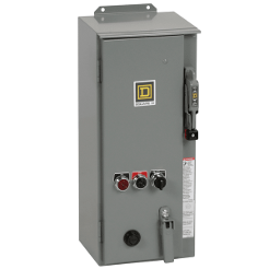
The following are the most fundamental functions that a combination motor controller performs:
On/off control: The starter controls the opening and closing of the power electrical circuit. The switching is done by the main contacts (poles) of the relay, known as a contactor. An electromagnetic coil is energized, which open or close the contacts. The electromagnetic coil has a nominal control voltage and can either be an AC or DC voltage.
Short-circuit protection: In industrial applications, normal load current can be up to thousands of amperes and in the case of a short-circuit fault, the fault current can go over 100000 amperes, and this can cause severe damage to the equipment. The short-circuit protection disconnects the supply and prevents the potential damage in a safe manner. Short circuit protection is provided by fuses or circuit breakers in a combination motor controller.
Overload protection: When a motor draws more current than it is designed to, an overload condition is caused. The main objective of an overload relay is to detect the excess currents and open the circuit to prevent the motor from burning out or overheating. Electronic or electromechanical overload relays are used in combination with a contactor to provide the required overload protection.
Disconnecting and breaking: To prevent an unintended restart, it is required to disconnect the motor from the main power circuit. As well, In order to safely perform maintenance on a motor or starter, a motor must be able to be isolated from the power. The disconnect switch of the circuit provides this function. Disconnecting and breaking is provided by a disconnect switch or circuit breaker in a combination motor controller.
For an excellent online video that explains the wiring and functions of a single-phase motor starter, watch Single Phase Direct Online Starter DOL Wiring Diagram Connections Explained – AM2, AM2S, AM2E [15:24]
Watch Star Delta Starter Explained – Working Principle [11:07] for an informative video on the starting controls for 3-phase motors.
Motor Enclosures
Motors have two basic types of enclosures—open and enclosed. Open enclosures allow for the free flow of air through the motor internals for cooling while those that are enclosed greatly restrict or prohibit the entry of outside air. The basic designs used in applications are described below.
Open Drip Proof
The open drip proof (ODP) enclosure is intended for installation in clean and dry environments and tends to be the standard in indoor applications. An internal fan circulates ambient air through the enclosure and provides a highly efficient cooling process.
Totally Enclosed Fan Cooled
The totally enclosed fan cooled (TEFC) enclosure is designed for outdoor installation and dirty or dusty indoor applications. Special TEFC designs are also used in processing plants in which periodic wash down is required. Unlike the ODP enclosure, it uses an external fan to force ambient air over the motor’s exterior surface.
Totally Enclosed Air Over
The totally Enclosed Air Over (TEAO) enclosure is designed for damp or wet environments in which the driven machine provides the air flow required for cooling. A common application is cooling tower fans. TEAO motors often have multiple horsepower ratings, and the usable horsepower depends upon the velocity and temperature of the air flowing over the motor.
Totally Enclosed Non-Ventilated
The totally enclosed non-ventilated (TENV) enclosure is designed for dusty environments and is usually limited to 5 horsepower and less. It uses raised fins over the motor surface area to transfer heat to the surrounding air without the aid of an external fan.
Hazardous Locations
Hazardous location motors are a totally enclosed design that are intended for use in potentially dangerous areas. The Class I, Explosion Proof (XP) enclosure is a special type that is designed for use in locations in which potentially explosive liquids and gases may be present. Class II enclosures are used in locations that are subject to combustible dusts, such as coal and grains. The area where the rotor shaft exits the enclosure is designed to contain any sparks that could occur inside the motor enclosure.
Nameplate Information
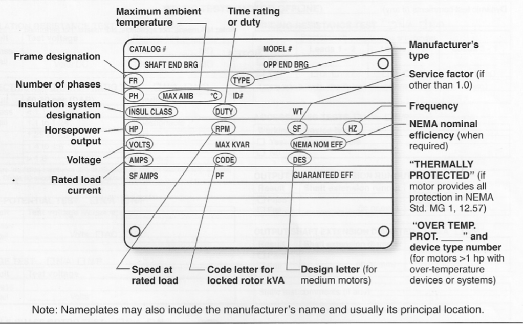
NEMA MG-1 requires that certain information be included on the nameplate of all single- and three-phase motors. Typical nameplate information may include, but is not limited to expressions of horsepower, volts, amps, Hz, phase, rpm, insulation class, enclosure, frame size, efficiency, service factor, power factor, duty, ambient, code and design. Most terms are straightforward but there are several that require further explanation. An example of a motor nameplate is shown below. Note that, whenever replacing a motor, a photo of its nameplate passed on to a supplier is the easiest and most advisable way to ensure replacement compatibility.
Efficiency
Efficiency (Eff) defines how well a motor converts electrical energy into mechanical energy. The motor’s full load efficiency is shown on the nameplate, and it is often less than the actual maximum efficiency. Maximum motor efficiency typically occurs between 70 percent and 95 percent of full load, and most NEMA motors can be operated as low as 60 percent of full load without any significant loss in efficiency.
Service Factor
Service factor (SF) is a multiplier that indicates the actual horsepower that the motor can deliver over and above the nameplate horsepower. For example, if a 10-horsepower motor has an SF of 1.15, it is designed to deliver 11.5 horsepower without overloading. SF is intended to handle small, intermittent overloads, occasional increases in ambient temperature and periods when the actual voltage is lower than the nameplate voltage.
Power Factor
Power factor (PF) is the ratio of active power in watts to the apparent power in volt-amps at full load. A motor can be designed for high efficiency or high PF but not both. Since efficiency cannot be enhanced in the field, motors are designed for high efficiency and the trade-off is lower PF.
Duty
Duty defines the length of time that the motor can operate while meeting its other nameplate ratings. Most industrial motors are rated for continuous duty while certain special application motors will show intermittent run times in minutes. Electrical code definitions for duty are covered in the following section.
Ambient Temperature
Ambient temperature is the maximum allowable temperature of the air surrounding a motor when it is operated continuously at full load. A typical ambient rating is 40 °C (104°F).
Code Letters
Code letters (A – V) provide the range of current required (locked rotor current or LRC) during across-the-line starting for a particular motor. The value indicated by the code letter is in units of KVA/horsepower. A typical industrial motor will require five to seven times the full load current during starting.
Design Letters
Design letters (A-D) indicate the shape of the torque curve produced by a particular motor. Design B is the standard for industrial duty motors, Design C provides a higher starting torque while Design D is a high slip motor that provides the highest starting torque. Design A is a special purpose motor that offers the highest pullout torque.
 Now complete Self-Test 2 and check your answers.
Self-Test 2
Self-Test 2
Media Attributions
- Figure 1. “Inducing a current in a conductor moving within a magnetic field” ©SkilledTradesBC, Province of British Columbia. These resources are not designed for rework, reuse, remixing, and/or redistribution; they are to be used solely for the purposes of instruction.
- Figure 2. “DC motor components” ©SkilledTradesBC, Province of British Columbia. These resources are not designed for rework, reuse, remixing, and/or redistribution; they are to be used solely for the purposes of instruction.
- Figure 3. “Another simplified view of a DC motor” ©SkilledTradesBC, Province of British Columbia. These resources are not designed for rework, reuse, remixing, and/or redistribution; they are to be used solely for the purposes of instruction.
- Figure 4. “Stator and rotor of an AC motor” ©SkilledTradesBC, Province of British Columbia. These resources are not designed for rework, reuse, remixing, and/or redistribution; they are to be used solely for the purposes of instruction.
- Figure 5. “Side and end views of an AC rotor” ©SkilledTradesBC, Province of British Columbia. These resources are not designed for rework, reuse, remixing, and/or redistribution; they are to be used solely for the purposes of instruction.
- Figure 6. “Sine wave of single phase alternating current and rotor position in time” ©SkilledTradesBC, Province of British Columbia. These resources are not designed for rework, reuse, remixing, and/or redistribution; they are to be used solely for the purposes of instruction.
- Figure 7. “Graph showing sine waves of 3-phase alternating current over time, and individual phases within it” by BCcampus is licensed under a CC BY-NC-SA licence.
- Figure 8. “3-phase Delta wiring” by Camosun College is licensed under a CC BY-NC-SA licence.
- Figure 9. “3-phase Wye wiring” by Fulai Yao & Yaming Yao is licensed under a CC BY 4.0 licence.
- Figure 10. “Split-phase power to residential buildings” from the International Journal of Advanced Research in Science, Communication, and Technology (IJARSCT) is used for educational purposes under the basis of fair dealing.
- Figure 11. “House Panel” by Camosun College is licensed under a CC BY-NC-SA licence.
- Figure 12. “Stator showing 3 sets of opposed windings (Aa, Bb and Cc)” ©SkilledTradesBC, Province of British Columbia. These resources are not designed for rework, reuse, remixing, and/or redistribution; they are to be used solely for the purposes of instruction.
- Figure 13. “Start (left) and run (right) capacitors”
- Start (Left): from TEMCo Industrial LLC is used for educational purposes under the basis of fair dealing.
- Run (Right): from Packard is used for educational purposes under the basis of fair dealing.
- Figure 14. “Centrifugal switch” ©SkilledTradesBC, Province of British Columbia. These resources are not designed for rework, reuse, remixing, and/or redistribution; they are to be used solely for the purposes of instruction.
- Figure 15. “Combination motor control” from RS Industrial Solutions & Electronic Components is used for educational purposes under the basis of fair dealing.
- Figure 16. “AC motor nameplate” ©SkilledTradesBC, Province of British Columbia. These resources are not designed for rework, reuse, remixing, and/or redistribution; they are to be used solely for the purposes of instruction.
Image Description
Figure 9. “3-phase Wye wiring” image description: A labeled diagram of 3-phase wye wiring. On the right side of the diagram, the phases are labeled from top to bottom as Phase A, Phase B, Neutral, and Phase C. The diagram indicates the following voltage relationships:
- 208V between Phase A and Phase C
- 208V between Phase A and Phase B
- 208V between Phase B and Phase C
- 120V between Phase B and Neutral
- 120V between Neutral and Phase C
- 120V from Phase A to Neutral
The wye connection is shown on the left side of the diagram, where all three phases and the neutral meet at the center of the wye configuration. [Return Figure 9]

