Competency F4: Install Hydronic Systems
Learning Task 2
Describe commissioning procedures for hydronic systems, components, and controls
Design requirements
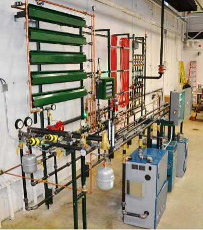
Designing a hydronic system (Figure 2) involves several important requirements for efficient and effective operation. To start, a heat loss calculation determines the heating or cooling load for the space or building that the hydronic system will serve. This calculation considers factors like sun exposure, insulation, window sizes, climate, and occupancy to determine the required heating or cooling capacity. Appropriate components are chosen for the system needs, including boilers or heat sources, pumps, piping, radiators, or other terminal units, expansion tanks, and controls. These components must be sized correctly for the load. The piping layout is designed with even heat distribution or cooling in mind. Proper pipe sizing, insulation, and lay out are crucial to minimize heat loss and maintain system efficiency. An appropriate heat transfer fluid must be determined, usually water or water mixed with an antifreeze solution such as glycol and it must be maintained at the right temperature and pressure to prevent freezing or overheating.
Thermostats and control valves help maintain the desired temperature within the space. Many systems include zoning to allow for temperature control in different areas. The system is balanced so that each radiator or terminal unit receives the correct flow of water, preventing uneven heating or cooling. Flow control valves or balancing valves have this job. Pressure relief valves, backflow preventers, and temperature controls must be installed to protect against system failures and keep the system safe.
Pipes and components are properly insulated to minimize heat loss and maintain system efficiency. This is especially important for outdoor piping and equipment.
Correct pump sizing is critical to efficiently circulate water through the system. Variable-speed pumps may be used to modulate flow rates based on demand. Water quality is monitored and clean, deionized water should be used. Regular maintenance is required to prevent corrosion, scale buildup, and other issues that can affect system performance. Considerations should be made so that the hydronic system integrates well with other HVAC components, such as air handlers, heat exchangers, and ventilation systems. Energy-efficient systems are designed by using high-efficiency boilers or heat sources, properly sized pumps, and efficient controls that can adjust based on load.
Consider ease of access for maintenance and repairs. Burners will need to be pulled out and cleaned. Hot surface igniters will need to be replaced. Make sure that components are accessible and that there is a maintenance plan in place. Follow all local building codes, regulations, and standards applicable to hydronic systems and comply with safety and environmental requirements.
Keep detailed records and documentation of the system design, installation, and maintenance. Always keep the manufacturer’s materials with the equipment. This information is valuable for troubleshooting and future modifications. Test the system thoroughly before handing it over to the building owner or occupants and confirm that it operates according to design specifications.
Safety features
Safety features in a hydronic system are needed for protecting both the system itself and the occupants of the building. These features are designed to prevent accidents, minimize risks, and keep the system operating safely.
A pressure relief valve is installed on the boiler or pressure vessel to prevent over pressurization. It automatically opens to release excess pressure if the system pressure exceeds a safe limit. In gas-fired systems, flame safeguard controls monitor the presence of a flame. If the flame is lost or fails to ignite properly, these controls shut down the burner to prevent gas buildup and potential explosions. An expansion tank is part of a closed-loop hydronic system. It accommodates the expansion and contraction of the fluid due to temperature changes, preventing excessive pressure buildup.
Air vents help remove trapped air from the system, which can reduce efficiency and impair performance. Proper air elimination helps maintain safe and efficient operation. Backflow preventers are installed to prevent the contamination of the potable water supply by the hydronic system. They that water in the hydronic system flows in one direction only.
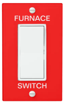
Temperature and pressure gauges provide visual monitoring of the temperature and pressure within the system, allowing operators to identify potential issues. Circulator pumps may have overload protection features that shut down the pump if it becomes overloaded or blocked, preventing damage to the pump. Zone valves and zone control systems allow for the isolation of individual heating or cooling zones, ensuring that only the necessary areas receive heating or cooling, which can improve safety and efficiency. An easily accessible emergency shutoff switch can be used to quickly deactivate the entire system in case of an emergency.
Systems that involve combustion or are atmospherically vented, such as gas-fired boilers, must meet ventilation and combustion air requirements to verify proper air supply and prevent the buildup of harmful gases. In systems that use combustion, CO detectors can be installed to monitor CO levels and provide an alarm if dangerous levels are detected.
In some commercial or industrial applications, fire suppression systems may be integrated with hydronic systems to provide added protection in the event of a fire.
Limits
High temperature limit controls monitor the temperature of the fluid in the system. If the fluid temperature exceeds a predetermined limit, the control shuts down the heating source to prevent overheating.
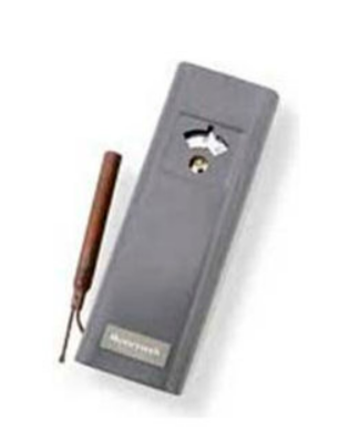
Low water cut offs or LWCO devices are designed to protect boilers from damage caused by low water levels. If the water level in the boiler drops below a safe threshold, the LWCO shuts down the burner to prevent overheating.
Temperature drop
In a hydronic heating or cooling system, the term “temperature drop” refers to the difference in temperature between the supply (hot) and return (cold) water or fluid in the system as it circulates through various components and zones. This temperature drop is a critical parameter in hydronic systems and plays a significant role in system performance and efficiency. The specific target temperature drop in a hydronic system can vary depending on factors like design, climate, and system type. System designers and installers aim to achieve an appropriate temperature drop to meet the heating or cooling needs of the building efficiently. Temperature drop or the ▲T is typically 20 degrees.
In a hydronic heating system, the primary function is to transfer heat from the heat source (e.g., boiler, heat pump) to the spaces being heated (e.g., rooms, floors). In a cooling system, the goal is to remove heat from the spaces. The heated or chilled water or fluid is distributed through a network of pipes to various zones or heat emitters (e.g., radiators, baseboard heaters, underfloor heating, or cooling coils). The water is initially sent out from the heat source as “supply water” at a specific temperature.
As the supply water flows through the heat emitters or cooling coils, it releases or absorbs heat, depending on whether it’s a heating or cooling system. This process results in the supply water’s temperature changing. The now “return water” is the water that has completed its circuit through the distribution system and has absorbed or released heat. It returns to the heat source at a different temperature.
The temperature drop is the difference in temperature between the supply water leaving the heat source and the return water returning to it. In a heating system, this temperature drop represents the amount of heat that was delivered to the zones. In a cooling system, it represents the amount of heat that was removed from the zones.
The temperature drop is an important parameter for several reasons:
- A larger temperature drop typically indicates that more heat (or cooling) has been transferred to the spaces, which is more efficient. Smaller temperature drops may suggest that the system is not delivering as much heating or cooling as desired.
- Understanding the temperature drop helps in balancing the system. Balancing involves adjusting flow rates and control settings to confirm that each zone receives the right amount of heating or cooling. Zones with a larger temperature drop may require adjustments to achieve balance.
- Many hydronic systems use temperature sensors to control the operation of the heat source or chillers. These sensors monitor the return water temperature, and if it deviates from the desired setpoint, the system adjusts accordingly.
- Maintaining an appropriate temperature drop ensures that the system operates efficiently, which can save energy and reduce operating costs.
- Accurate control of the temperature drop helps maintain consistent and comfortable indoor temperatures throughout the building.
- Monitoring the temperature drop can be helpful for diagnosing issues in the system. For example, if the temperature drop is too small, it may indicate insufficient heat transfer, while a very large drop could suggest overworking the equipment.
System balancing
Balancing a hydronic system allows for efficient operation and even heat or cooling distribution throughout a building. Balancing involves adjusting the flow rates of water in different parts of the system, such as radiators or heating/cooling zones, to achieve a uniform temperature and optimal performance.
Before starting the balancing process, gather information about the hydronic system, including its design, components, and specifications. Examine the original design plans and specifications to understand how the system was intended to operate. This information will serve as a reference point during the balancing process. Measure the flow rates of water in the various branches or zones of the hydronic system. This can be done using flow meters, pressure gauges, or temperature sensors. Monitor the pressure differential across different components of the system, such as valves, pumps, and heat emitters (e.g., radiators or underfloor heating systems). Pressure differentials can indicate imbalances in flow rates. Use balancing valves or adjustable flow control valves at key points in the system to regulate the flow of water. These valves can be adjusted to restrict or increase the flow as needed. Focus on individual zones within the system, such as specific rooms or areas. Adjust the flow rates to achieve the desired temperature and comfort level in each zone.
For radiators or baseboard heaters, balance the flow by partially closing or opening radiator valves.
For underfloor heating systems, use flow restrictors or manifold adjustments to balance flow to different loops. Determine whether the system operates on a constant flow or variable flow basis. Constant flow systems maintain a consistent flow rate, while variable flow systems adjust flow based on demand. For variable flow systems, use differential pressure control valves to maintain stable pressure differentials across components. Monitor temperature differentials between the supply and return lines of the system. Adjust flow rates to maintain the desired temperature differential, to allow for efficient heat transfer. Install hydronic balancing valves in critical locations to simplify and enhance the balancing process. These valves provide visual indicators of flow rates and pressure differentials, making adjustments easier. Periodically re-measure flow rates, pressure differentials, and temperature differentials to make sure that the system remains balanced. Make further adjustments as necessary to maintain consistent performance.
Flow rates (zones)
Flow rates determine the volume of water circulating through the system and directly impact its performance and efficiency. The design flow rate is the flow rate of water that the system is designed to operate at to meet the heating or cooling load of the space or building. It is typically calculated during the system design phase based on factors like the building’s size, insulation, climate, and desired temperature differential. Flow rates in hydronic systems are often measured in gallons per minute (GPM). The design flow rate is usually specified in GPM to maintain required heating or cooling capacity.
The pump flow rate is the rate at which the system’s circulation pump moves water through the pipes and components. It should match the design flow rate for efficient operation. The pump’s flow rate is typically adjustable to accommodate changes in system demand.
In larger hydronic systems with multiple heating or cooling zones, each zone may have its own flow rate requirement. The flow rate can be adjusted for individual zones using zone valves or variable-speed circulators to maintain the desired temperature in each area.
Balancing flow rates involve adjusting the flow of water to different radiators, coils, or terminal units within the system. This provides even heating or cooling throughout the space. Balancing valves or flow control valves may be used for this purpose.
Delta-T or (ΔT) represents the temperature difference between the supply and return water in the hydronic system. A larger delta-T indicates more efficient heat transfer. By controlling the flow rate and adjusting it to maintain the desired delta-T, you can optimize the system’s efficiency. Some hydronic systems incorporate a low flow cutoff to prevent the flow rate from dropping below a certain threshold, which can cause issues such as insufficient heat transfer or equipment damage.
In modern hydronic systems, variable-speed pumps are often used to modulate flow rates based on system demand. These pumps can adjust their speed to maintain the desired flow rate and optimize energy efficiency.
When commissioning a system, the minimum and maximum flow rates must be known. Confirm that the flow rates in the system fall within the manufacturer’s recommended minimum and maximum flow rate limits for the various components, including boilers, heat exchangers, and terminal units.
Air Flow
Balancing a forced-air heating system involves adjusting various components within the system for even heat distribution to different areas or zones of your home. It may also involve some trial and error to get right.
Gather information about your heating system, including the number and location of supply registers (vents), return air grilles, and the layout of your home. Determine which areas of your home are consistently too hot or too cold. This will help you focus your balancing efforts. Before balancing, check that your ductwork is clean and free of obstructions. Dirty or blocked ducts can impede airflow and affect system performance. Also check that your air filters are clean and in good condition. Clogged filters can restrict airflow and reduce system efficiency. Adjust the dampers or louvers on supply registers. These are typically found on or near the registers themselves. Closing dampers partially reduces airflow to that area, while opening them increases it. Start with the registers in problem areas.
After adjusting the registers, monitor the temperature in each room or zone to see if it improves. Use a thermometer or a smart thermostat with multiple sensors to gather data. If you have a zoned heating system, each zone can be adjusted individually to control the flow of warm air. Adjust the dampers or controls in each zone to balance the temperature. Make sure that there is proper return airflow in each zone or room. A lack of return air can disrupt airflow and affect system balance. Check for blocked or closed return air grilles. If balancing is still challenging, consider other measures such as adding or relocating supply registers, insulating or sealing ducts, or upgrading your heating system to one with variable-speed blower fans for more precise control.
To maintain a balanced system, perform regular maintenance tasks, including changing filters, cleaning ducts, and inspecting dampers and registers. Keep in mind that the balancing needs of your forced-air heating system may change with the seasons. You may need to readjust the dampers and registers as temperatures fluctuate.
Balancing a forced-air heating system may require some trial and error to achieve the desired comfort levels throughout your home. Be patient and systematic in your approach and remember that it’s essential to maintain proper airflow while balancing to avoid putting undue strain on the heating system.
Flow directions
In a hydronic heating or cooling system, the flow direction refers to the movement of the heat transfer fluid, typically water or a water-glycol mixture, through the various components and pipes within the system. Understanding the flow directions is important for proper system operation and troubleshooting.
The supply side of the hydronic system is where the heated or chilled fluid originates. It starts at the heat source, such as a boiler for heating or a chiller for cooling. The flow direction on the supply side is from the heat source towards the distribution components.
From the heat source, the hot or cold fluid is pumped into a network of pipes and distribution components. These components include pumps, zone valves, distribution manifolds, and balancing valves.
In a hydronic system, different areas or zones within a building may have their own circulator pumps or zone valves. These pumps or valves control the flow of the heat transfer fluid into specific zones. The flow direction within each zone can vary depending on the design of the system but generally circulates through radiators, baseboard heaters, underfloor heating, or other heat emitters to provide heating or cooling.
After the heat transfer fluid has passed through the heat emitters in each zone, it returns to the heat source to be reheated or re-cooled. The return side of the system collects the fluid from the various zones and directs it back to the heat source. The flow direction on the return side is from the zones back to the heat source.
The heat source, which can be a boiler, chiller, or other heating/cooling equipment, receives the fluid from the return side. Here, the fluid’s temperature is adjusted based on the system’s requirements. After the temperature adjustment, the fluid is pumped back into the supply side to continue the circulation process.
Flow direction can be controlled and adjusted using various valves, pumps, and zone control components within the system. Properly balancing the system, ensuring even flow distribution, and avoiding flow restrictions are essential for efficient operation and maintaining comfort levels in different zones of a building. Additionally, the flow direction may change based on the specific design and configuration of the hydronic system.
Control Sequence
The control sequence of a hydronic heating or cooling system outlines how the various components and controls within the system work together to maintain the desired temperature and comfort conditions in a building. The control sequence can vary depending on the specific system design and application. Here is a general overview of a typical control sequence for a hydronic heating system:
Start-Up Sequence:
- Thermostat Call for Heat
The control sequence begins when the thermostat detects a need for heating. This can be triggered by a drop in room temperature below the setpoint. - Zone Valve or Circulator Activation
The thermostat sends a signal to open the zone valve or activate the circulator pump for the respective heating zone. - Boiler Activation
If the system uses a boiler, the thermostat signal also activates the boiler (ie. burner). The boiler starts heating the water or fluid in the hydronic system. - Primary Circulator Activation
In larger systems with multiple zones, there may be a primary circulator pump that moves heated water from the boiler to a distribution manifold. - Distribution Sequence
A distribution manifold directs heated water to individual zones or circuits. Each zone has its own branch or circuit with a zone valve or circulator pump. - Zone Valve or Circulator Operation
In each heating zone, the zone valve opens or the circulator pump activates, allowing heated water to flow through the zone’s piping. - Heat Emitter Activation
Heated water from the distribution manifold enters the heat emitters, such as radiators, baseboard heaters, or underfloor heating loops. Heat emitters transfer heat to the space, raising the room temperature. - Temperature Sensors
Temperature sensors (usually in the return line) monitor the temperature of the heated water returning from the zones. - Control logic, often part of a control panel or system controller, compares the return water temperature to the setpoint temperature. If the return water is colder than the setpoint, the system continues to operate to raise the temperature.
- Modulating or Staging:
In more advanced systems, modulating controls adjust the boiler’s or burner’s firing rate to match the heating load precisely. This increases energy efficiency. In systems with multiple boilers or stages, additional units activate as needed to meet the demand. - End of Heating Cycle
When the thermostat detects that the room temperature has reached the setpoint, it sends a signal to shut down the zone valve or circulator pump for the heating zone. - Post-Purge
Some systems incorporate a post-purge cycle to remove residual heat from the heat emitters and prevent overheating. - System Rests
The system rests until the next thermostat call for heat.
The control sequence for a hydronic cooling system is similar but involves cooling equipment like chillers or air handlers and is initiated when the thermostat calls for cooling.
Sensor checks
A hydronic heating system typically uses water or another liquid to transfer heat throughout a building. While there may not be as many sensors in a hydronic system compared to some other types of HVAC (heating, ventilation, and air conditioning) systems, there are still key components and sensors that should be checked regularly.
Supply and return temperature sensors measure the temperature of the water entering and leaving the heating system. Discrepancies between these temperatures can indicate issues with heat transfer or flow.
System pressure sensor monitors the pressure within the hydronic system. It helps guarantee that the system operates within the recommended pressure range.
Flow switch or flow sensor monitors the flow rate of the water circulating through the system. It helps maintain adequate flow for proper heat exchange.
Pressure relief valves monitor that the system pressure doesn’t exceed safe levels by releasing excess pressure. This valve should be tested periodically for proper functioning.
Automatic Air Vents help remove air bubbles from the system, which can improve heat transfer and make sure it’s functioning correctly to prevent airlocks.
Boiler temperature controls like aquastats, monitor and control the temperature of the water in the boiler.
A circulator provides proper water circulation through the system. Check for proper operation and any unusual noises.
System pressure gauges indicate the current pressure in the hydronic system and keep the pressure within the recommended range.
Some systems have water hardness sensors that can be important to prevent scale buildup in the system.
Piping configuration
Hydronic systems use various piping configurations to distribute hot or cold water (or other heat transfer fluids) for heating, cooling, or domestic hot water applications. The choice of piping configuration depends on the system’s design, purpose, and the specific requirements of the installation.
Series Piping – In series piping, the water flows consecutively through each heat emitter (e.g., radiators or baseboard heaters) one after the other. This is a simple and common configuration for single-zone heating systems.
Parallel Piping – Parallel piping involves running separate supply and return lines to each heat emitter in parallel. It allows for individual control of each heat emitter and is commonly used in multi-zone heating systems.
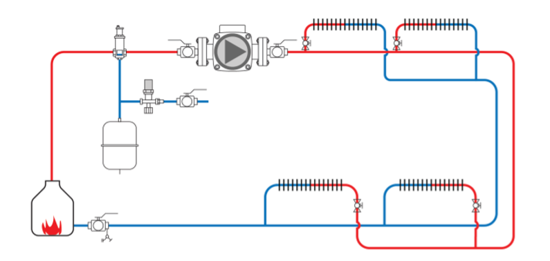
Reverse Return Piping – In a reverse return piping configuration, the supply water is piped to the farthest heat emitter in the circuit first, and then it returns through the remaining heat emitters in reverse order. This helps balance flow rates and offers even heat distribution in multi-zone systems.
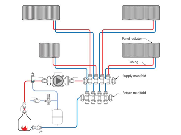
Home Run Piping – Home run piping simplifies distribution by running a separate supply and return line directly to each heat emitter from a central distribution manifold. It offers precise control and is often used in radiant floor heating systems.
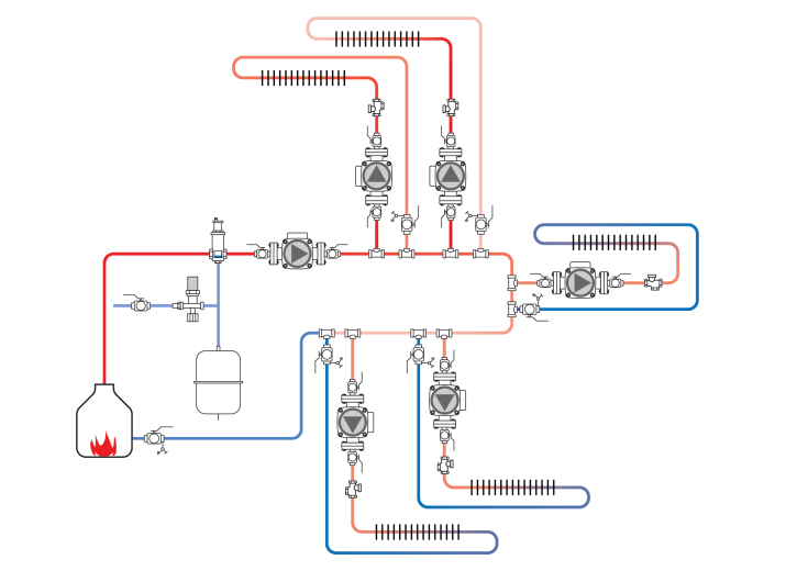
Primary-Secondary Piping (Hydraulic Separation) – Primary-secondary piping separates the primary loop (e.g., boiler loop) from the secondary loops (e.g., zone loops) with a heat exchanger or hydraulic separator. This prevents temperature fluctuations in the primary loop from affecting the secondary loops and allows for efficient operation of multiple zones.
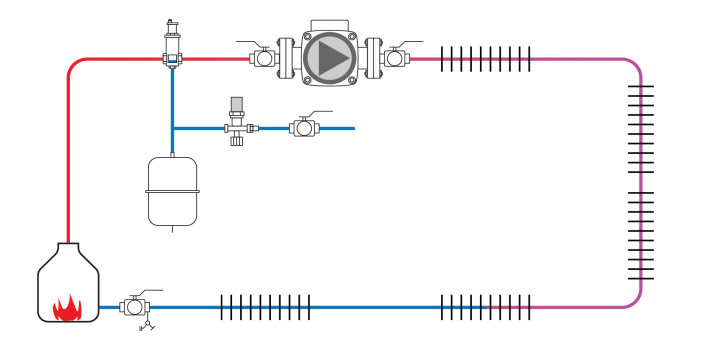
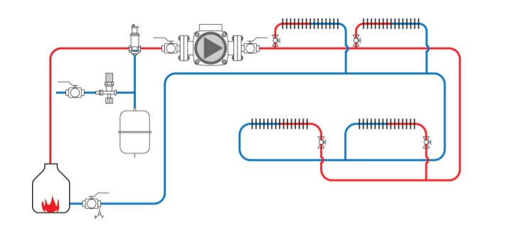
Direct Return Piping – Direct return piping is a straightforward method where the return water from each heat emitter goes directly back to the boiler or heat source. It’s suitable for smaller systems with few zones.
Tree or branch piping is a configuration commonly used in radiant floor heating systems. It involves running supply and return lines from a central manifold to each branch or zone.
In some hydronic systems, such as fan coil units for heating and cooling, two-pipe or four-pipe configurations may be used. Two-pipe systems use the same pipes for both heating and cooling, while four-pipe systems have separate pipes for each.
Air Removal
Air in a hydronic (hot water or chilled water) system can be problematic and have several adverse effects.
Air in the system can form pockets or bubbles that act as insulators, hindering the transfer of heat or cooling. This can lead to reduced system efficiency, uneven heating or cooling, and longer system runtimes, increasing energy consumption and costs. It can accumulate in high points or dead-end sections of the piping, creating airlocks or blockages that impede the flow of water. This can result in reduced circulation, reduced heat delivery to radiators or heat emitters, and potential system overheating or damage.
Air pockets can create noise in the system, causing gurgling, hissing, or banging sounds as water flows past or attempts to displace the air. This noise can be disruptive and annoying, especially in residential settings.
Air can cause pump cavitation, which is the formation of vapor cavities or bubbles in the pump impeller due to reduced pressure. Cavitation can lead to pump damage, reduced pump performance, and increased maintenance costs.
Air can introduce oxygen into the hydronic system. Oxygen, when in contact with metals in the system, can promote corrosion, leading to the deterioration of pipes, radiators, and other components. Corrosion can reduce the system’s lifespan and lead to costly repairs.
Air can also carry contaminants or particulates into the system, which can accumulate in components like valves, pumps, and heat exchangers. This can lead to reduced system performance and clogs.
In heating systems, air can disrupt the even distribution of heat, resulting in cold spots and uneven temperatures within rooms. This can lead to discomfort for occupants.
To address these issues and maintain the optimal performance of a hydronic system, we need to remove air from the system and prevent its reintroduction. This is typically achieved through the following methods:
Regularly bleeding air from high points or air vents within the system helps remove trapped air pockets, installing automatic air elimination devices (air vents or automatic air purgers) in strategic locations within the system can help remove and collect air.
Proper system design that includes air separators, expansion tanks, and purging valves can help minimize air entrainment and promote efficient air removal.
Cross Connection Controls
Cross-connection controls are important safety devices used in hydronic systems to prevent the potential contamination of potable (drinking) water with non-potable water or other substances. In hydronic systems, these controls are primarily employed to safeguard the potable water supply from any backflow or back-siphonage of heating or cooling fluids, chemicals, or contaminants.
Backflow preventers are mechanical devices that prevent the reverse flow of water from a hydronic system into the potable water supply. They come in various types, including double-check valves, reduced pressure backflow assemblies (RP), and vacuum breakers.
Reduced pressure backflow assemblies (RP) are commonly used in hydronic systems. They include two check valves and a relief valve, which is opened when there is a drop in pressure, preventing any backflow into the potable water system.
Air gaps are physical separations between the potable water supply and the hydronic system, achieved by installing a gap or air break between the two systems. An air gap is considered the most reliable method of cross-connection control.
Dual check valves are two independent check valves installed in series to provide a barrier against backflow. They are commonly used in small-scale hydronic systems.
Pressure vacuum breakers (PVBs) are devices used to protect against back-siphonage. They are often installed at the highest point in a hydronic system to provide a barrier against potential contaminants entering the potable water supply.
Atmospheric vacuum breakers (AVBs) are simple, cost-effective devices that prevent back-siphonage. They are typically used in residential and smaller hydronic systems.
Reduced pressure detector assemblies (RPDA) are advanced backflow preventers that not only prevent backflow but also provide monitoring and notification capabilities. They are used in larger, more complex hydronic systems.
Double check detector assemblies (DCDA) are similar to dual check valves but include monitoring capabilities to detect potential backflow events. They are often used in commercial and industrial settings.
The specific type of cross-connection control device used in a hydronic system depends on factors such as system size, complexity, and local plumbing codes and regulations. In many regions, it is a legal requirement to install and maintain cross-connection control devices to protect the potable water supply and maintain public health and safety.
Regular inspection, testing, and maintenance of these devices are needed to make sure the system is functioning correctly and providing the necessary protection. Additionally, cross-connection control devices should be installed by qualified professionals who are knowledgeable about local plumbing codes and regulations.
Make-up Water Line
The makeup water line in a hydronic heating system is a pipe or connection that provides a means for adding fresh water to the system when needed. It serves several important functions.
Over time, hydronic systems may lose water due to evaporation, leaks, or other factors. The makeup water line allows you to replenish the system with water to maintain the proper water level.
Adding makeup water helps maintain the desired pressure within the hydronic system. Adequate pressure is necessary for the proper circulation of the heating or cooling fluid (usually water or a water-glycol mixture) and the efficient operation of components like pumps, boilers, and radiators.
Makeup water can help prevent the buildup of air within the system, which can hinder heat transfer and system performance. By adding water, you can displace any air that may have entered the system.
The makeup water line should be equipped with a backflow preventer to protect the upstream water from any system contamination.

Here’s how the makeup water line typically works in a hydronic system:
The makeup water line is connected to the system at a point where it can safely introduce water into the system, such as near the boiler or expansion tank.
It may include an isolation valve to control the flow of makeup water into the system. This valve can be manually operated or automated.
In some systems, an automatic makeup water valve is used. This valve is equipped with a float or pressure-sensing mechanism that opens when the system pressure drops below a certain setpoint. It automatically adds makeup water to the system as needed to maintain the desired pressure.
Some makeup water systems may incorporate a backflow preventer to ensure that water flows into the system but doesn’t backflow into the potable water supply, preventing contamination.
It’s recommended to monitor and control the makeup water carefully to prevent overfilling the system, which can lead to pressure issues or damage. Systems often have a pressure relief valve that can discharge excess pressure if necessary.
Properly maintaining the makeup water system and monitoring the hydronic system’s water level and pressure are crucial for the safe and efficient operation of the hydronic heating or cooling system. Regular inspections and maintenance, including checking for leaks and ensuring the makeup water line is functioning correctly, are essential to prevent issues and maintain system performance.
 Now complete Self-Test 2 and check your answers.
Self-Test 2
Self-Test 2
Media Attributions
- Figure 2. “Hydronic System” by COD Newsroom on Flickr is licensed under a CC BY 2.0 licence.
- Figure 3. “Energy shut off switch” from DesignAndBuild is used for educational purposes under the basis of fair dealing.
- Figure 4. “Operating or limit aquastat” from Resideo Technologies is used for educational purposes under the basis of fair dealing.
- Figure 5. “Series piping” from SkilledTradesBC is used for educational purposes under the basis of fair dealing.
- Figure 6. “Reverse return piping” from SkilledTradesBC is used for educational purposes under the basis of fair dealing.
- Figure 7. “Home run piping” from SkilledTradesBC is used for educational purposes under the basis of fair dealing.
- Figure 8. “Primary secondary piping” from SkilledTradesBC is used for educational purposes under the basis of fair dealing.
- Figure 9. “Direct return piping” from SkilledTradesBC is used for educational purposes under the basis of fair dealing.
- Figure 10. “Direct return piping indicating make up water line” from SkilledTradesBC is used for educational purposes under the basis of fair dealing.
