Competency F4: Install Hydronic Systems
Learning Task 1
Describe testing procedures for hydronic systems, components, and controls
Safe Work Practices
Safety is no accident. When testing a hydronic system, safe working practices are just as important as with any other task. Testing includes pressurizing pipes, checking electrical connections, and identifying and fixing problems. Each one has inherent dangers and needs to be addressed before work begins.
Lock-out/Tag out
Much equipment used in hydronic systems will need to be safely locked out before testing can be performed. Remember that a lock out procedure is not just electrical, but all potential energy. Make sure pressure is relieved and all components have stopped spinning before performing any tests. When working around others, inform all workers on or near the hydronic system that it will be locked out for testing. Identify all potential energy sources in the hydronic system. These may include electrical power supplies, fuel supplies (e.g., natural gas, oil), and stored thermal energy. Turn off all electrical power supplies to the system, including circuit breakers or disconnect switches that control pumps, controls, and any other electrical components. A water heater may have a dedicated 120V or 240V circuit breaker that should be switched to off. Remember to use appropriate lockout/tagout procedures to secure these switches in the off position.
If the system is powered by natural gas, propane, or oil, shut off the fuel supply to the boiler or furnace. Drain the water or fluid from the hydronic system to relieve residual pressure. Use drain valves or vents to facilitate this process. Close isolation valves on the supply and return lines to isolate the system from other connected components or zones. Potential energy may still be present. bleed valves or vents should be opened to release any remaining pressure in the system. This step will prevent water or fluid from spraying when components are disconnected.
On larger systems use lockout/tagout procedures to physically lock and tag all energy sources and isolation points to prevent accidental re-energization. Each lock should be identified with the name of the person who applied it and the reason for the lockout.Verify that all energy sources are disconnected, and there is no power supply or pressure left in the system.
Codes and Regulations
AHJ
AHJ stands for Authority Having Jurisdiction. AHJ is typically a government agency, department, or official responsible for enforcing and interpreting specific codes, standards, regulations, or laws within a jurisdiction. Here’s a more detailed explanation of the concept:
The term jurisdiction refers to a specific geographical area or administrative division, such as a city, where certain rules and regulations apply. Different jurisdictions may have their own set of codes and standards.
Authority refers to the power or responsibility vested in a particular entity or individual to enforce and oversee compliance with the applicable regulations and codes within that jurisdiction. The role and responsibilities of an AHJ can vary widely depending on the jurisdiction and the specific codes or standards they are tasked with enforcing. AHJ can be consulted for a number of things including: plan review, permit Issuance, inspections, code interpretation, enforcement, safety oversight, environmental regulations, and zoning.
Manufacturers’ Specifications
Before performing any tests, make sure to consult the manufacturer’s specifications to confirm all piping and components are properly installed. All guidelines should be followed so that safety and warranties are maintained.
Inspection Types
Information can be gathered before pressurizing a system. Inspection types such as visual pre-checks, and sensory checks can be used to confirm proper functioning of a hydronic system.
Visual Pre-Check
Examine the entire system, including pipes, fittings, valves, pumps, and heat emitters (radiators, baseboard heaters, etc.), for any signs of water leaks. Moisture, water stains, or puddles around components indicate leaks. Check all connections for tightness and security. Loose fittings or connections can lead to leaks. Look for signs of corrosion on metal components, such as pipes, valves, and radiators. Corroded areas may appear discolored or pitted. Check that insulation on pipes and components is intact and in good condition. Damaged insulation can lead to heat loss and reduced system efficiency. Inspect air vents to confirm they are correctly positioned and functioning.
Sensory
A sensory inspection of a hydronic system involves using senses (sight, touch, and hearing) to detect potential issues or irregularities in the system’s operation. This type of inspection can help identify visible and audible clues that may indicate problems with the system. Touch pipes, radiators, and other heat emitters to check for temperature irregularities. Cold spots or uneven heating may indicate flow or balancing issues. Use a hand or a paper towel to check for moisture around components. Dampness or water accumulation can signal leaks or condensation issues. Pay attention to any unusual sounds coming from the system, such as gurgling, hissing, banging, or whistling. Unusual noises may indicate air or water flow problems, cavitation, or issues with pumps or valves. Listen for the sound of circulating pumps. Pumps should operate smoothly without excessive noise. If unusual or loud noises are heard from a pump, it may require attention. Cavitation has often been described as hearing gravel running through the pump. Air vents may make noise when releasing trapped air.
Pressure
A pressure inspection can yield useful information about the system. Stable pressures indicate that the system is working as it should and there are no leaks. Comparing a system’s current pressure to those at initial installation will confirm the system’s pressure stability. Pressure can be inspected at different points in the system by attaching pressure gauges to valve ports and checking pressure.
Thermal
Like pressure inspections, a thermal inspection can be done to gather information. Scan the entire hydronic system using the thermal camera. Check for uneven heat distribution, cold spots, or temperature variations. Look for signs of blockages, leaks, or temperature differences along the length of the pipes. Inspect the heat source for any hotspots or irregular temperature patterns. Verify that insulation is intact and effective in preventing heat loss or gain.
Tools and Equipment
A pressure gauge is used to measure the system’s water pressure. It helps ensure that the system pressure falls within the recommended operating range. A thermometer is used to measure the water temperature within the hydronic system. It’s crucial for verifying that the system is delivering the desired heating or cooling temperature. An infrared thermometer allows for quick measuring of the temperature of pipes, radiators, or terminal units without direct contact. This can be useful for spot-checking temperatures in different parts of the system. A flow meter measures the flow rate of water within the system. It helps ensure that the flow rate matches the design specifications and can be crucial for system balancing.
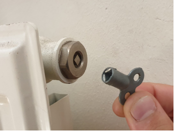
If the system includes a boiler, a combustion analyzer is essential for monitoring combustion efficiency and emissions. It measures parameters like oxygen and carbon monoxide levels in flue gases. If the hydronic system is a chilled water system or uses refrigerant for cooling, a manifold gauge set is used to measure refrigerant pressures and temperatures. It helps diagnose and troubleshoot cooling issues. A multimeter is a versatile tool for measuring electrical voltage and resistance. It can be used to check electrical connections, circuits, and components within the system. This gauge is useful for measuring the pressure drop across filters, strainers, or other components in the system. It helps identify potential flow restrictions. If the system includes a circulation pump, equipment may be needed to test the pump’s performance, such as a flow meter, pressure gauge, and power meter to measure energy consumption. Bleed keys (Figure 1) are used to open bleed valves on radiators or terminal units to release trapped air from the system.
Don’t forget to have a bucket or container on hand to collect water when bleeding air from the system. Towels or rags are useful for cleaning up any spills. Depending on the specific tasks involved, use safety gear such as gloves, safety glasses, or hearing protection.
Test Medium
Fluid
Water testing will locate leaks in the system. A visual inspection for leaks can be done and any leaks fixed before the system is put into operation. If the system will be exposed to freezing temperatures, make sure to use an antifreeze such as glycol for a fluid test.
Compressed Air
Air testing will also expose leaks in the system. By filling with air, leaks can be detected with the use of soapy water, and the risk of water damage is eliminated. Compressed air does create moisture and if the pipes and components are exposed to freezing temperatures, damage could occur.
Inert Gases
When it is not possible to test using air or water, an inert gas can be used. When temperatures drop below freezing, there is a risk that the moisture from air or a fluid testing medium will freeze, expand, and damage the piping and components. If the equipment may be subject to freezing, inert gases such as nitrogen or argon are common choices. This testing procedure would be performed the same as a compressed air pressure test, however, instead of air, a cylinder of the inert gas would be connected to the system and used to fill the pipes to the desired pressure.
Procedures
Filling
Before beginning, check that the system is completely shut down and that all electrical power to pumps, boilers, and other components is turned off. Identify the drain and fill points on the hydronic system. These are typically located at the lowest point in the system for draining and at a convenient point for filling. Use clean, deionized water or a water/antifreeze mixture suitable for the climate and system requirements. Make sure the water is at room temperature. Close any isolation valves on the system that may be open. This includes zone valves, isolation valves on the boiler or heat source, and any other open valves in the system. If there is a drain point, connect a hose to it and place the other end in a suitable drainage area or container. Open the drain valve slowly to allow air to enter the system, which helps with draining. Allow the water to drain completely from the system. Open bleed valves on radiators or other high points in the system to aid drainage. Once the system is drained, close the drain valve.
To fill, connect a hose to the fill point, ensuring that it is secure. Open the fill valve or connection slowly to allow water to enter the system. Monitor pressure gauges. As the system fills with water, bleed air from high points in the system. Open bleed valves or bleed screws on radiators or terminal units until water flows steadily. Continue filling until the system is pressurized to the recommended level. Inspect the system for any leaks during and after filling. Check all connections, valves, and joints. Once the system is filled and all air is purged, close the fill valve. Check the system pressure and make sure it remains within the recommended operating range.
Draining
Identify the drain points on the system, located at the lowest points. If available, attach a hose to the drain valve and place the other end in a suitable drainage area. Slowly open the drain valve to allow water to drain from the system. Open bleed valves at high points to aid in draining and release air locks. Once the system is drained, close the drain valve securely. Open bleed valves or bleed screws on radiators or terminal units to release any remaining air in the system. After draining, inspect the system for any issues and perform any necessary maintenance or repairs before refilling.
Purging
Purging a hydronic heating or cooling system is a crucial step to remove air or gas pockets that can reduce the system’s efficiency and heating/cooling performance. Air in the system can lead to reduced heat transfer, noisy operation, and potential damage to system components. Locate the air vents or purge valves in the hydronic system. These are typically located at high points in the system, such as on radiators, baseboards, or near the top of piping loops. Confirm that the system pressure is within the recommended operating range. If it’s too low, add water to the system through the fill valve until it reaches the proper pressure. If the system has automatic air vents, they should release air on their own when the system operates. Monitor these vents for signs of air being purged, such as air bubbles or water droplets. If an automatic vent is not functioning correctly, it may need to be replaced or serviced.
If the system has manual air vents, use a screwdriver or bleed key to slowly open the vent. Air will escape, followed by water. Be prepared to collect the purged water. The water may be discolored initially as air is purged, but it should become clear once all the air is removed. Close the manual vent once water flows steadily without air bubbles. Go to each air vent or purge valve in the system and repeat the process until all air is purged. After purging air, check the system pressure again to confirm it’s within the recommended range. Adjust if necessary. Inspect the system for any signs of leaks, especially around the manual air vents that were opened. Tighten any connections if necessary. Turn the system back on and allow it to operate normally. Monitor the system for any unusual noises or performance issues. Proper purging should result in improved heating/cooling performance and reduced noise.
Return to Service
Before returning a system to service, make sure to inform any workers in the area. Inform the occupants or building managers when needed.
Documentation
Keep records of any issues or observed irregularities during inspection and testing. This information can be helpful for troubleshooting and maintenance. Documenting the testing process provides a clear record of the activities performed, verifies compliance with regulations, and serves as a reference for future maintenance or troubleshooting. It is important to follow any specific documentation requirements or guidelines provided by local authorities, regulatory bodies, or industry standards when commissioning fixtures and appliances.
 Now complete Self-Test 1 and check your answers.
Self-Test 1
Self-Test 1
Media Attributions
- Figure 1. “Radiator bleed key“ by Sil10napel from Wikimedia Commons is licensed under a CC BY-SA 4.0 licence.
