- 2-3 Holding Contact
Also known as a "maintaining" contact, these are the normally open contacts of a magnetic starter that are connected in parallel with the start button in a three-wire control circuit. When using the conventional NEMA numbering system, they get wire numbers "2" and "3."
- Ammeter
A device used for measuring the value of current flowing through a circuit. The ammeter has a very small internal resistance and so must be connected in series with the circuit to prevent dangerous levels of current from flowing.
Can be digital or analogue and measure either AC or DC.
- Ampere (A)
The unit used to measure electrical current. It is equal to a flow of one coulomb per second. It may also be called "amp."
- Anti-Plugging Circuit
A circuit that is not designed to suddenly stop or reverse a motor until the shaft has come to a rest.
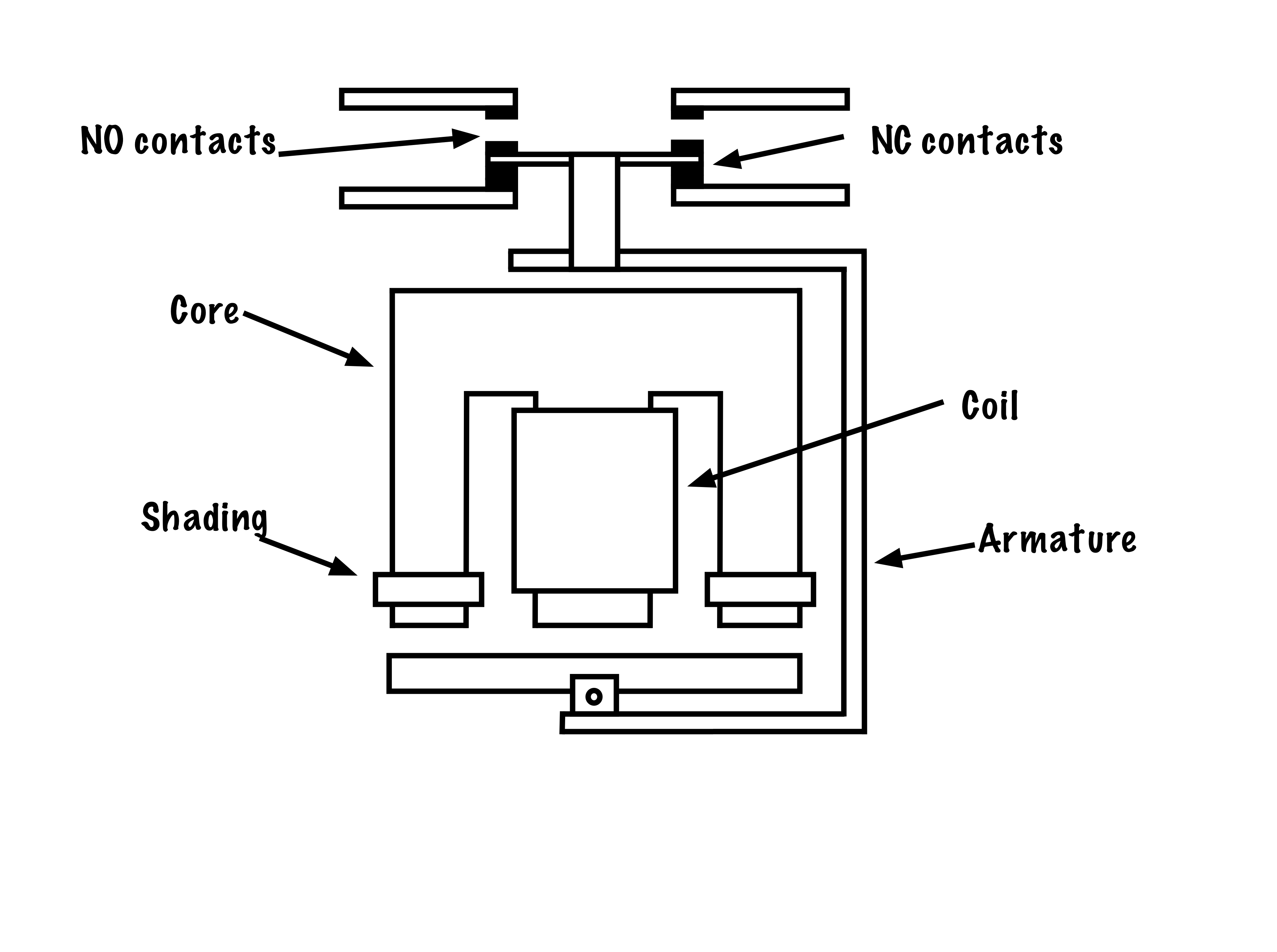
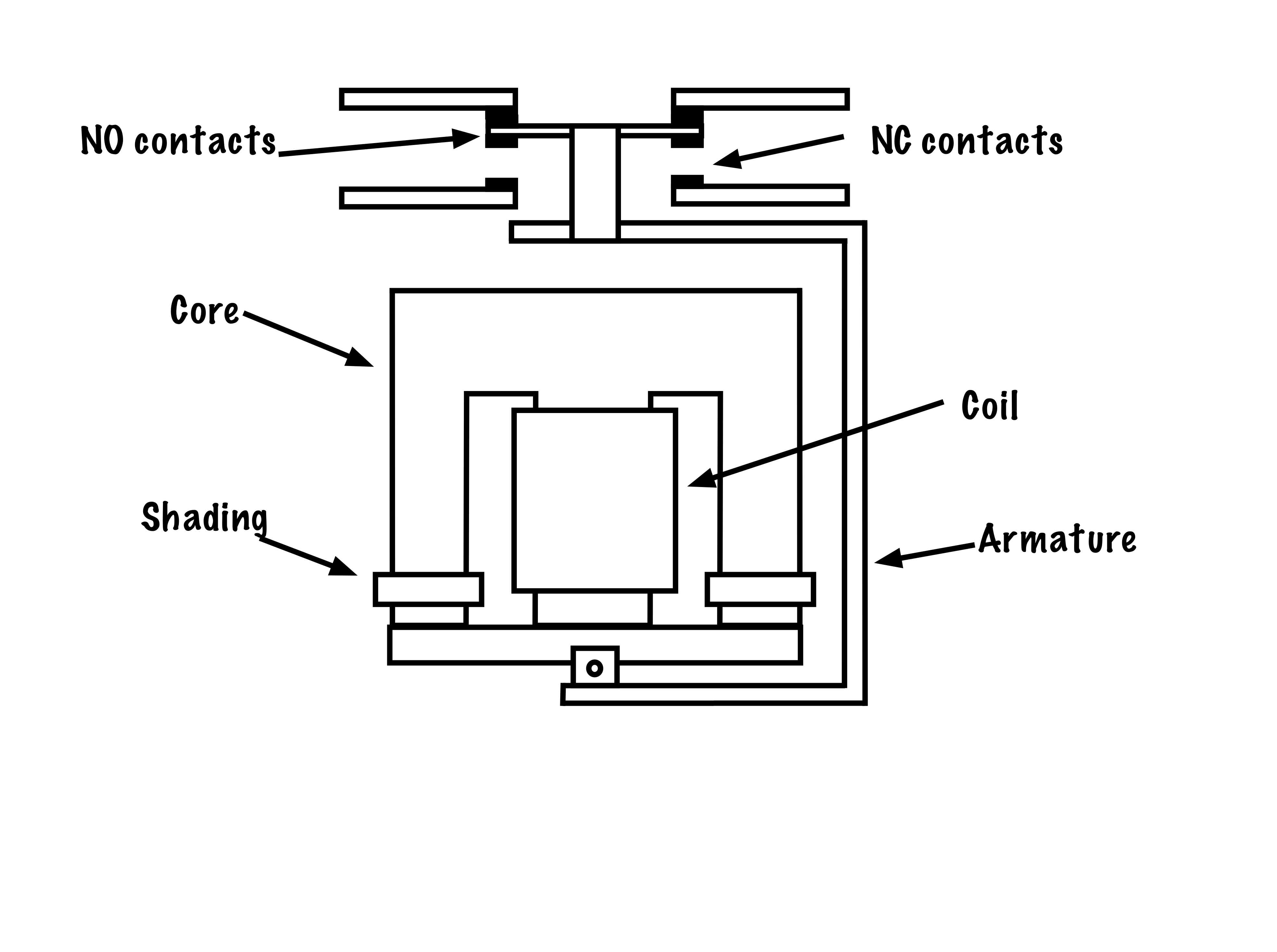
- Armature
With respect to magnetic contactors, the armature or plunger is the movable part of the magnetic circuit. When a coil is energized the armature is pulled in, opening and/or closing a set or sets of contacts.
- Auxiliary Contacts
Contacts on a magnetic starter that are not Horsepower rated. Can come as either normally-open or normally-closed and can be used as maintaining contacts, electrical interlocks or control for pilot lights.
- Circuit Breaker
An automatic device that is designed to safely disconnect circuits under fault conditions. Most circuit breakers provide Overload and Overcurrent protection, and are rated in Volts, Amps and Horsepower.
- Circuit Diagram
A diagram that uses lines and symbols to show the electrical continuity and connections of a circuit. Can be used either for troubleshooting (schematic diagrams) or connection purposes (wiring diagrams).
- Contact
The conducting part of a switch that makes or breaks a circuit.
- Continuous-Duty Rating
The maximum rated value of RMS current that the overcurrent device is designed to handle on a continuous basis without tripping.
- Control Circuit
In contrast to the Power Circuit, the Control Circuit consists of inputs, in the form of switches, pushbuttons or pilot devices, which when activated, can either directly, or through a magnetic motor starter, energize a load. The Control Circuit often operates at a lower voltage than the Power Circuit for safety and ease of installation.
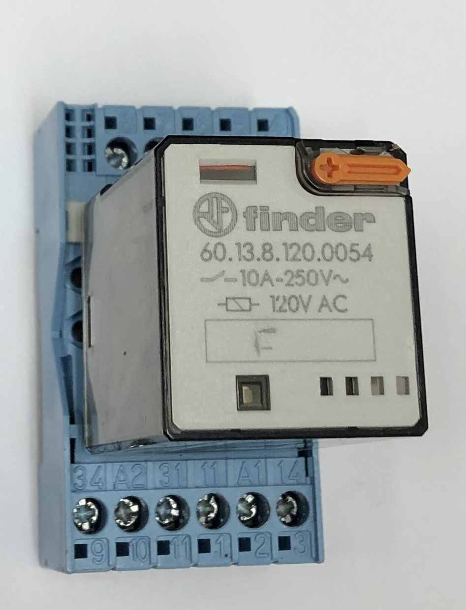
- Control Relay
Used when additional auxiliary contacts are needed in a control circuit, a control relay is a magnetic contactor which is not designed for the energization of motors, and does not have built in overload protection.
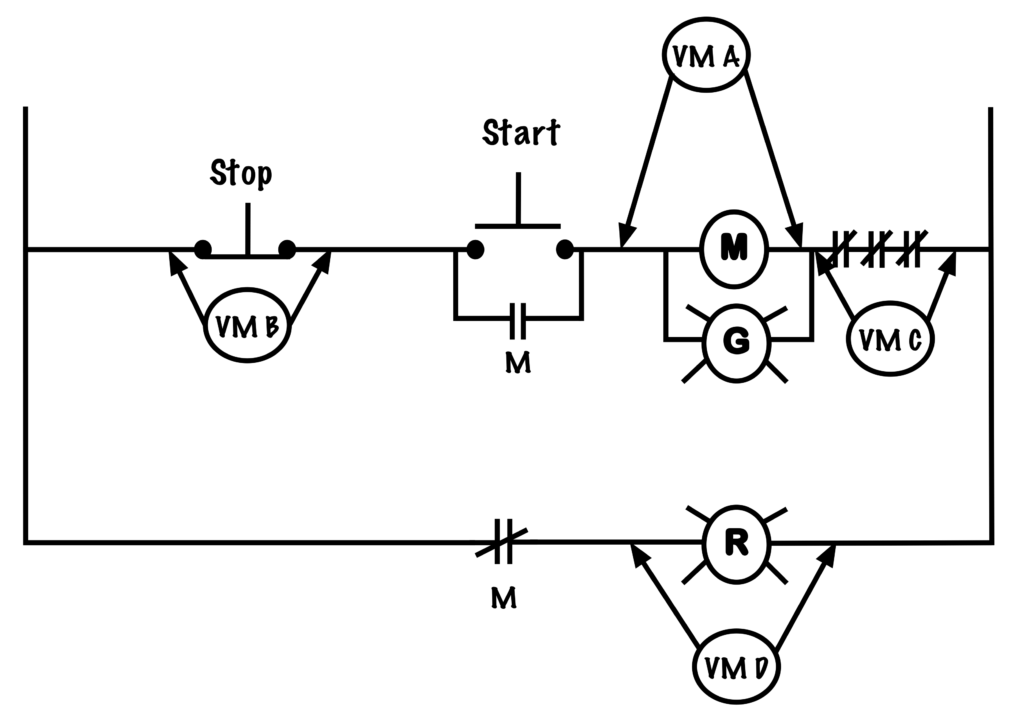
- Crisscross Voltmeter Method
The crisscross voltmeter method is used to troubleshoot fuses on a live circuit. It involves checking the potential difference between the line and load sides of fuses connected to different phases in a three-phase fusible disconnect.
- Current (I)
The rate of flow of an electric charge, measured in amperes (or amps). When one coulomb of charge moves past one point in once second, current is said to flow at a rate of one ampere. Current flows from negative potential to a positive potential through a load.
- Electrical Interlock
Normally-closed contacts used in forward/reverse control circuits that prevent both directions coils from being energized at the same time.
- Electrically Common
Referring to two or more points in a circuit which have no loads or switches between them and have no potential difference between them.
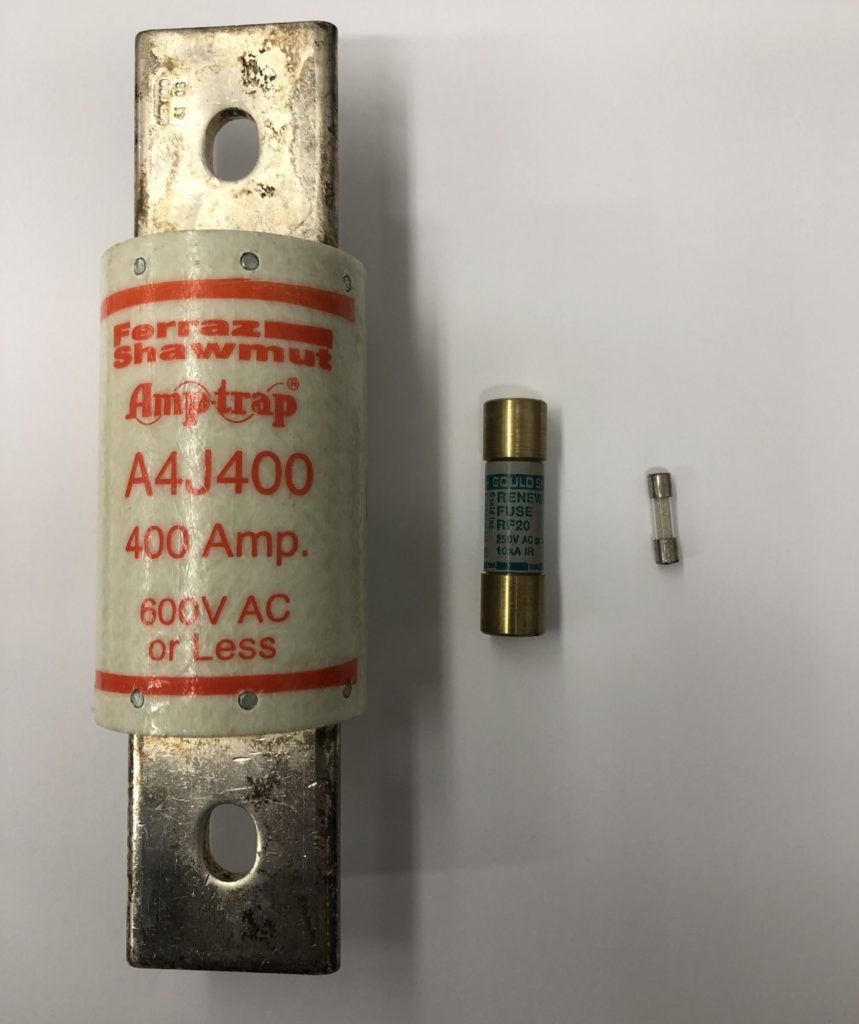
- Fuse
An insulated tube containing a strip of conductive metal that has a lower melting point than either copper or aluminum. It protects a circuit from damage because it will melt in overload or overcurrent situations and break the connection with the rest of the circuit.
- Horsepower-Rated Contact
A set of contacts that has been designed to make or break the flow of current to a motor and can handle loads up to a specified amount of horsepower at a specific voltage. The size of contacts are determined by the size of the motor they are controlling.
- Inching
The term given to the momentary energization, at reduced voltage, of a motor only so long as an operator is pressing a button.
- Inrush Current
The initial high value of current produced when an inductive load is first energized.
- Interrupting-Capacity (IC) Rating
The maximum fault current that an overcurrent device can interrupt without damage to itself. Most circuit breakers and fuses have an IC rating of 10,000 amps.
- Isolating Switch
A switch that is used to lockout an electrical circuit once a motor has been turned off to ensure it is completely de-energized. Not designed to interrupt the flow of current.
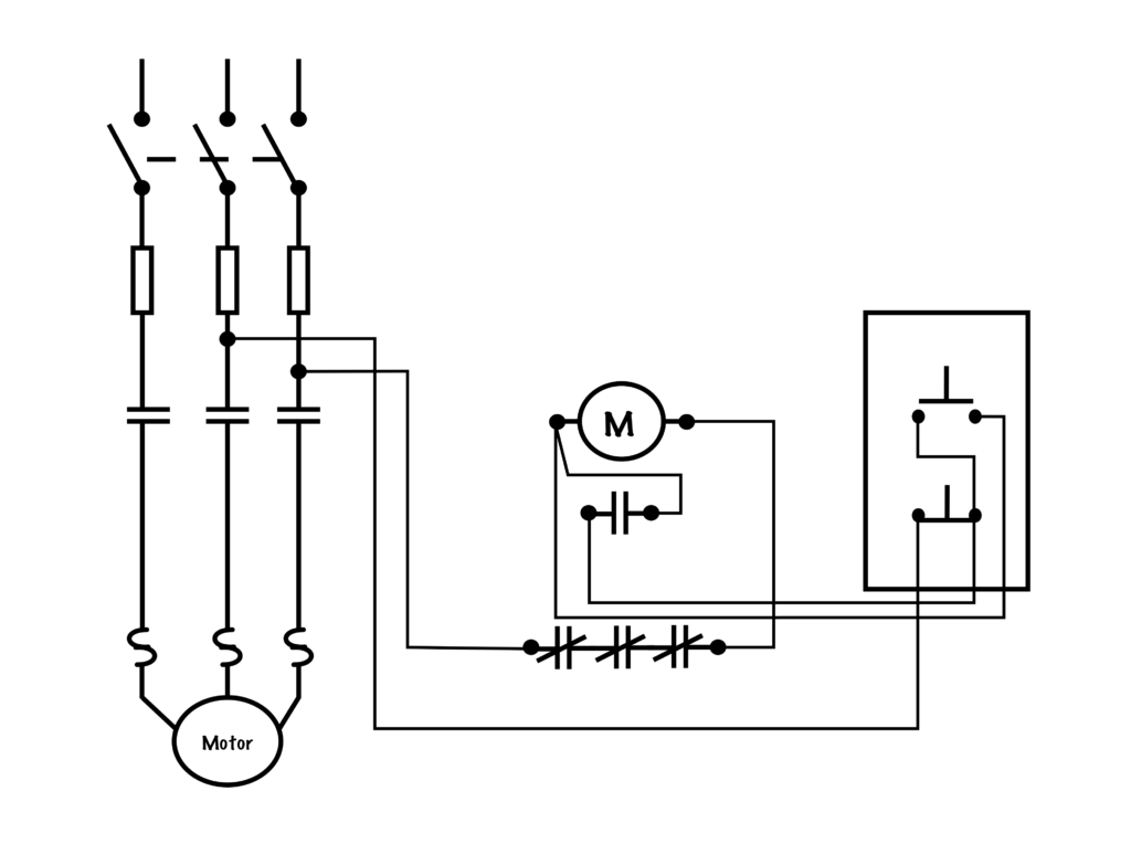
- Jog Circuit
A control circuit that allows an operator to either start the motor or “Jog” the motor only so long as a pushbutton is depressed, and are commonly used for motors controlling conveyor belts to allow for precise positioning of materials.
- Jogging
The term given to the momentary energization, at full voltage, of a motor only so long as an operator is pressing a button.
- Kirchhoff’s Current Law
"The sum of the currents entering a point must equal the sum of the currents exiting that point."
In a series circuit the same value of current flows through each device and the source.
I total = I1 = I2 = I3...
In a parallel circuit, each individual branch will contribute its current to the total current.
I total = I1+ I2 + I3...
- Kirchhoff’s Voltage Law
"The sum of the voltage rises must equal the sum of the voltage drops in a circuit."
In a series circuit, the total voltage at the source is equal to each of the individual voltage drops in any loads.
E total = E1 + E2 +E3...
Loads connected in a parallel circuit will experience the same potential difference.
E total = E1 = E2 = E3...
- Ladder Diagram
See Schematic Diagram.
- Locked-Rotor Current
The current drawn by a motor when the motor is not spinning.
- Lockout Relay
A special solenoid coil included in a plugging switch assembly that disables the contacts until the motor itself has been energized.
- Low-Voltage Protection (LVP)
Circuits with low-voltage protection will not automatically turn back on when voltage is restored following a power outage. Examples include the microwave or power tools.
- Low-Voltage Release (LVR)
Circuits with low-voltage release are designed to re-energize automatically when voltage is restored after a power outage. Examples include lights or the kitchen fridge.
- Mechanical Interlock
A physical barrier that is pushed into the path of one coil's armature by the movement of the adjacent coil in a forward/reversing motor starter.
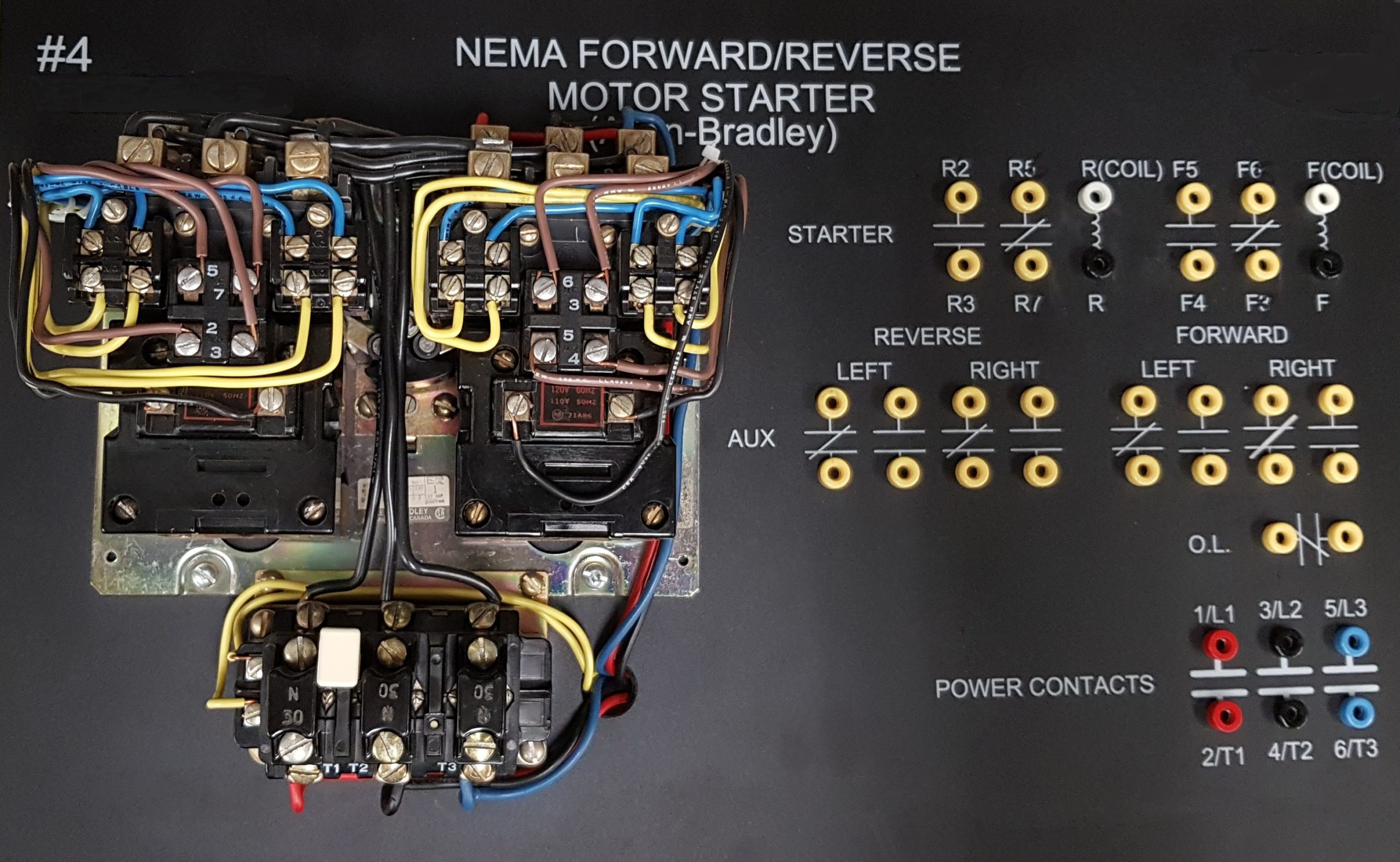
- Motor Starter
A device that controls the flow of electrical power to a motor. It is designed to safely start and stop a motor, and provide overload protection.
- Normally-Closed (NC) Contact
A contact that under normal conditions has continuity through it. When the contact changes its state it interrupts the flow of current by opening its contacts. Can be associated with pushbuttons, pilot devices or magnetic contactors.
- Normally-Open (NO) Contact
A contact that under normal conditions does not have continuity through it. When the contact changes its state it permits the flow of current by closing its contacts. Can be associated with pushbuttons, pilot devices or magnetic contactors.
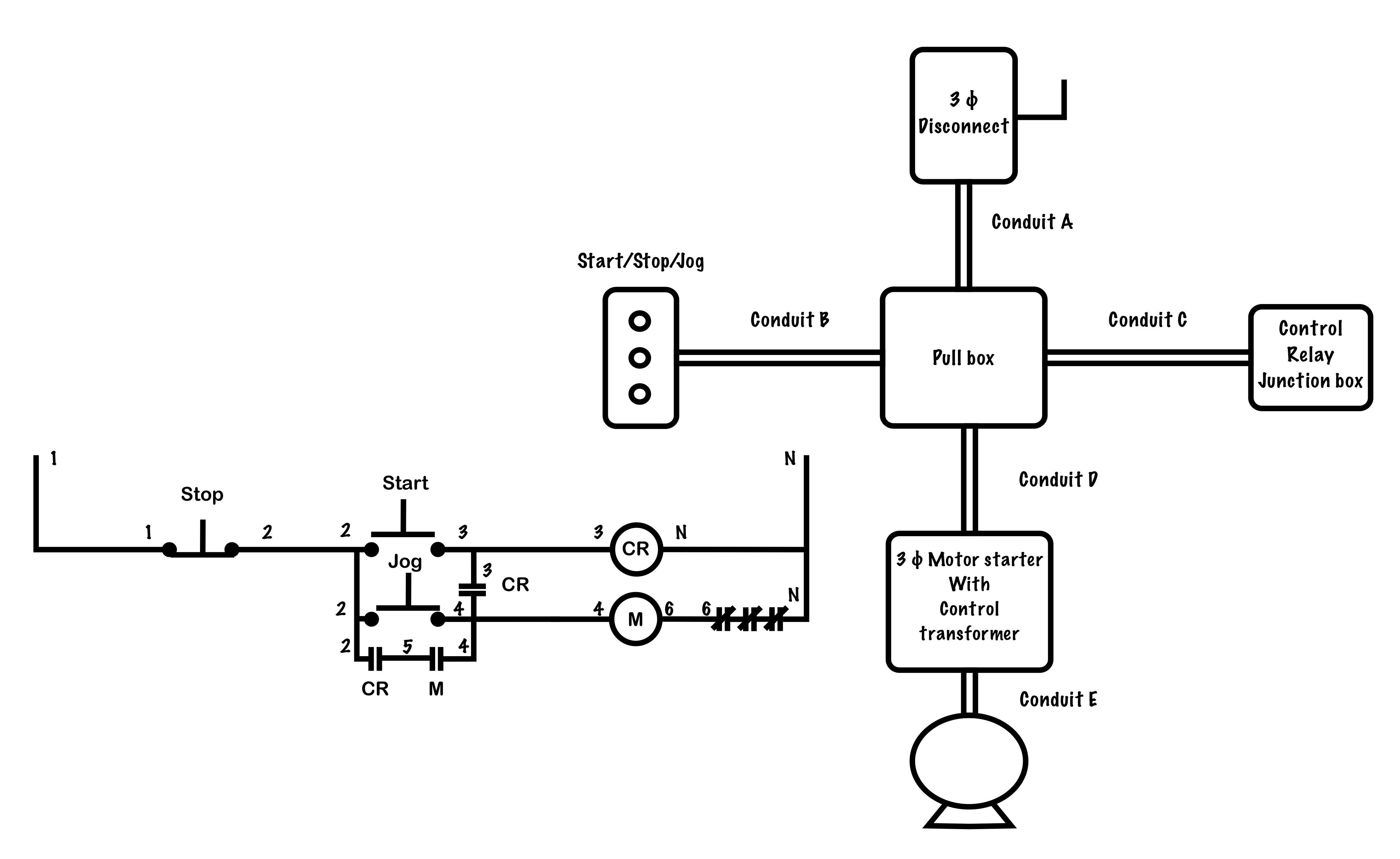
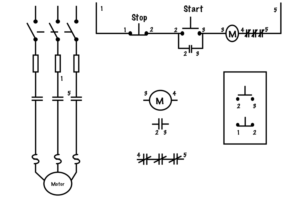
- Numbering System
Used to convert between wiring and schematic diagrams, the numbering system is a method of identifying and labelling each electrically common point in a circuit. Two wires are considered electrically common if they share an electrical connection with no switches or loads between them, and so would be assigned the same number in the diagram.
- Ohm
The unit used to measure electrical resistance (Ω). It takes one volt to push one amp through one ohm of resistance.
- Ohm’s law
Current = Voltage divided by Resistance (or I=E/R).
- Ohmmeter
A device used to measure the resistance of a circuit. Ohmmeters must not be used on live circuits. Ohmmeters connect a small internal voltage source to the circuit that is being measured or tested, and determine the value of resistance or continuity by measuring what value of current flows through the meter.
Can be either digital or analogue.
- Overcurrent
A sharp and fast rise in current over a short period of time (fractions of a second) where the value of current is far greater than the nominal line current.
- Overload
A moderate and gradual rise in the value of current over a relatively long period of time that is caused by excessive amounts of current drawn by a motor due to too much load being put on the motor.
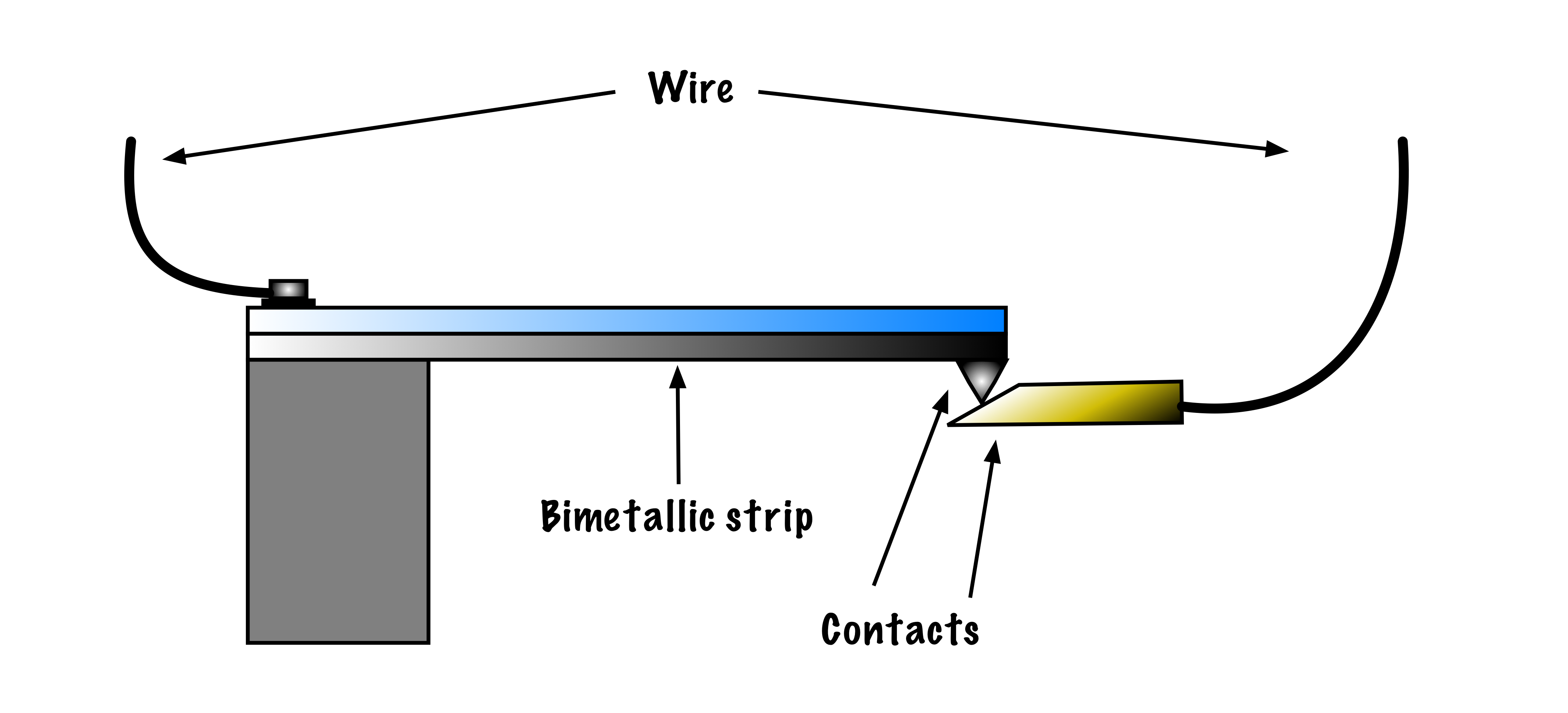
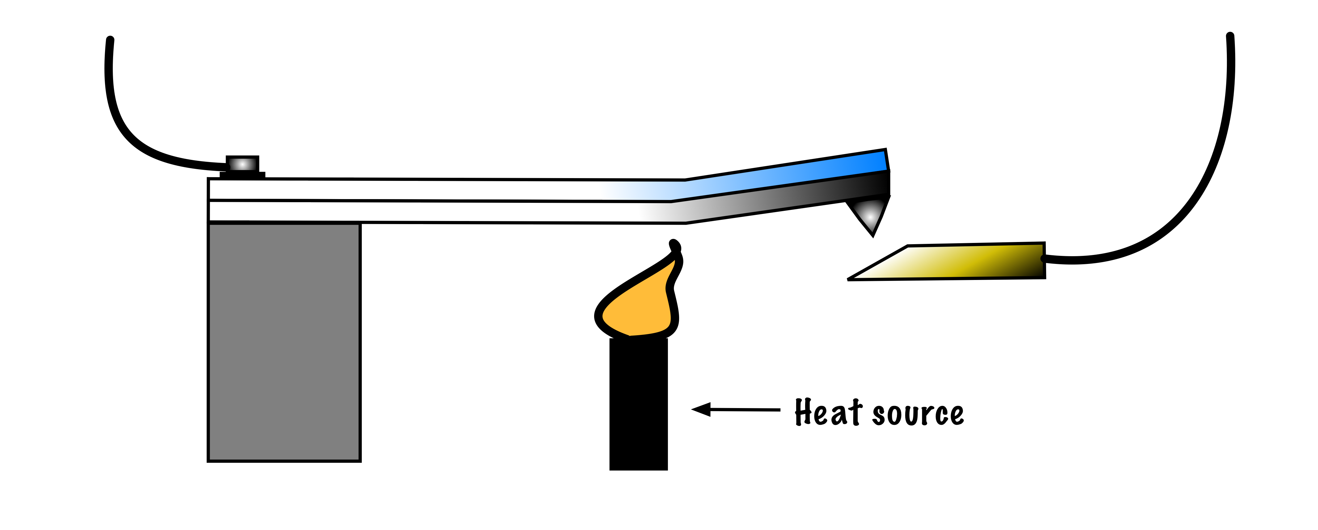
- Overload Relay (OLR)
A heater element paired with normally-closed contacts that open once the heater gets too hot. Two types of relays are the bimetallic strip and the melting solder pot.
- Parallel
In electrical terms, refers to a connection where current has more than one path to flow.
Loads connected in parallel will experience the same potential difference (voltage), but may draw different values of current depending upon their individual resistance.
- Phase Rotation
The direction that a three-phase motor spins is determined by the phase sequence of the voltage impressed upon it. To reverse the direction of the motor we simple reverse the phase sequence by switching any to line leads.
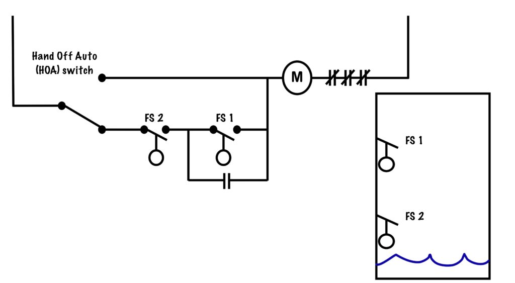
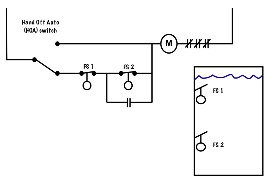
- Pilot Device
An auxilary device that provides indication or control of a process to an operator. Pilot devices include automatic switches such as float and pressure switches, as well as indicating lights.
- Pilot Light
A small lamp connected in the control circuit to indicate the status of a motor or other situation.
- Plugging
When a motor is spinning in one direction and is stopped and suddenly re-energized in the opposite direction before the shaft of the motor has time to come to a complete stop.
- Plugging Circuit
A circuit that utilizes the momentary reversal of the direction of a three-phase motor to bring it to a sudden stop. Can be very hard on the motor and any driven equipment.
- Power
The rate at which work is done. It is measured in watts (W), or joules per second (J/s).
- Power Circuit
In contrast to the control circuit, the power circuit provides the large values of voltage and current used by the motor itself. Must be equipped with overcurrent and overload protection, and horsepower-rated contacts in the control gear equal to the voltage and current ratings of the motor.
- Process Variable
A measured value of a particular part of a process that is being monitored or controlled, such as temperature, pressure, liquid level, flow, position or proximity.
- Pushbutton
A momentary contact device that has a built in spring to return the button to its normal position once release. Available with either normally-open, normally-closed or both sets of contacts.
- Resistance (R)
The opposition to the flow of current in an electric circuit, measured in ohms (Ω).
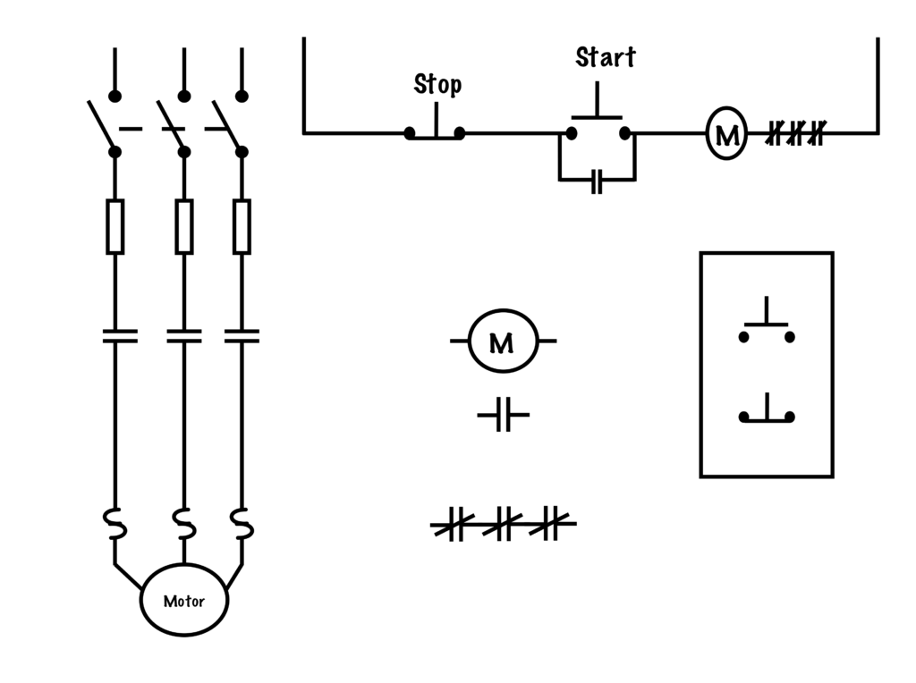
- Schematic Diagram
A diagram that shows how a circuit works logically and electrically. It uses symbols to identify components and interconnecting lines to display the electrical continuity of a circuit. It is often used for troubleshooting purposes. Also known as a ladder diagram.
- Series
In electrical terms, refers to a connection where current has only one path to flow.
Loads connected in series will have the the same value of current flowing through them, and share the total voltage between them. Switches and overcurrent equipment is connected in series with equipment to control and protect it.
- Single-Phase System
The simplest electrical circuit. It requires only two lines: one for power to go in and the other is a return path for current. These are often called Line 1 and Line 2, or Line 1 and Neutral. Current only has one path to travel in a single-phase circuit, such as a control circuit.
- Switch
A device for making or breaking the connection in an electric circuit.
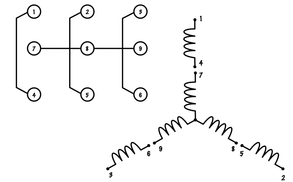
- Three-Phase System
An electrical circuit that uses three current carrying conductors, called Line 1, Line 2, and Line 3, which have a 120° phase shift in the voltage and current waveforms between them. The Power Circuit of three-phase motors is an example of a three-phase circuit.
- Three-Wire Circuit
In motor control terminology, a three-wire circuit utilizes a magnetic motor starter with a holding contact, along with momentary contact pushbuttons. A three-wire circuit provides low-voltage-protection.
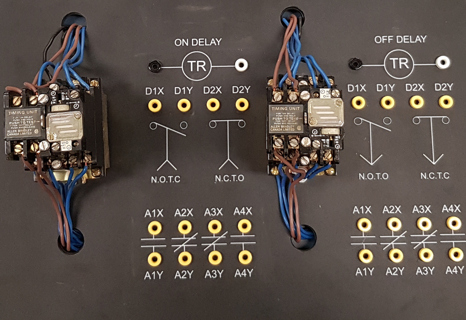
- Time-Delay Relay
A control relay equipped with a delay mechanism that can be used to alter the timing effects of a set of contacts. There are two varieties of timer relays: On-delays which have their delay action when they are energized and revert to their original condition instantly upon de-energization, and off-delays, which change the state of their contacts instantly upon energization, but have a delay before reverting to their normal condition upon de-energization.
- Two-Wire Circuit
In motor control terminology, a two-wire circuit utilizes a manual motor starter with a maintained contact. A two-wire circuit provides low-voltage release.
- Voltage (E)
The difference in electric potential between two points, which is defined as the work needed per unit of charge to move a test charge between the two points. It is measured in volts (V).
- Voltage Rating
The maximum amount of voltage that a fuse, circuit breaker, switch-gear or motor starter can handle. The voltage rating of a fuse or circuit breaker must be equal to or greater than the system voltage.
- Voltmeter
A device testing and measuring the potential difference (voltage) between two points. Leads are connected in parallel with the circuit, and the meters very high internal resistance will draw a small current which can be used to determine the level of voltage.
Can be digital or analogue and measure either AC or DC.
- Watt (W)
The unit used to measure power in an electric circuit, equivalent to one joule per second, or the power dissipated when one volt pushes one amp through a circuit.
- Watt’s law
Power = Voltage times Current (or W=EI)
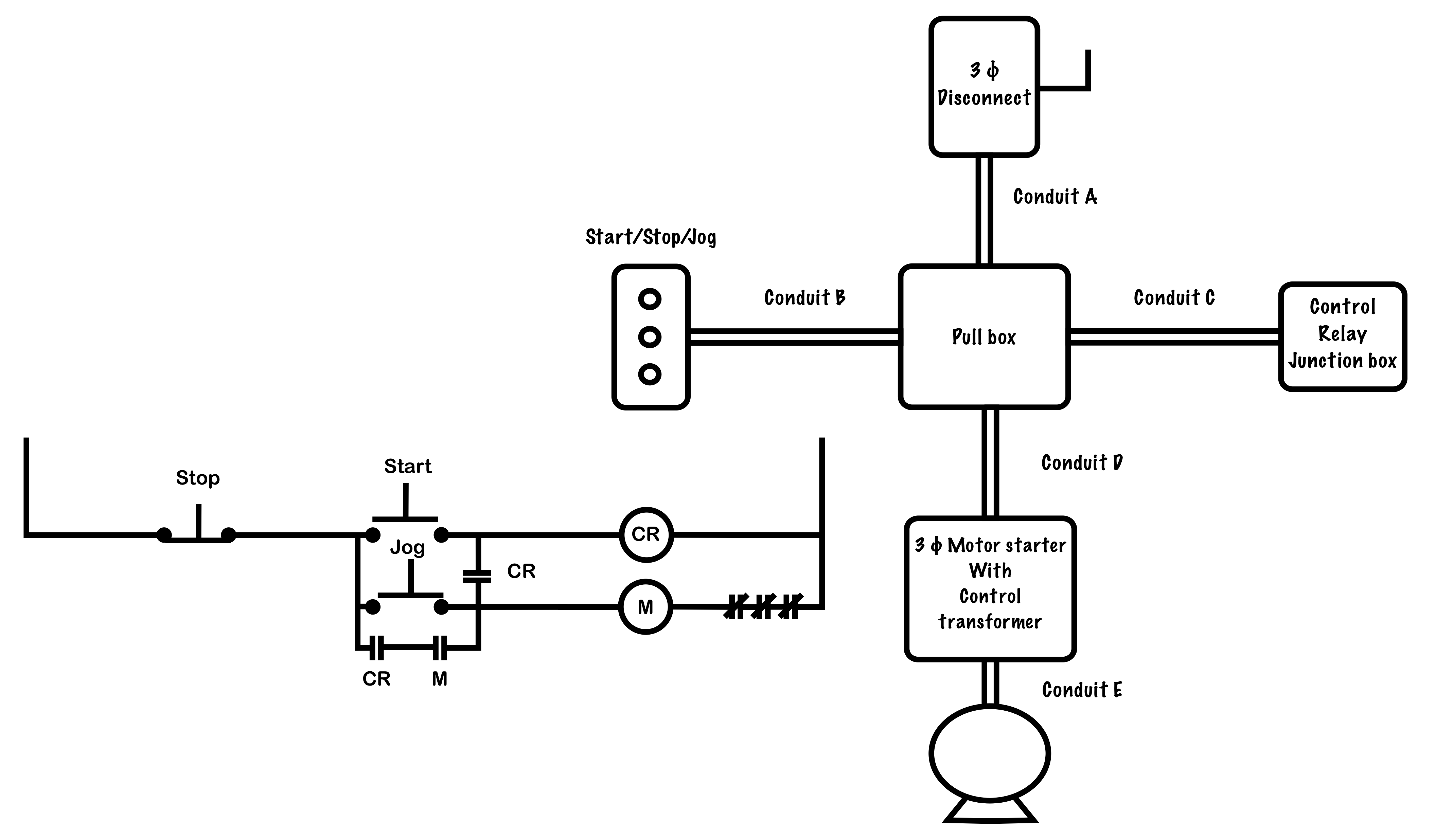
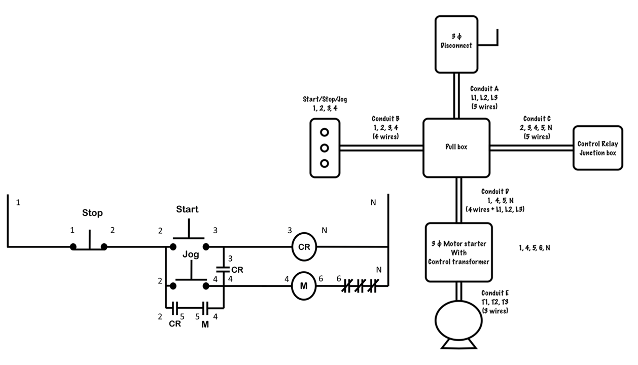
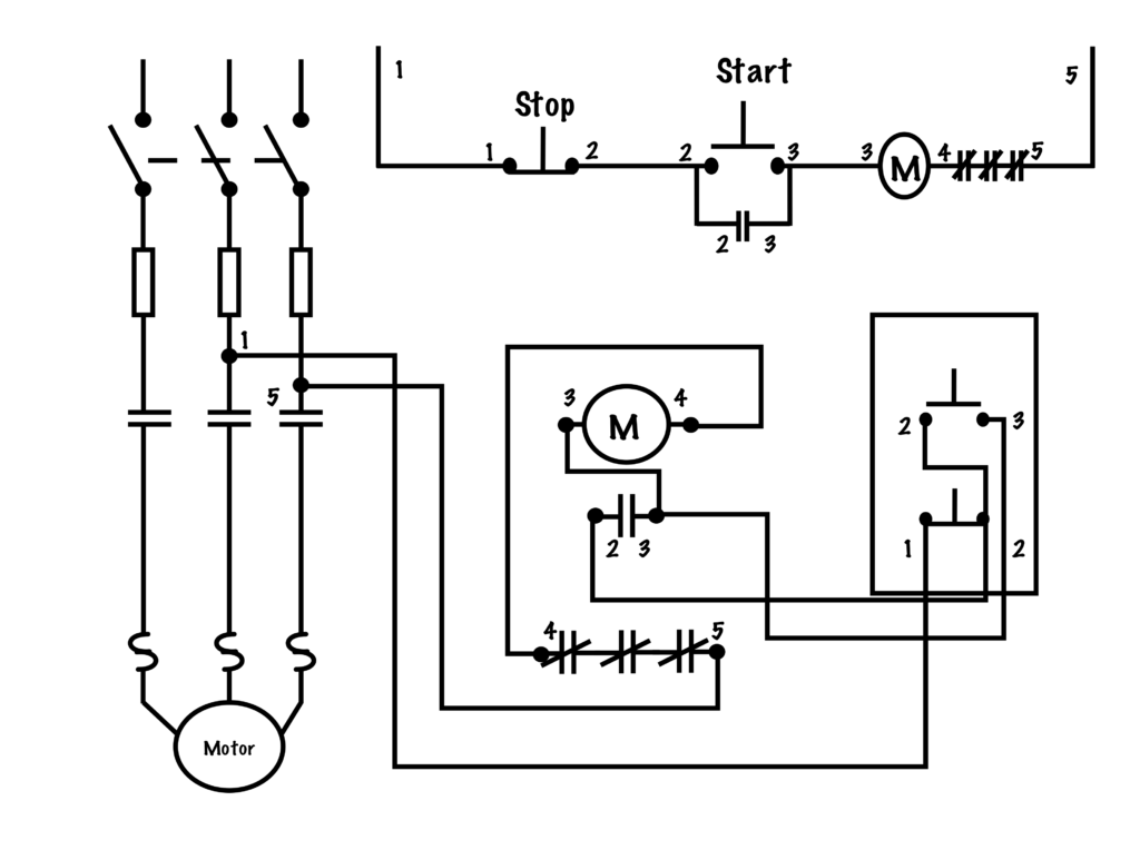
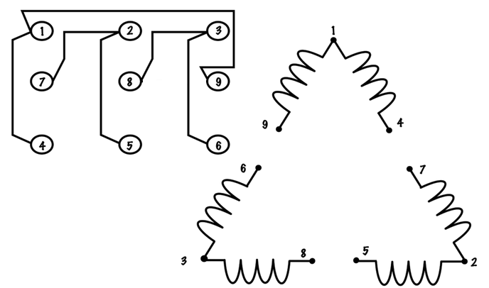
- Wiring Diagram
A diagram shows how equipment is laid out and the connections between them. This type of diagram shows the physical relation of all devices in the system, the conductor terminations between these devices, and are commonly used in motor control installations. Also known as a connection diagram.
- Zero-Speed Switch
A switch that is activated by centrifugal forces and is attached either directly or via a belt to the shaft of the motor.


 A zero-speed switch is a switch that is activated by centrifugal forces and is attached either directly or via a belt to the shaft of the motor. To provide


 This circuit utilizes two off-delay coils to prevent the forward and reverse coils from being energized until ten seconds after the stop button has been pressed. This will give the shaft of the motor time to wind down to a halt and provide an anti-plugging feature for the circuit. To achieve this, the normal