Main Body
Chapter 9 Integrity Rules and Constraints
Adrienne Watt & Nelson Eng
Constraints are a very important feature in a relational model. In fact, the relational model supports the well-defined theory of constraints on attributes or tables. Constraints are useful because they allow a designer to specify the semantics of data in the database. Constraints are the rules that force DBMSs to check that data satisfies the semantics.
Domain Integrity
Domain restricts the values of attributes in the relation and is a constraint of the relational model. However, there are real-world semantics for data that cannot be specified if used only with domain constraints. We need more specific ways to state what data values are or are not allowed and which format is suitable for an attribute. For example, the Employee ID (EID) must be unique or the employee Birthdate is in the range [Jan 1, 1950, Jan 1, 2000]. Such information is provided in logical statements called integrity constraints.
There are several kinds of integrity constraints, described below.
Entity integrity
To ensure entity integrity, it is required that every table have a primary key. Neither the PK nor any part of it can contain null values. This is because null values for the primary key mean we cannot identify some rows. For example, in the EMPLOYEE table, Phone cannot be a primary key since some people may not have a telephone.
Referential integrity
Referential integrity requires that a foreign key must have a matching primary key or it must be null. This constraint is specified between two tables (parent and child); it maintains the correspondence between rows in these tables. It means the reference from a row in one table to another table must be valid.
Examples of referential integrity constraint in the Customer/Order database of the Company:
- Customer(CustID, CustName)
- Order(OrderID, CustID, OrderDate)
To ensure that there are no orphan records, we need to enforce referential integrity. An orphan record is one whose foreign key FK value is not found in the corresponding entity – the entity where the PK is located. Recall that a typical join is between a PK and FK.
The referential integrity constraint states that the customer ID (CustID) in the Order table must match a valid CustID in the Customer table. Most relational databases have declarative referential integrity. In other words, when the tables are created the referential integrity constraints are set up.
Here is another example from a Course/Class database:
- Course(CrsCode, DeptCode, Description)
- Class(CrsCode, Section, ClassTime)
The referential integrity constraint states that CrsCode in the Class table must match a valid CrsCode in the Course table. In this situation, it’s not enough that the CrsCode and Section in the Class table make up the PK, we must also enforce referential integrity.
When setting up referential integrity it is important that the PK and FK have the same data types and come from the same domain, otherwise the relational database management system (RDBMS) will not allow the join. RDBMS is a popular database system that is based on the relational model introduced by E. F. Codd of IBM’s San Jose Research Laboratory. Relational database systems are easier to use and understand than other database systems.
Referential integrity in Microsoft Access
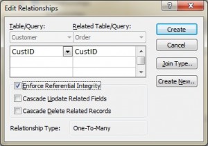
In Microsoft (MS) Access, referential integrity is set up by joining the PK in the Customer table to the CustID in the Order table. See Figure 9.1 for a view of how this is done on the Edit Relationships screen in MS Access.
Referential integrity using Transact-SQL (MS SQL Server)
When using Transact-SQL, the referential integrity is set when creating the Order table with the FK. Listed below are the statements showing the FK in the Order table referencing the PK in the Customer table.
( CustID INTEGER PRIMARY KEY,
CustName CHAR(35) )
( OrderID INTEGER PRIMARY KEY,
CustID INTEGER REFERENCES Customer(CustID),
OrderDate DATETIME )
Foreign key rules
Additional foreign key rules may be added when setting referential integrity, such as what to do with the child rows (in the Orders table) when the record with the PK, part of the parent (Customer), is deleted or changed (updated). For example, the Edit Relationships window in MS Access (see Figure 9.1) shows two additional options for FK rules: Cascade Update and Cascade Delete. If these are not selected, the system will prevent the deletion or update of PK values in the parent table (Customer table) if a child record exists. The child record is any record with a matching PK.
In some databases, an additional option exists when selecting the Delete option called Set to Null. In this is chosen, the PK row is deleted, but the FK in the child table is set to NULL. Though this creates an orphan row, it is acceptable.
Enterprise Constraints
Enterprise constraints – sometimes referred to as semantic constraints – are additional rules specified by users or database administrators and can be based on multiple tables.
Here are some examples.
- A class can have a maximum of 30 students.
- A teacher can teach a maximum of four classes per semester.
- An employee cannot take part in more than five projects.
- The salary of an employee cannot exceed the salary of the employee’s manager.
Business Rules
Business rules are obtained from users when gathering requirements. The requirements-gathering process is very important, and its results should be verified by the user before the database design is built. If the business rules are incorrect, the design will be incorrect, and ultimately the application built will not function as expected by the users.
Some examples of business rules are:
- A teacher can teach many students.
- A class can have a maximum of 35 students.
- A course can be taught many times, but by only one instructor.
- Not all teachers teach classes.
Cardinality and connectivity
Business rules are used to determine cardinality and connectivity. Cardinality describes the relationship between two data tables by expressing the minimum and maximum number of entity occurrences associated with one occurrence of a related entity. In Figure 9.2, you can see that cardinality is represented by the innermost markings on the relationship symbol. In this figure, the cardinality is 0 (zero) on the right and 1 (one) on the left.
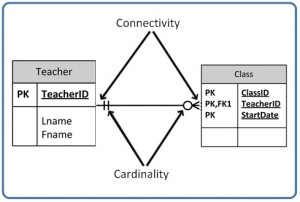
The outermost symbol of the relationship symbol, on the other hand, represents the connectivity between the two tables. Connectivity is the relationship between two tables, e.g., one to one or one to many. The only time it is zero is when the FK can be null. When it comes to participation, there are three options to the relationship between these entities: either 0 (zero), 1 (one) or many. In Figure 9.2, for example, the connectivity is 1 (one) on the outer, left-hand side of this line and many on the outer, right-hand side.
Figure 9.3. shows the symbol that represents a one to many relationship.

In Figure 9.4, both inner (representing cardinality) and outer (representing connectivity) markers are shown. The left side of this symbol is read as minimum 1 and maximum 1. On the right side, it is read as: minimum 1 and maximum many.

Relationship Types
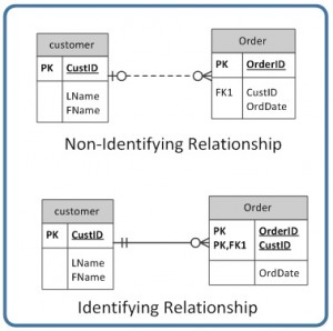
The line that connects two tables, in an ERD, indicates the relationship type between the tables: either identifying or non-identifying. An identifying relationship will have a solid line (where the PK contains the FK). A non-identifying relationship is indicated by a broken line and does not contain the FK in the PK. See the section in Chapter 8 that discusses weak and strong relationships for more explanation.
Optional relationships
In an optional relationship, the FK can be null or the parent table does not need to have a corresponding child table occurrence. The symbol, shown in Figure 9.6, illustrates one type with a zero and three prongs (indicating many) which is interpreted as zero OR many.

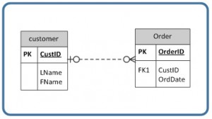
For example, if you look at the Order table on the right-hand side of Figure 9.7, you’ll notice that a customer doesn’t need to place an order to be a customer. In other words, the many side is optional.
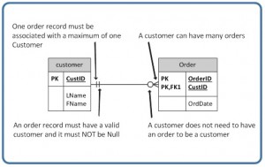
The relationship symbol in Figure 9.7 can also be read as follows:
- Left side: The order entity must contain a minimum of one related entity in the Customer table and a maximum of one related entity.
- Right side: A customer can place a minimum of zero orders or a maximum of many orders.
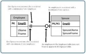
Figure 9.8 shows another type of optional relationship symbol with a zero and one, meaning zero OR one. The one side is optional.
Figure 9.9 gives an example of how a zero to one symbol might be used.
Mandatory relationships
In a mandatory relationship, one entity occurrence requires a corresponding entity occurrence. The symbol for this relationship shows one and only one as shown in Figure 9.10. The one side is mandatory.

See Figure 9.11 for an example of how the one and only one mandatory symbol is used.
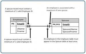
Figure 9.12 illustrates what a one to many relationship symbol looks like where the many side is mandatory.

Refer to Figure 9.13 for an example of how the one to many symbol may be used.

So far we have seen that the innermost side of a relationship symbol (on the left-side of the symbol in Figure 9.14) can have a 0 (zero) cardinality and a connectivity of many (shown on the right-side of the symbol in Figure 9.14), or one (not shown).
However, it cannot have a connectivity of 0 (zero), as displayed in Figure 9.15. The connectivity can only be 1.

The connectivity symbols show maximums. So if you think about it logically, if the connectivity symbol on the left side shows 0 (zero), then there would be no connection between the tables.
The way to read a relationship symbol, such as the one in Figure 9.16, is as follows.
- The CustID in the Order table must also be found in the Customer table a minimum of 0 and a maximum of 1 times.
- The 0 means that the CustID in the Order table may be null.
- The left-most 1 (right before the 0 representing connectivity) says that if there is a CustID in the Order table, it can only be in the Customer table once.
- When you see the 0 symbol for cardinality, you can assume two things: T
- the FK in the Order table allows nulls, and
- the FK is not part of the PK since PKs must not contain null values.
Key Terms
cardinality: expresses the minimum and maximum number of entity occurrences associated with one occurrence of a related entity
connectivity: the relationship between two tables, e.g., one to one or one to many
constraints: the rules that force DBMSs to check that data satisfies the semantics
entity integrity: requires that every table have a primary key; neither the primary key, nor any part of it, can contain null values
identifying relationship: where the primary key contains the foreign key; indicated in an ERD by a solid line
integrity constraints: logical statements that state what data values are or are not allowed and which format is suitable for an attribute
mandatory relationship:one entity occurrence requires a corresponding entity occurrence.
non-identifying relationship: does not contain the foreign key in the primary key; indicated in an ERD by a dotted line
optional relationship: the FK can be null or the parent table does not need to have a corresponding child table occurrence
orphan record: a record whose foreign key value is not found in the corresponding entity – the entity where the primary key is located
referential integrity: requires that a foreign key must have a matching primary key or it must be null
relational database management system (RDBMS): a popular database system based on the relational model introduced by E. F. Codd of IBM’s San Jose Research Laboratory
relationship type: the type of relationship between two tables in an ERD (either identifying or non-identifying); this relationship is indicated by a line drawn between the two tables.
Exercises
Read the following description and then answer questions 1-5 at the end.
The swim club database in Figure 9.17 has been designed to hold information about students who are enrolled in swim classes. The following information is stored: students, enrollment, swim classes, pools where classes are held, instructors for the classes, and various levels of swim classes. Use Figure 9.17 to answer questions 1 to 5.
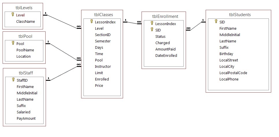
The primary keys are identified below. The following data types are defined in the SQL Server.
tblLevels
Level – Identity PK
ClassName – text 20 – nulls are not allowed
tblPool
Pool – Identity PK
PoolName – text 20 – nulls are not allowed
Location – text 30
tblStaff
StaffID – Identity PK
FirstName – text 20
MiddleInitial – text 3
LastName – text 30
Suffix – text 3
Salaried – Bit
PayAmount – money
tblClasses
LessonIndex – Identity PK
Level – Integer FK
SectionID – Integer
Semester – TinyInt
Days – text 20
Time – datetime (formatted for time)
Pool – Integer FK
Instructor – Integer FK
Limit – TinyInt
Enrolled – TinyInt
Price – money
tblEnrollment
LessonIndex – Integer FK
SID – Integer FK (LessonIndex and SID) Primary Key
Status – text 30
Charged – bit
AmountPaid – money
DateEnrolled – datetime
tblStudents
SID – Identity PK
FirstName – text 20
MiddleInitial – text 3
LastName – text 30
Suffix – text 3
Birthday – datetime
LocalStreet – text 30
LocalCity – text 20
LocalPostalCode – text 6
LocalPhone – text 10
Implement this schema in SQL Server or access (you will need to pick comparable data types). Submit a screenshot of your ERD in the database.
- Explain the relationship rules for each relationship (e.g., tblEnrollment and tblStudents: A student can enroll in many classes).
- Identify cardinality for each relationship, assuming the following rules:
- A pool may or may not ever have a class.
- The levels table must always be associated with at least one class.
- The staff table may not have ever taught a class.
- All students must be enrolled in at least one class.
- The class must have students enrolled in it.
- The class must have a valid pool.
- The class may not have an instructor assigned.
- The class must always be associated with an existing level.
- Which tables are weak and which tables are strong (covered in an earlier chapter)?
- Which of the tables are non-identifying and which are identifying?
Image Attributions
Figures 9.3, 9.4, 9.6, 9.8, 9.10, 9.12, 9.14 and 9.15 by A. Watt.
