Chapter 4. VPN
4.1 IPsec VPN
Learning Objectives
- Configure an IPsec VPN
- Configure a site-to-site VPN

Configuration
| Device | IP address | Access |
|---|---|---|
| WebTerm2 | 192.168.0.2/24 | – |
| VPC | DHCP Client | – |
| Ethernet Switch1-2 | – | – |
| FortiGate | Port 1: DHCP Client
Port 2: 192.168.0.1/24 DHCP Server (192.168.0.10 to 192.168.0.20) |
ICMP
HTTP HTTPS |
| Windows | DHCP Client | – |
Before you begin the configuration, please remember with VPC’s and Web terms this is how we edit their IP settings for static and or DHCP Addressing:
Before dragging in your web terms or other devices remember to always choose GNS3 VM:
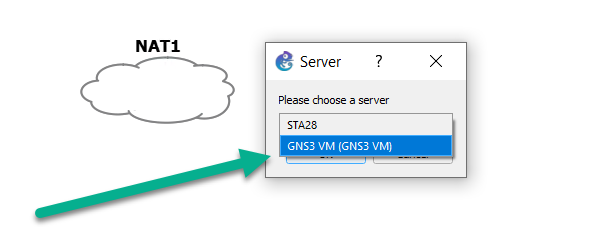
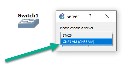
- Set a DHCP server on interface port2 (Range of IP address should be: 192.168.0.20 to 192.168.0.30, DNS: 4.2.2.4).

Figure 4.4: Set DHCP IP address 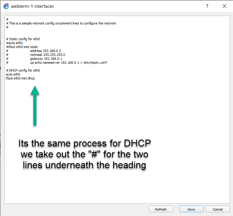
Figure 4.5: Enable DHCP client 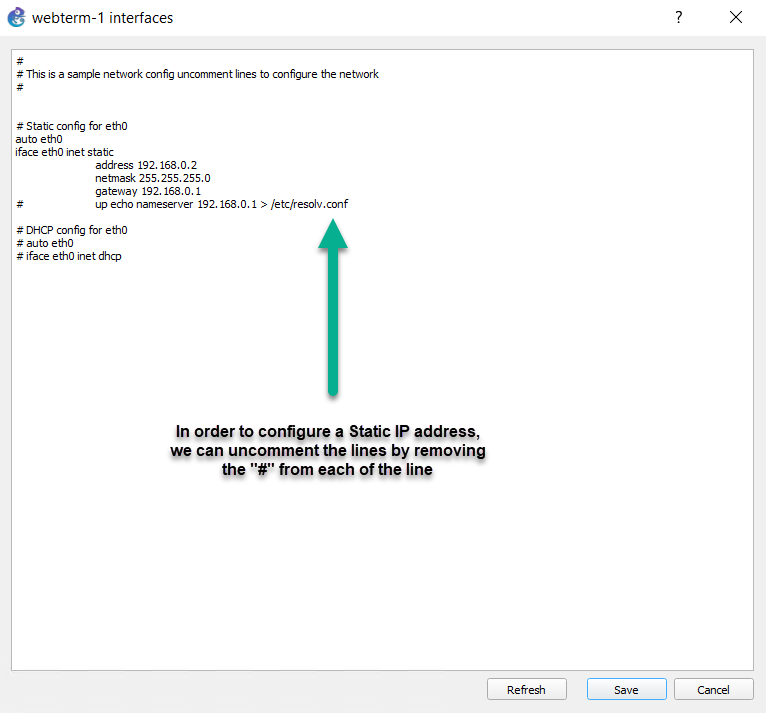
Figure 4.6: Configure a static IP address - Go to User & Authentication > User Group > Create New:
- Name: VPN_GRP_A0ID
- TYPE: Firewall
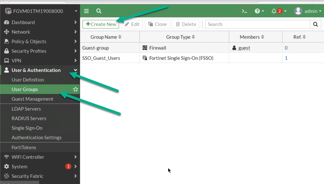
Figure 4.7: Create a user group 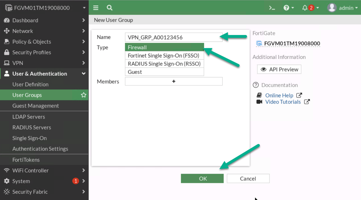
Figure 4.8: Create a group in the firewall - Go to User & Authentication > User Definition > Create a User:
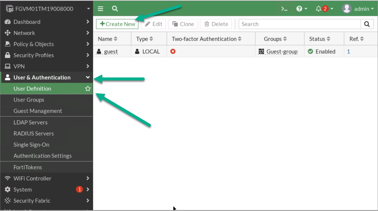
Figure 4.9: Create a new user 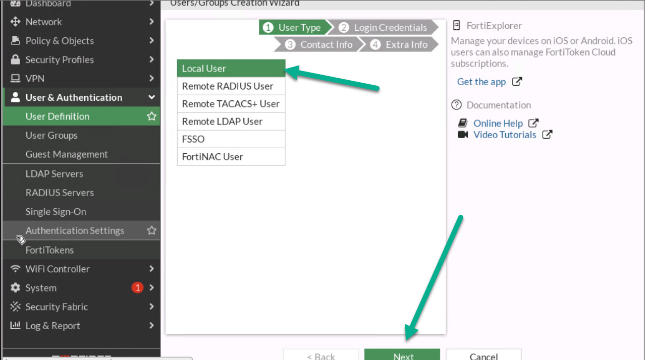
Figure 4.10: Create a local user 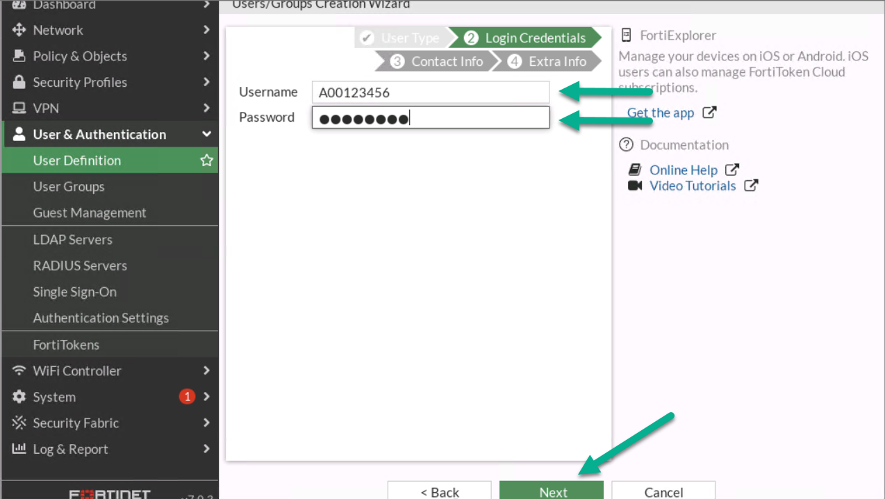
Figure 4.11: Configure login credentials for the user 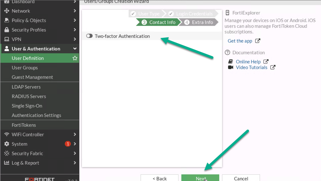
Figure 4.12: Contact info - Assign User Group to your profile.
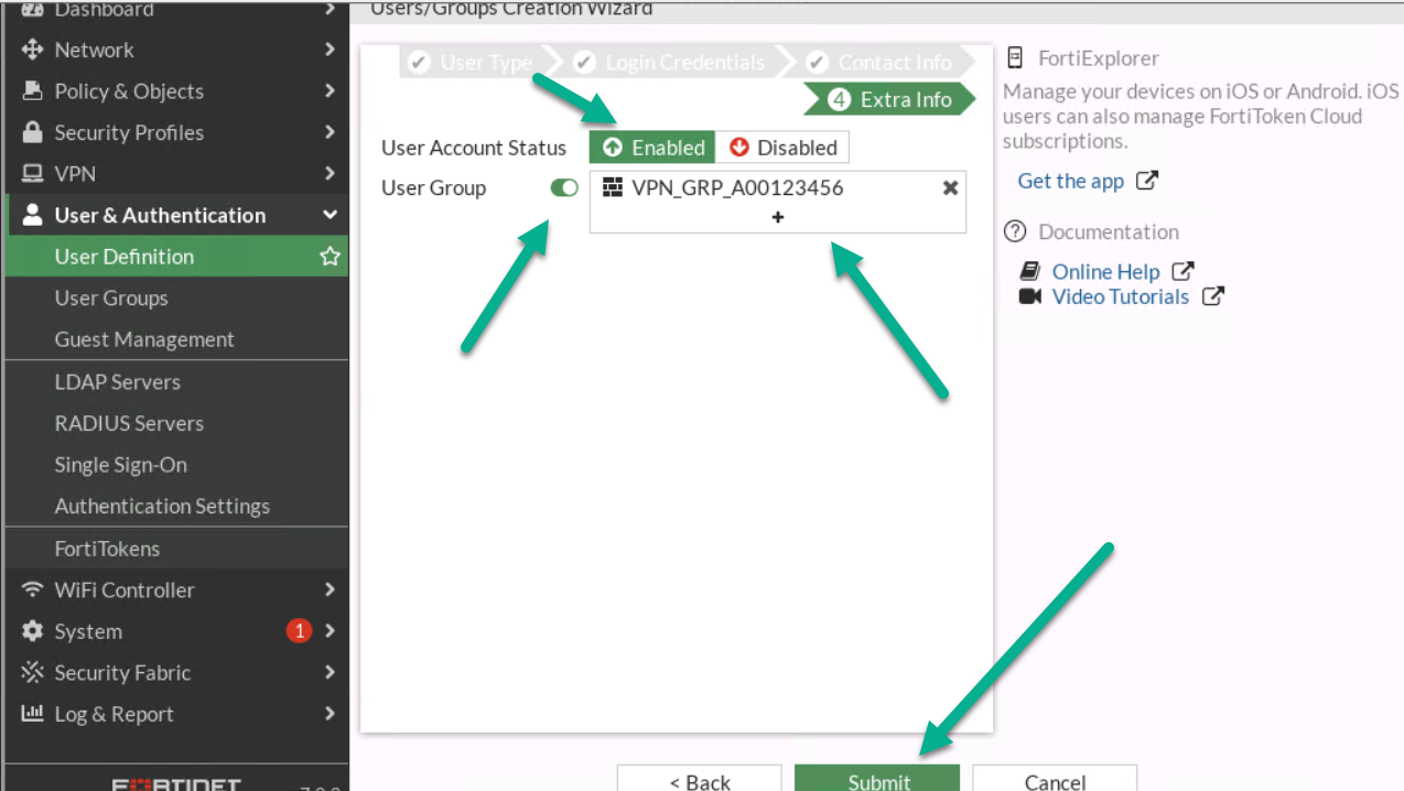
Figure 4.13: Assign a user to the group 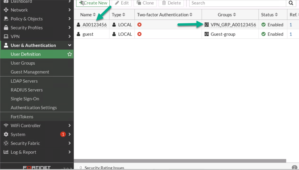
Figure 4.14: Verify configuration - Go to VPN > IPsec Wizard.
- First:
- Select Name: A0ID- VPN(A0ID is a student ID)
- Template Type: Remote Access
- Remote Type Device: FortiClient
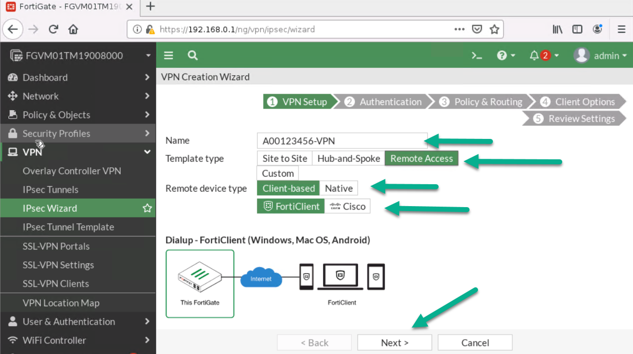
Figure 4.15: Create a VPN connection - Then:
- Incoming Interface: Port1
- Pre-shared Key: <Select a key like a password>
- User Group: VPN_GRP_A0ID
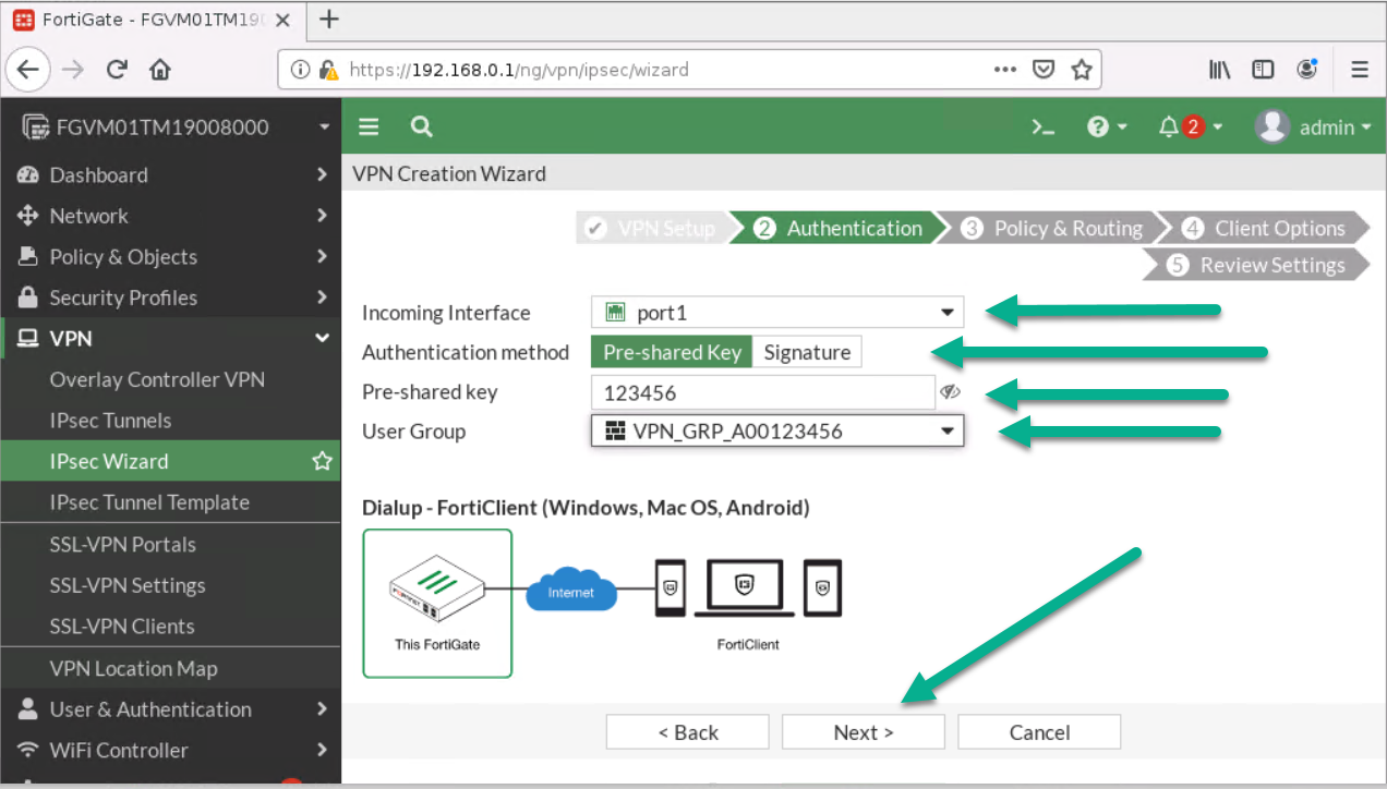
Figure 4.16: Configure authentication - Next:
- Local Interface: Port 2
- Local Address: Add your local range of IP address (192.168.0.0/24)
- Client Range: 172.16.0.1 to 172.16.0.10
- Subnet Mask: 255.255.255.0
- Disable Split Tunneling
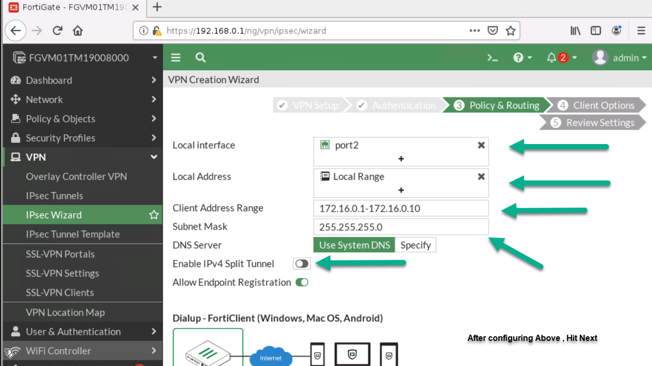
Figure 4.17: Configure Policy & Routing 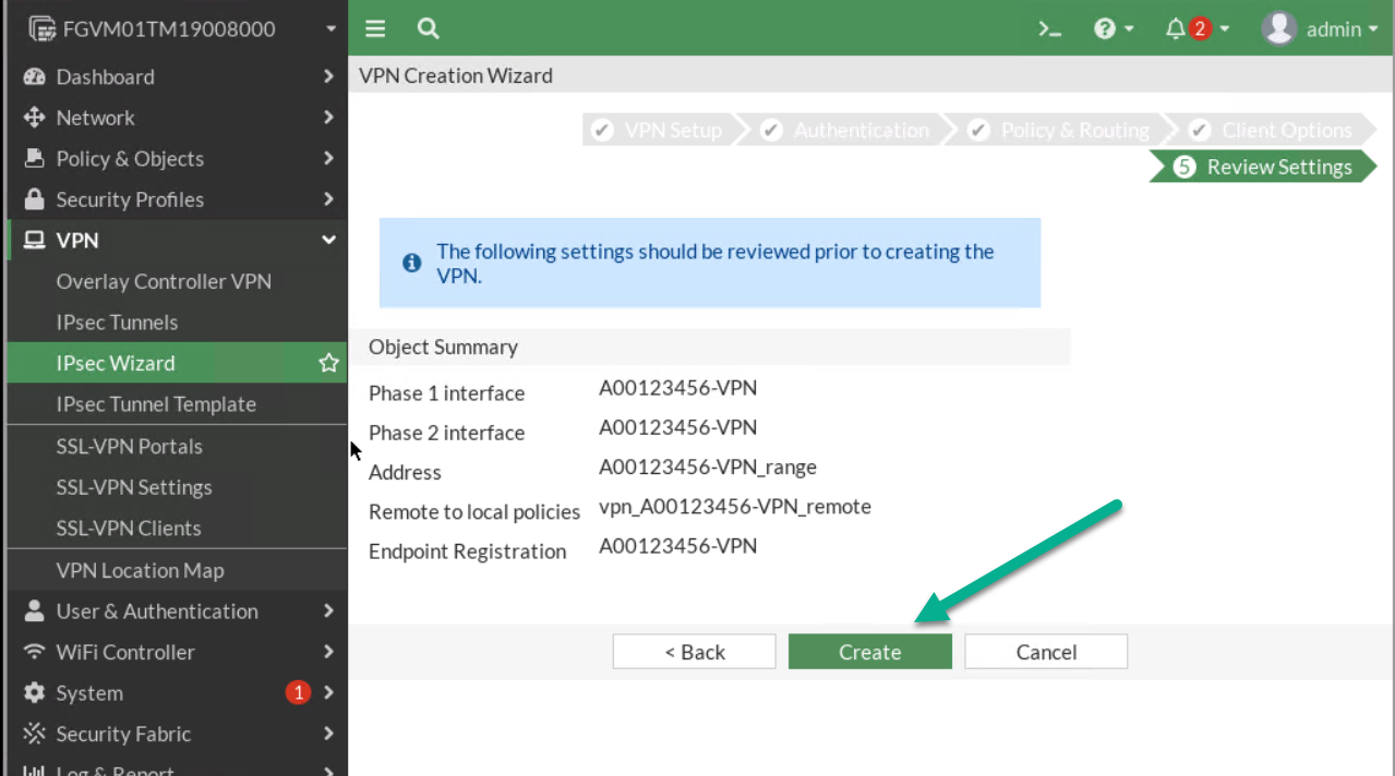
Figure 4.18: Review Settings
- First:
- On Windows machine, download FortiClient from Fortinet. Install the FortiClient and configure IPsec as set in the previous steps. Your remote Gateway IP should be the Port1 IP address.
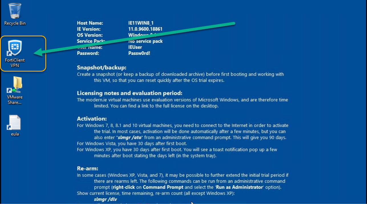
Figure 4.19: Install FortiClient on Windows -
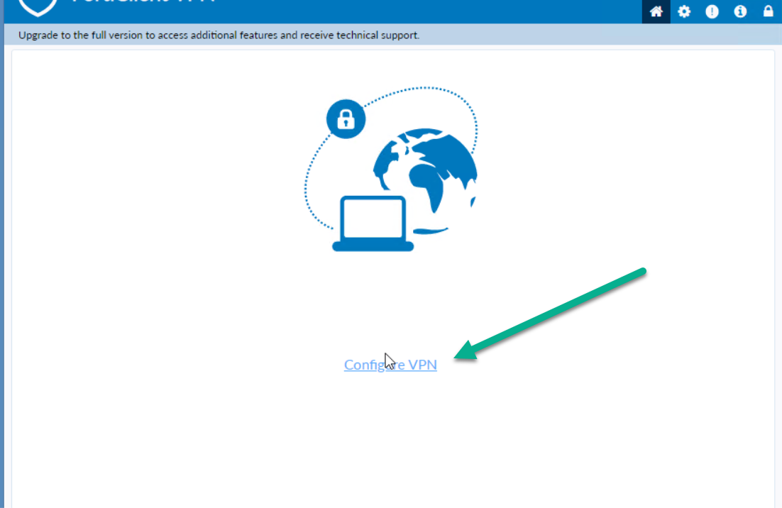
Figure 4.20: Configure VPN in FortiClient -
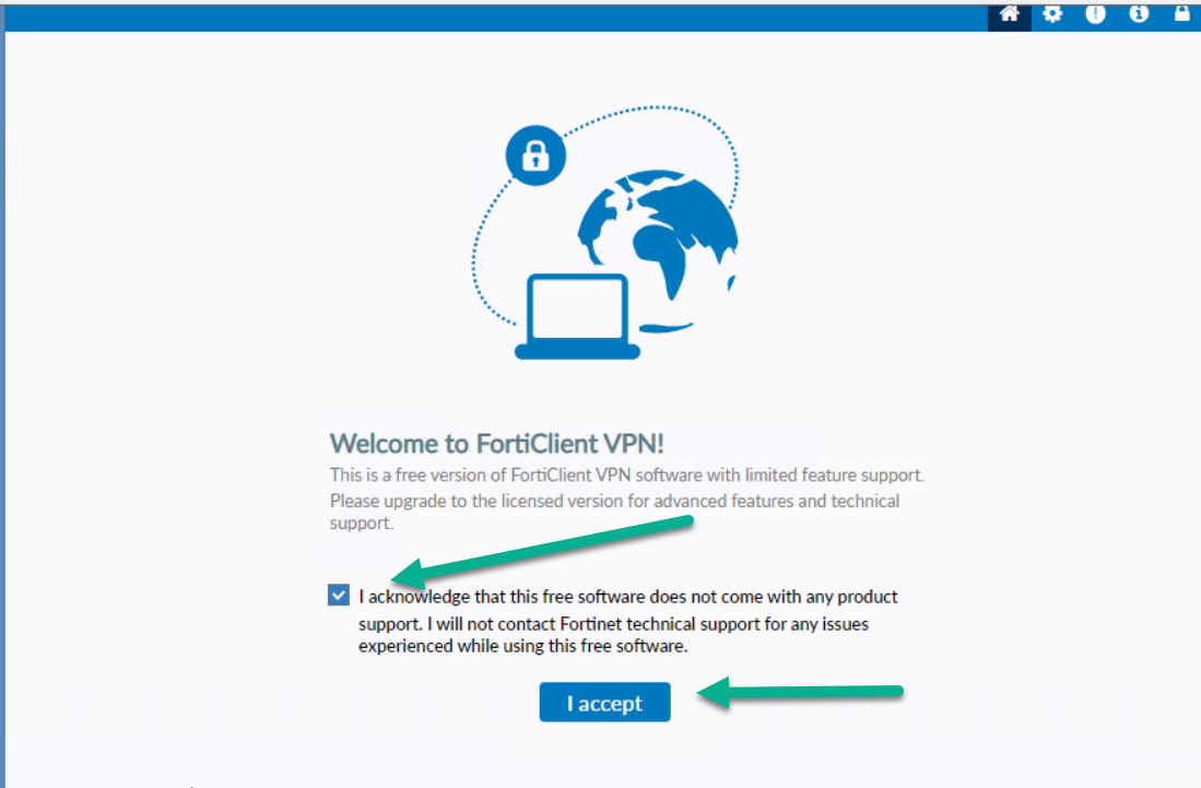
Figure 4.21: Accept FortiClient Free Licence -
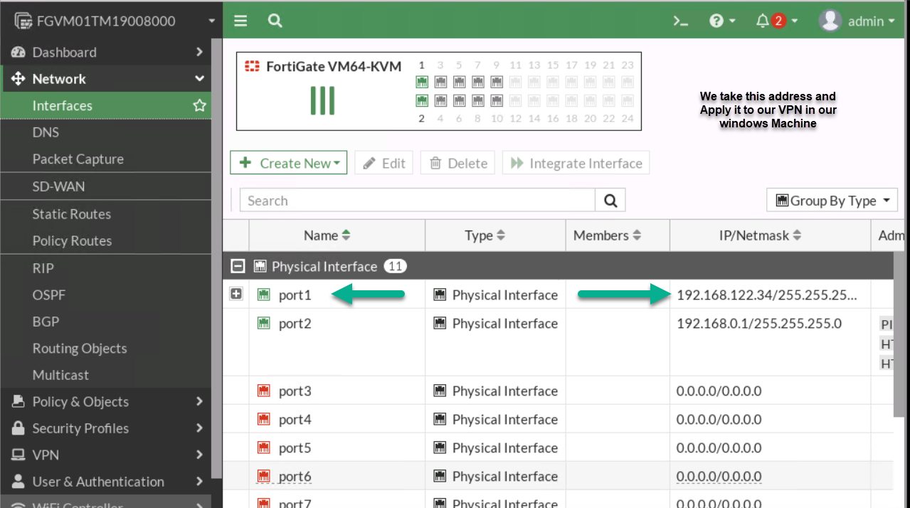
Figure 4.22: Port1 IP Address -
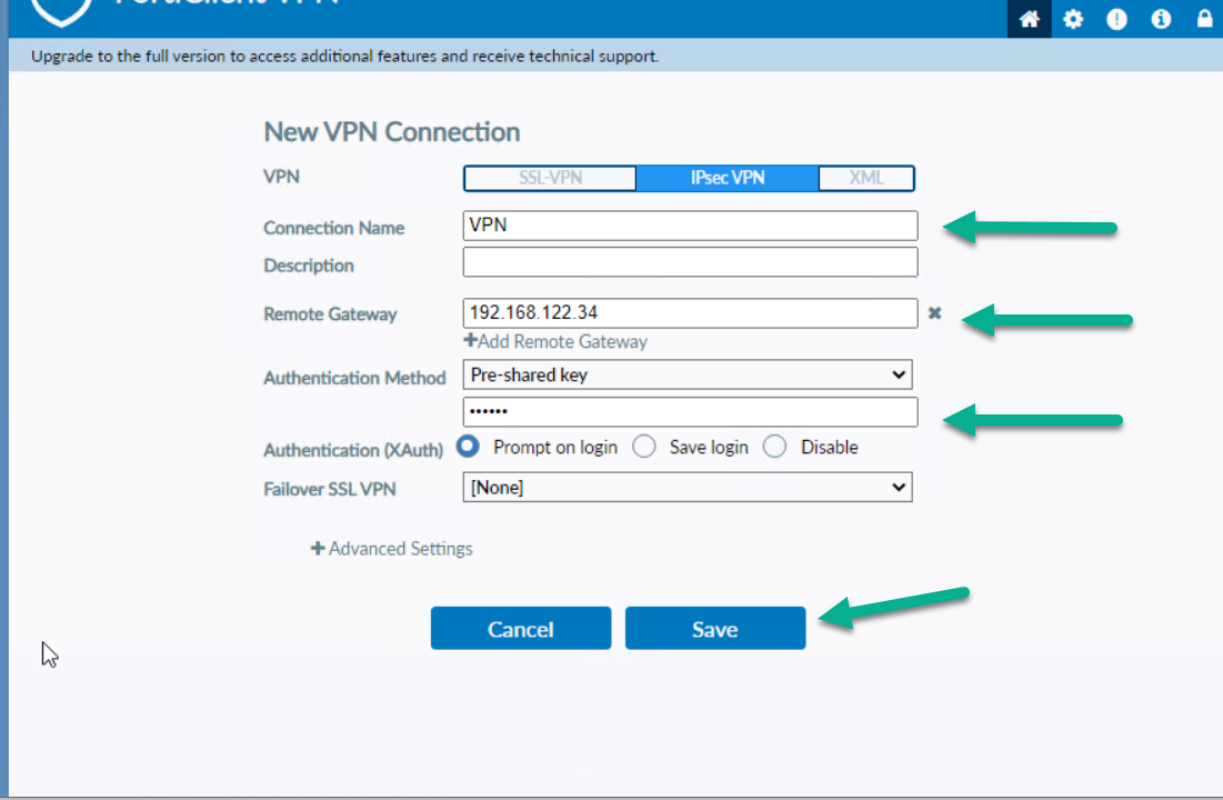
Figure 4.23: Configure FortiClient Remote Gateway and Pre-shared key - You should be able to ping from Windows to VPC.
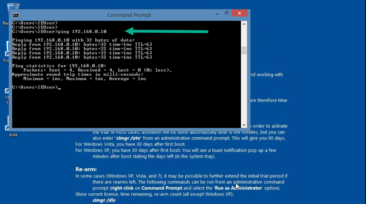
Figure 4.24: Verify configuration
Site-to-Site VPN (IPsec VPN)

To validate Firewalls licences, we are going to connect them to the Internet.

| Device | IP address | Access |
|---|---|---|
| Fortigate1 | 10.10.10.1/24 | ICMP-HTTP-HTTPS |
| Fortigate2 | 10.10.10.2/24 | ICMP-HTTP-HTTPS |
| WebTerm1 | 192.168.20.2/24 | – |
| WebTerm2 | 192.168.10.2/24 | – |
- On the FG1, go to VPN > IPsec Wizard and select Site to Site – FortiGate.

Figure 4.27: VPN Setup - Select Site2Site/ FortiGate /No Nat. Enter Remote IP: 10.10.10.2/24, outgoing interface: port3.

Figure 4.28: Authentication - Local Interface: port2, IP: 192.168.20.0/24, Remote subnet: 192.168.10.0/24. Through the wizard, FortiGate creates two policies and two static routes in the firewall.

Figure 4.29: Policy & Routing - On the FG2, go to VPN > IPsec Wizard and select Site-to-Site – FortiGate.

Figure 4.30: Set up FG2 - Do the same configuration for FG2 (remote IP is 10.10.10.1/24 and local IP is 192.168.10.0/24).

Figure 4.31: Authentication in FG2 -

Figure 4.32: Policy & Routing in FG2 -

Figure 4.33: Configure IPsec Tunnels Then, go to your IPsec Tunnels and double click on Inactive.
On the next windows, right click on the tunnel > Bring UP > All Phase 2 selectors. Then, your tunnel should be up!

Figure 4.34: Bring up IPsec Tunnel 
Figure 4.35: Verify the status of the tunnel - Go to Logs & Reports > Event > VPN Event and verify your configuration.

Figure 4.36: Verify configuration You should be able to ping from WebTerm1 to WebTerm2.

Figure 4.37: Verify configuration

