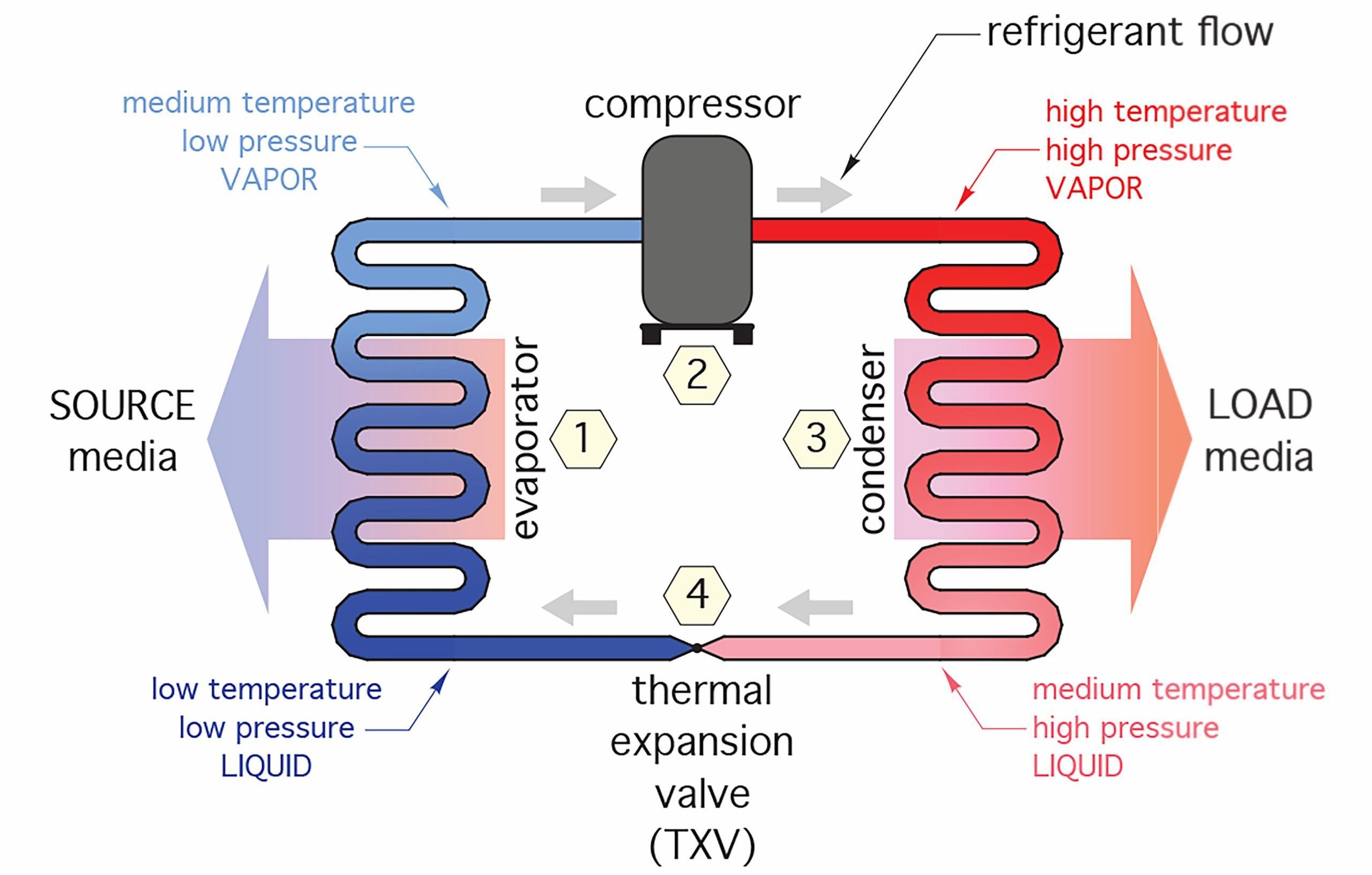
Heat pumps heat or cool by moving energy, and have expressions of efficiency that go along with each process. On the heating side, it will have a heating capacity expressed in btuh and an efficiency expressed by the term “Coefficient of Performance” or “COP”. On the cooling side, it will have a cooling capacity usually expressed in “tons of cooling” and an efficiency expressed by the term “Energy Efficiency Rating” or “EER”.
Heating Performance of Heat Pumps
The expression of the heating capacity of a gas-fired furnace is centred around the quantity and type of fuel being burned (eg. 75,000 btuh natural gas or propane) and the construction of the furnace (mid-or-high efficiency) and is therefore fairly straightforward. In other words, the conditions that determine its heat output are fairly finite and will not vary depending on conditions such as the temperature of the return. However, the conditions that determine the heating capacity of a water-to-water heat pump can vary greatly. Temperature of the source media, temperature of the load media, as well as the flow rates of both the source and load media can change, and they all have an effect on the heat pump’s heating capacity. Formulas and graphs must be consulted that take into account the variations in these conditions. An example of a chart showing the heating capacity in btuh of a water-to-water heat pump is shown in Figure 1 below.
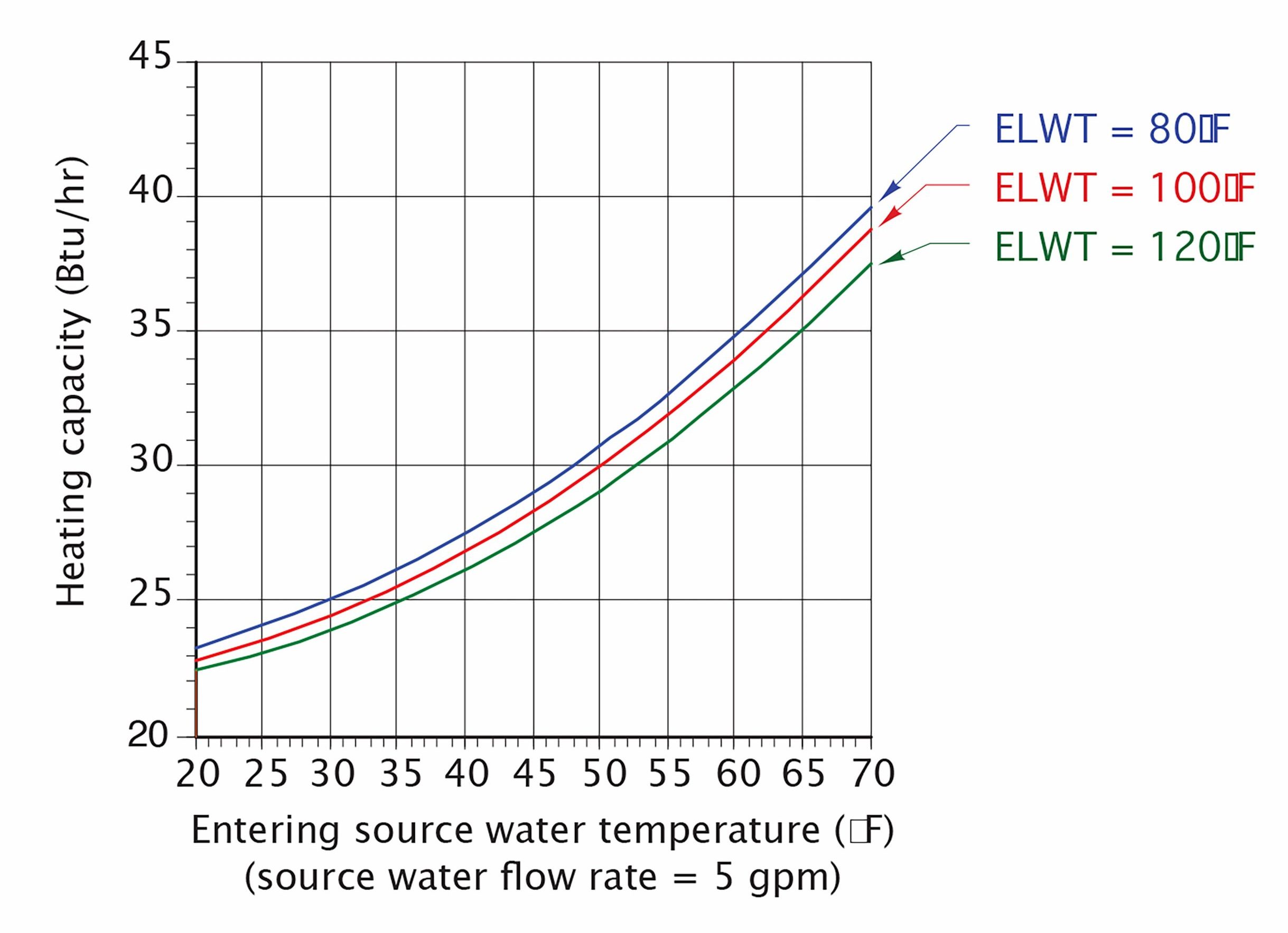
Figure 1 Heating capacity for a water-to-water heat pump
The vertical left side of the graph represents the heating capacity in thousands of btus per hour or btuh. The bottom of the graph represents the temperature of the water that could be in contact with the evaporator (entering source water temperature) and the three curved lines indicate the possible temperatures of water entering the condenser (entering load temperatures). To demonstrate the use of this graph, let’s say that it’s the month of September, and the summer sun has contributed to a ground temperature in contact with the earth loop (evaporator) of 60°F (16°C). If the temperature of the water entering the condenser from the load is 80°F (27°C), the heating capacity of the heat pump would be approximately 35,000 btuh as seen in Figure 2a below.
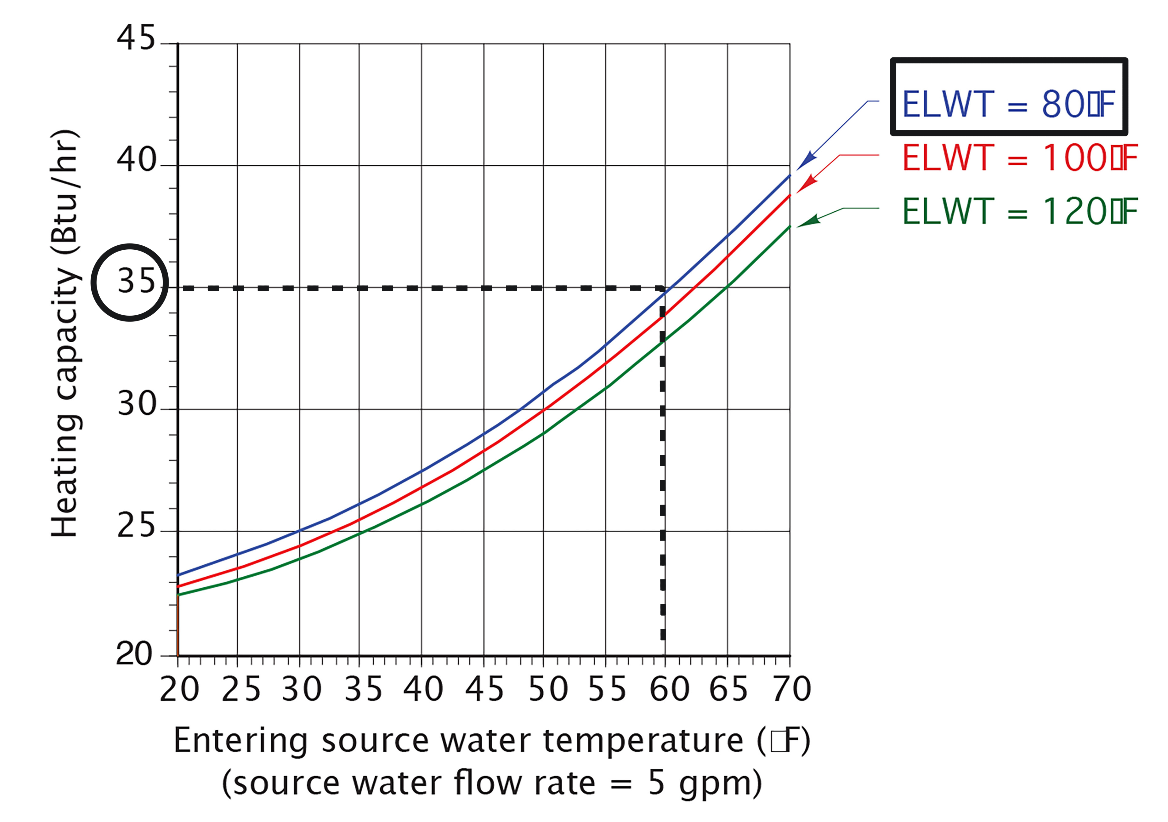
Figure 2a Heat capacity at 60°F (16°C) ground temperature
However, with the same water temperature entering the condenser on the load side, the heat pump’s heating capacity in March, when the ground temperature may be as low as 35°F (2°C), drops to approximately 26,000 btus/hr as seen in Figure 2b.
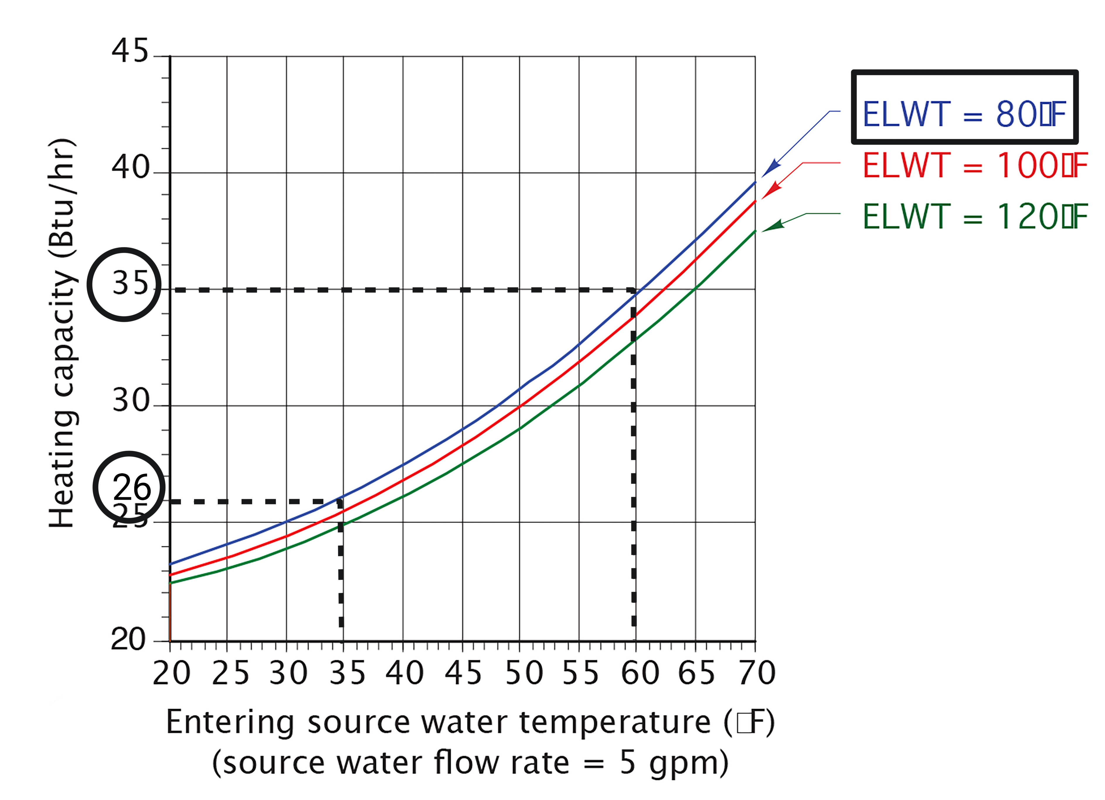
Figure 2b Heat capacity at 35° (2°C) ground temperature
This significant difference of over 25% in heat output, depending on time of year, would have to be allowed for when designing the heat emitters and distribution system.
The above examples show the change in heating capacity resulting from a change in entering source water temperature. When looking at the curved lines in those examples that represent the entering load water temperature, it should be plain to see that the lower the entering temperature at the condenser, the higher the btuh output. This illustrates that these water-to-water heat pumps work best when the output or load temperature is lower, such as with a radiant floor system, and when the source entering temperature is higher.
Equations are used to calculate the temperatures of the water leaving the load side (condenser) of the heat pump, depending on the water flow rate (USGPM) and current heating capacity. These factors, in turn, would be used to calculate the other factors involved in heating capacity determination. These equations are fairly involved and are, at this point, unnecessary to wade through, so for simplicity, rather than using examples of these formulas, a summary of the effects of the variables that are involved in the heating side of a water-to-water heat pump are as follows;
- The higher the entering source water temperature (bottom of graph), the greater the heating capacity
- The lower the entering load water temperature (curved diagonal lines), the greater the heating capacity
- The higher the flow rate through the evaporator and condenser (solid vs dotted curved lines), the greater the heating capacity
The graph shown below as Figure 3 illustrates these statements of summary.
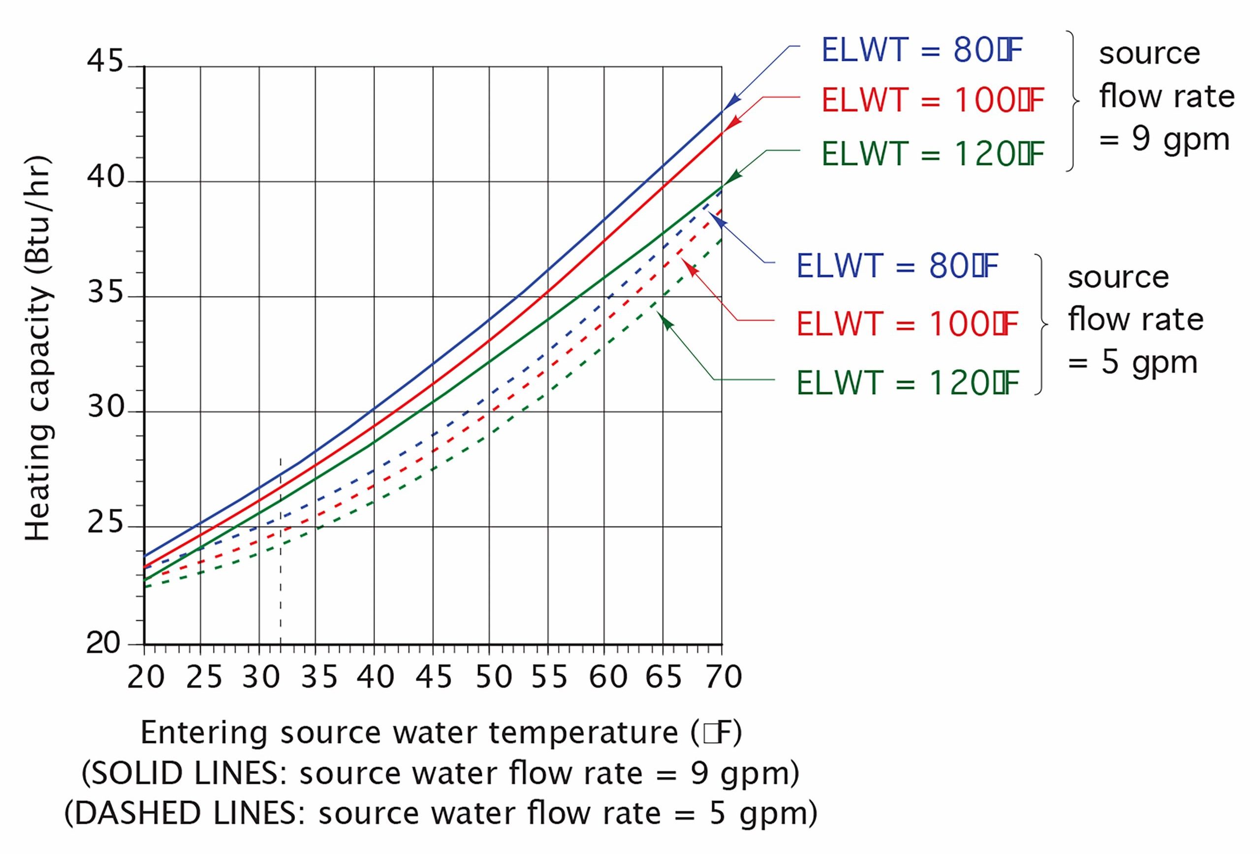
Figure 3 Heating capacity graph
Heating and cooling capacities of refrigeration-based equipment are traditionally referred to in the trade by how many “tons” of cooling they can deliver. Before refrigeration systems were commonly available, blocks of ice were used for cooling buildings and processes. Once smaller, electrically-driven refrigeration systems came into being, they were rated by being compared to the equivalent amount of ice that could be melted in a day. A “ton” of cooling was then determined to be equivalent to 12,000 btuh and that expression is still commonly used today. So, for example, a water-to-water 3-ton heat pump would be capable of providing approximately 3 ×12,000 = 36,000 btuh of heating, depending upon the conditions described earlier.
Coefficient of Performance (COP)
Because the conditions affecting a heat pump’s heating capacity can vary, a method of determining the overall efficiency of a heat pump was necessary. This is known as the coefficient of performance, or “COP”. The term efficiency describes the desired output of a heating or cooling unit as compared to its necessary input and is normally expressed as a percentage. So, if a heating unit such as a furnace has an input (heat created by the burning of gas) of 100,000 btuh and an output (actual heat transferred to the airstream) of 94,000 btuh, it would have an efficiency of:
(94,000 ÷ 100,000) × 100 = 94%
For this equation to work, the expressions of energy used in the numerator and denominator must be the same.
Where heat pumps are concerned, the desired output is the rate that heat is to be transferred to the load and is expressed in btuh. The necessary input is the amount of electrical energy that must be used to operate the heat pump and is normally expressed in watts or volt-amps (VA). 1 watt = a volt x 1 amp, which is also equivalent to 3.413 btus. The expression for COP is then:
}}{\text{electric input (watts)}\times 3.413}")
The heat input in the denominator is only concerned with the electricity needed to operate the compressor, as the low-temperature heat being absorbed from the heat source medium is considered to be “free heat”. Thus, the definition of COP reflects only the “paid for” electrical input power as being the required input. The higher the COP, the higher the heat output rate to a load for a given rate of electrical energy input.
An example calculation of a COP is as follows:
Let’s assume that a heat pump is to deliver 37,000 btuh of heat to a load, and its electrical requirements to operate the heat pump are 12.5 amps at 240 volts, which is 3,000 watts. Using the formula above, we can calculate the COP as:
}}{\text{electric input (watts)}\times 3.413}\\ \text{COP}=\dfrac{37,000\text{ btuh}}{10,239\text{ btuh}}\\ \text{COP}=3.61\end{array}")
Note that the COP has the same units of measurement in the numerator as in the denominator, and so they cancel out to become simply a number, which is a ratio. The ratio represents how many units of heat output will be produced for every unit of electrical input energy used. The higher the COP, the more efficient it is. In the earlier comparisons to a 94% efficient gas furnace, for every 100,000 btus of heat created by burning of gas, only 94,000 btus are actually being transferred to the air being circulated. Comparatively, using a heat pump with a COP of 3.61, for every 100,000 btus of equivalent input heat, it would have an output of 361% of that, or 361,000 btus. It can be said, then, that heat pumps are capable of efficiencies of over 100%, and this makes them far more attractive for heating than does the burning of fossil fuels, which can approach but never exceed 100% due to the processes involved. The COP of a heat pump is very dependant upon the operating conditions. The closer the temperature that the source media is to the temperature of the load media, the higher the heat pump’s COP. This temperature difference between the two points is known as “temperature lift”, and so the smaller the lift, the higher the COP.
Cooling Performance of Heat Pumps
Just as on the heating side of a heat pump’s operation, there are two indicators that used to represent a heat pump’s cooling output, which are cooling capacity and EER, which stands for Energy Efficiency Ratio.
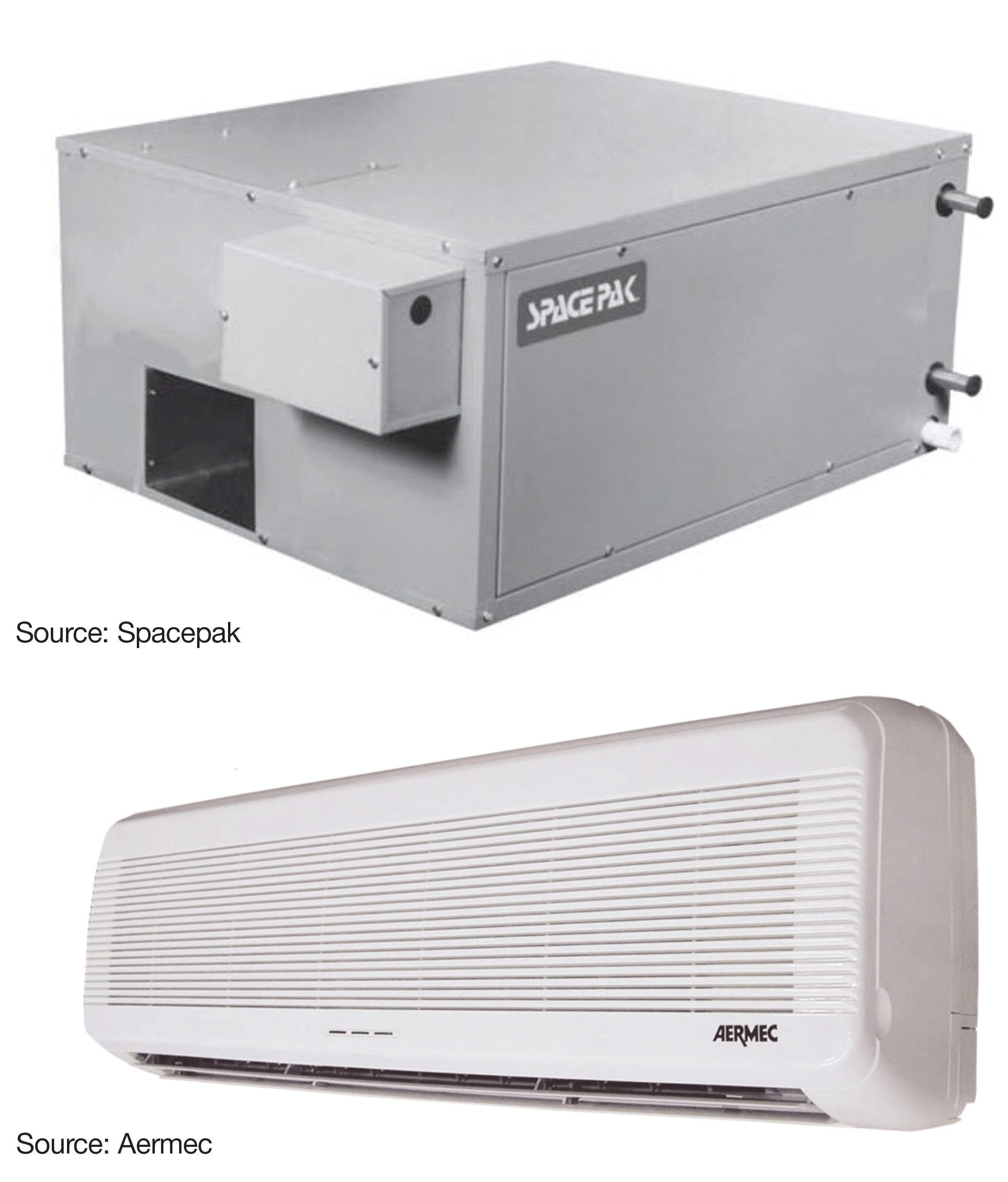
Total cooling capacity for a water-to-water heat pump combines sensible cooling and latent cooling, whereas water-to-air heat pumps have separate ratings for latent cooling and sensible cooling. This rating is affected by the temperatures of the fluid streams entering the evaporator and condenser and, to a lesser degree, by the flow rates of these two fluid streams. Figure 4 below represents the cooling capacity of a water-to-water heat pump with a nominal cooling capacity of 3 tons.
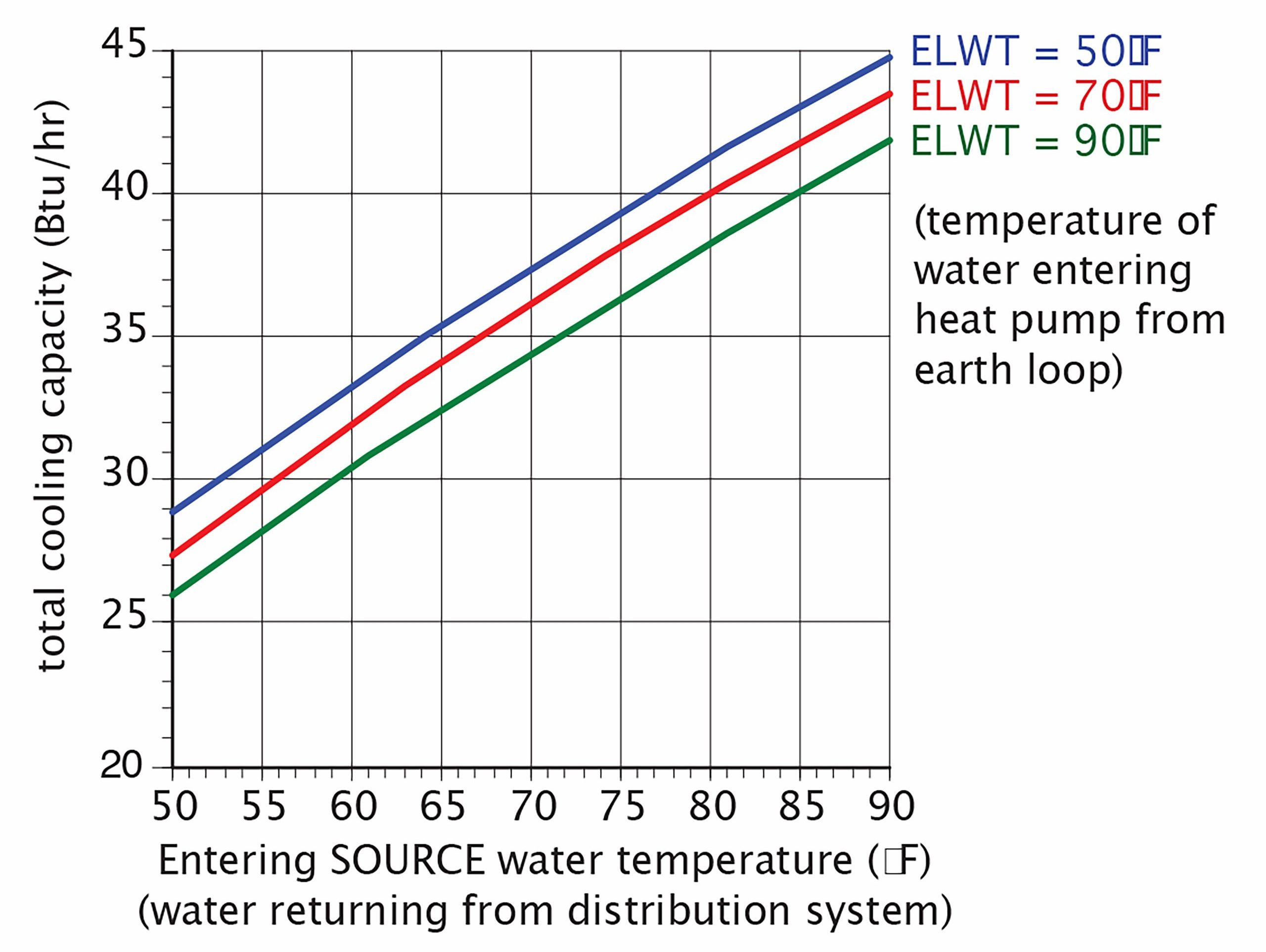
Figure 4 Typical 3-ton water-to-water heat pump cooling capacity
The horizontal axis shows the entering source water temperature, which when in cooling mode, would now be the return water from the distribution system. The curved diagonal lines represent the entering water temperature from the condenser, which now could be an earth loop, and the vertical axis is the total cooling capacity in thousands of btus per hour (btuh). As you can see, the lower the condenser (earth loop) water temperature, the higher the cooling capacity. As the temperature of the entering source water goes up, so does the heat pump’s cooling capacity. Thus, if the heat pump’s return water temperature from the distribution piping is 60°F (15°C) it has a greater cooling capacity than if the return water temperature was 50°F (10°C). It should also be able to be seen that, as the temperature of the fluid into which the heat is to be dissipated (e.g. earth loop) increases, the heat pump’s cooling capacity decreases.
Energy Efficiency Ratio (EER)
The common way of expressing the cooling efficiency of a heat pump is by a term called energy efficiency ratio, or simply “EER”. It is calculated in almost identical fashion to the COP with the exception that the numerator is now the cooling capacity rather than the heating capacity and is doesn’t get converted into btuh as it does in the calculation of COP. The equation for EER is:
}}{\text{electric input (watts)}}")
In effect, the EER for a water-to-water heat pump is an expression of how many btuh it can deliver for every Watt of electricity it takes to do so. The higher the EER of a heat pump, the less energy it requires to produce a certain amount of cooling. Just as in the determination of a COP, the EER is a function of the entering source water temperature and the entering load water temperature. Figure 5 below is a graph that represents the EER (vertical axis) of a water-to-water heat pump depending on the temperatures of the entering source water (eg. distribution system) at three different water temperatures entering the heat pump from the load (eg. earth loop).
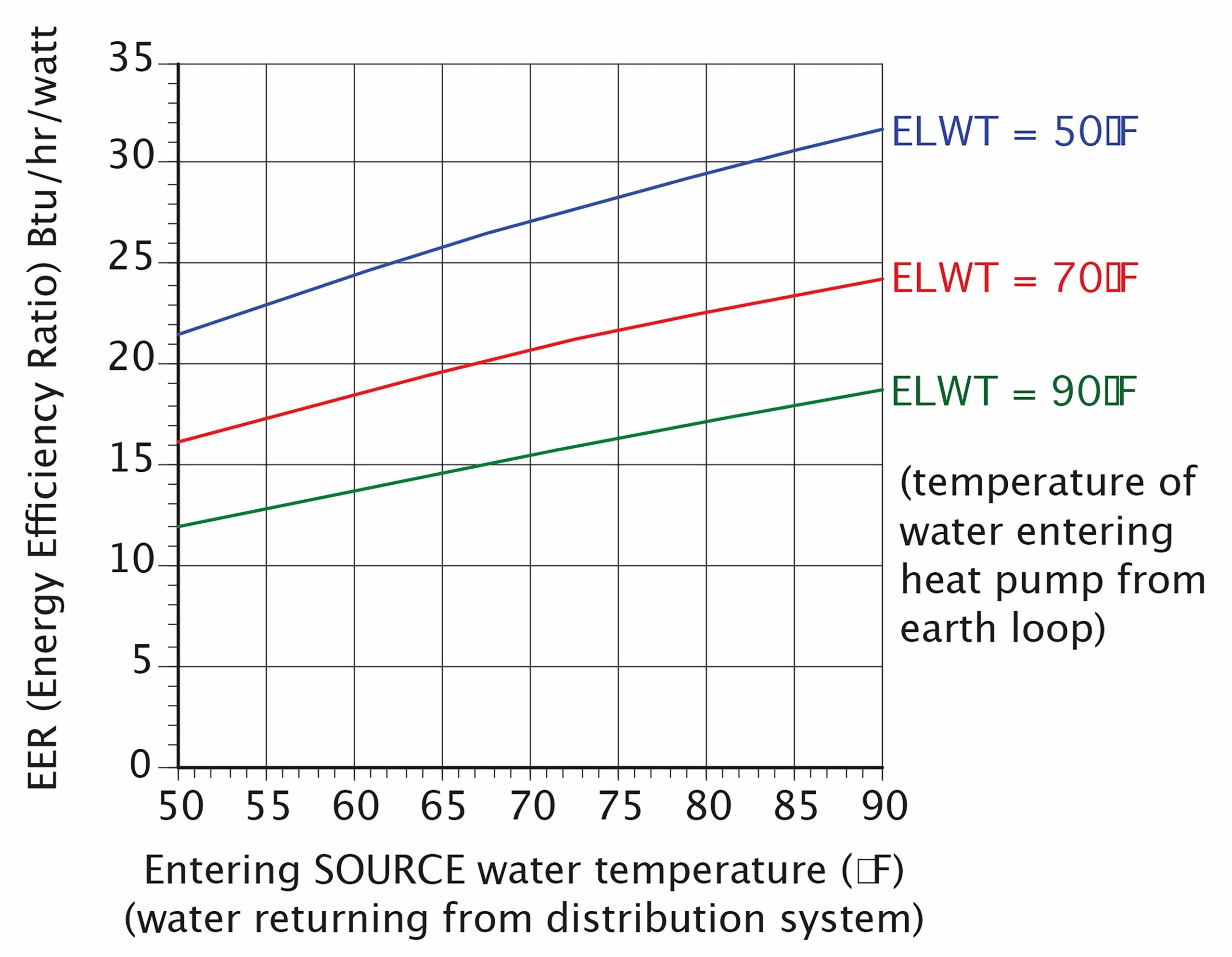
Figure 5 Energy efficiency ratios (EERs) of a typical water-to-water heat pump
The graph above shows that, as the temperature of the entering source water increases, so does the EER, and also that, as the temperature of the water entering the heat pump from the earth loop decreases, the EER increases. Just like in a water-to-water heat pump in heating mode, the less the temperature differential between the source and load water , the greater the cooling capacity and EER.
Also as in a water-to-water heat pump in heating mode, as the flow rate of water through either the evaporator or condenser, or both increases, so does its cooling capacity and EER. However, this increase is offset by the extra electrical energy in wattage to power the circulators causing the higher flow rates, and so, typically, flow rates are meant to be kept to no more than 3 GPM per ton of cooling.
Geothermal Heat Pumps
A heat pump gathers heat from a source and rejects it to a load. Ideally, the source should be as warm as possible in order to heat a building during the heating season, and conversely the “heat sink” should be as cool as possible for the same building in times of warm weather.
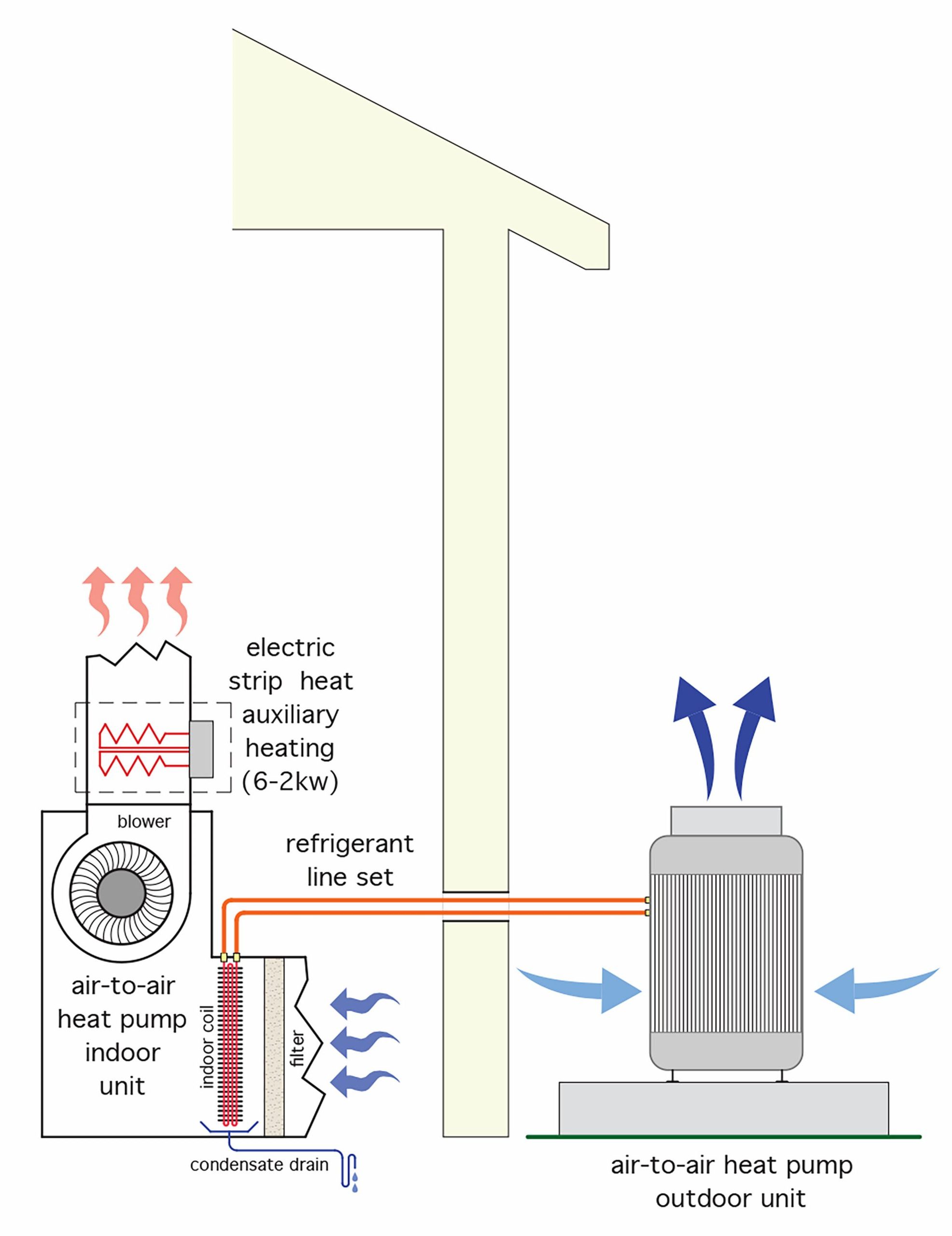
In many areas of Canada, the outdoor air temperatures can vary greatly between winter and summer. For instance, according to Appendix “C” of the BC Building Code, the Kelowna BC January 2.5% outdoor design temperature is 1°F (−17°C) and the July dry bulb temperature is 91°F (33°C). Such large variations in outdoor air temperature strain the ability of air-source heat pumps. Long stretches of cold weather cause heat pumps to operate at low COPs and correspondingly low heating capacities, with a need for high-cost electric resistance heating to augment the heat pumps’ output. Likewise, prolonged periods of extreme summer temperatures reduce the cooling capacity and EER of air source heat pumps. These facts make air source heat pumps less desirable than their ground source counterparts
Most people recognize that the temperature of the soil in different geographical areas of North America doesn’t fluctuate as much as does the temperature of air through the year. Soil within a few feet of the surface acts as a storage media for solar heat. The sun adds heat to the soil from spring through summer and this heat gradually dissipates through fall and winter. This slow process results in less temperature variation throughout the year and makes ground loops a better source media than air. Figure 6 below is a graph that illustrates the lessening of these variations as soil depth increases.
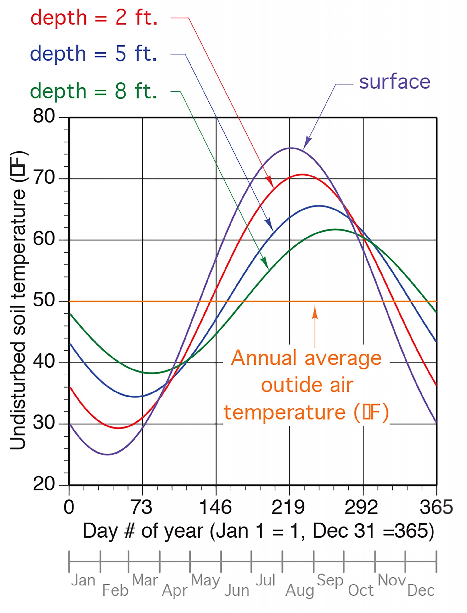
Figure 6 Soil temperatures at different depths and times of year
The curves in Figure 6 are based on a typical year in Albany, New York where the yearly average air temperature is 50°F (10°C). Moisture content and thermal conductivity of the soil also play a part in the soil’s ability to absorb and dissipate heat but in simplest terms, the deeper the soil depth, the less fluctuation in temperature through the year.
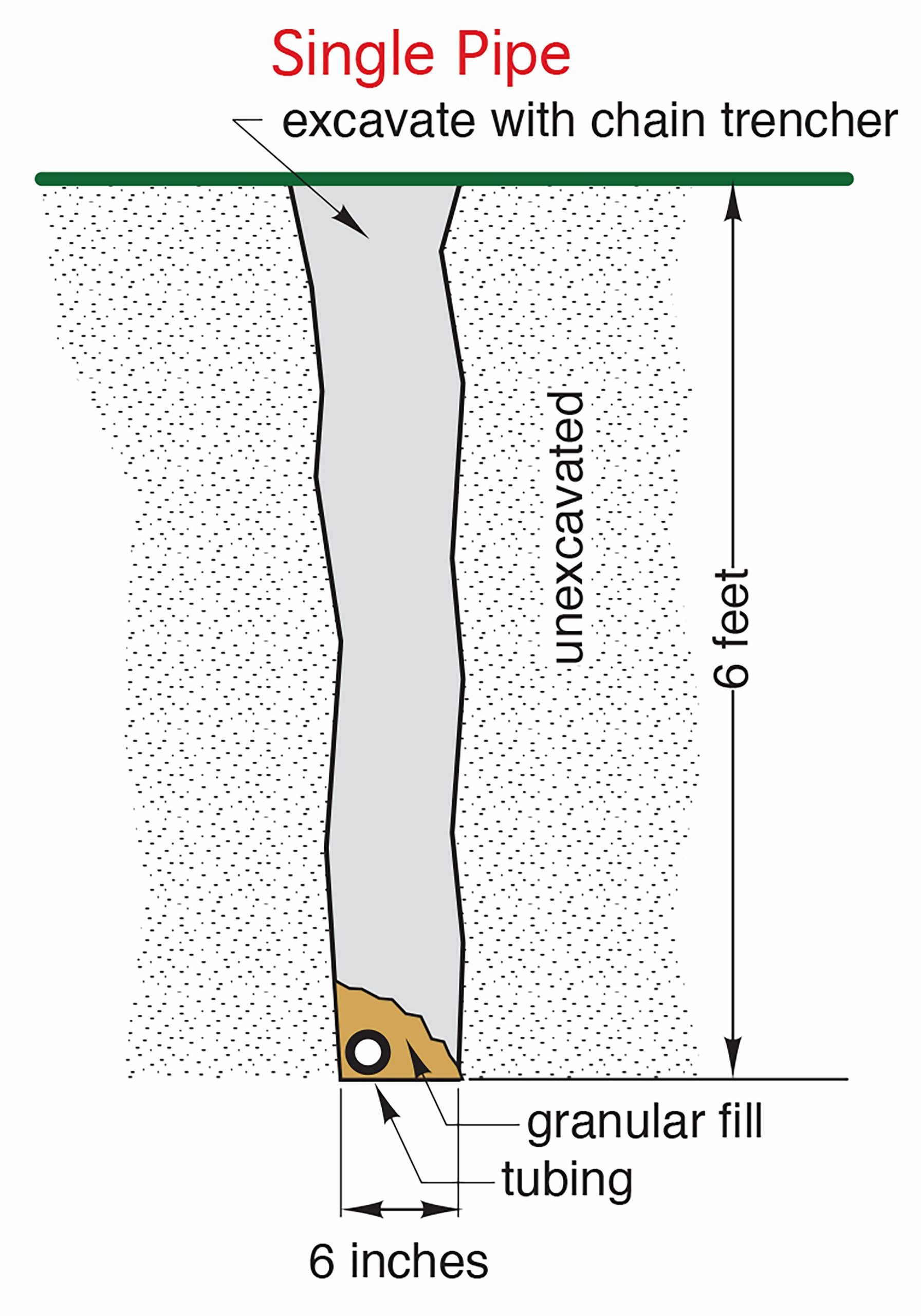
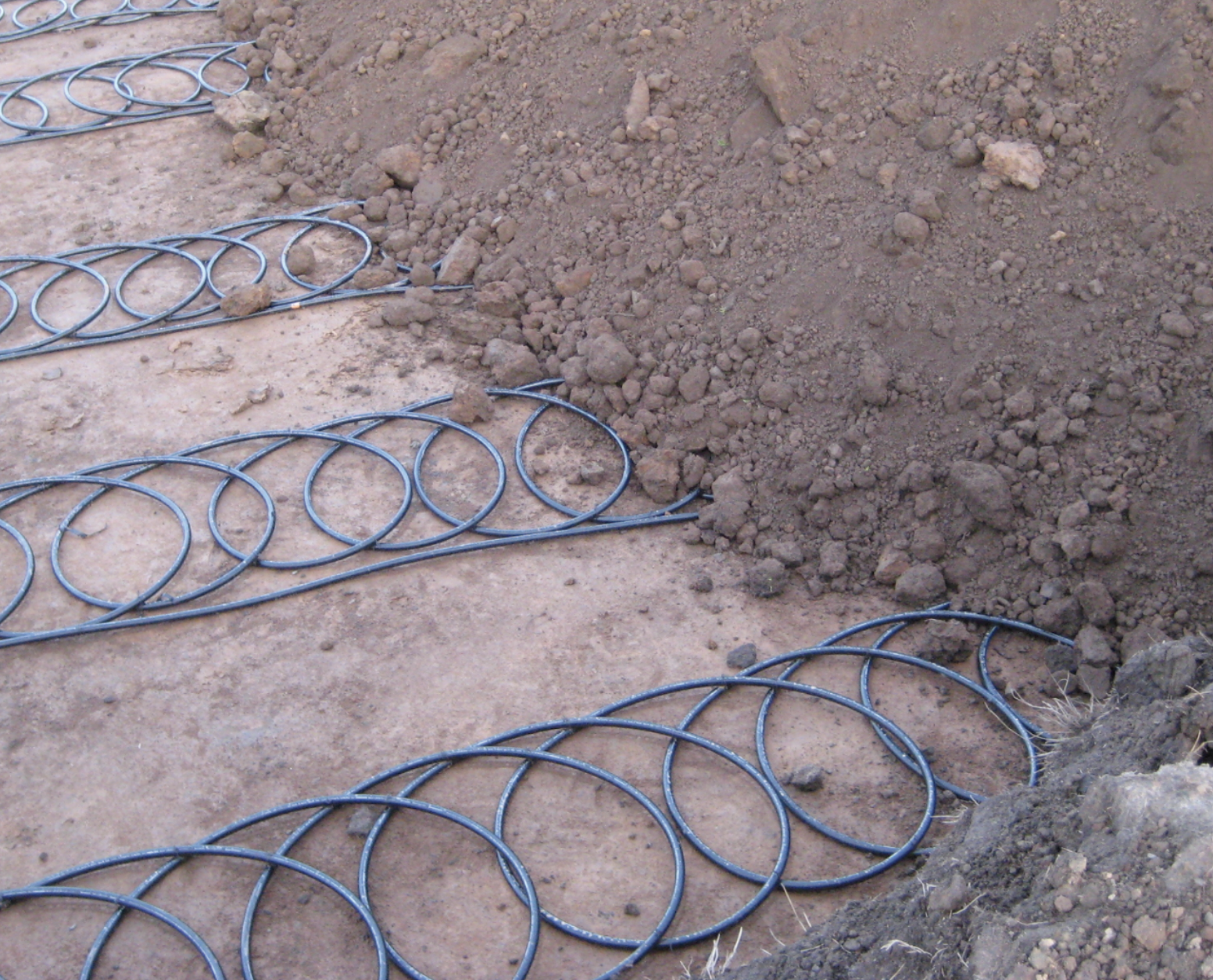
The first ground source refrigeration systems in North America appeared in the 1940s and ‘50s. The biggest initial challenge in using the soil as the media for an earth-loop piping system was coming up with piping that wasn’t too costly, was fairly easy to install and that would last many decades. Piping materials were the major stumbling block, in that copper, which has long been regarded as the best material as far as thermal conductivity is concerned, was also quite costly to install given the diameter of pipe needed for correct flow rates and the overall length required. As well, many underground joints were necessary in order to have enough tube length for heat transfer; consequently leaks were an issue. The plastics that were available at the time also proved unreliable due to leaks and flow restrictions caused by primitive joining methods.
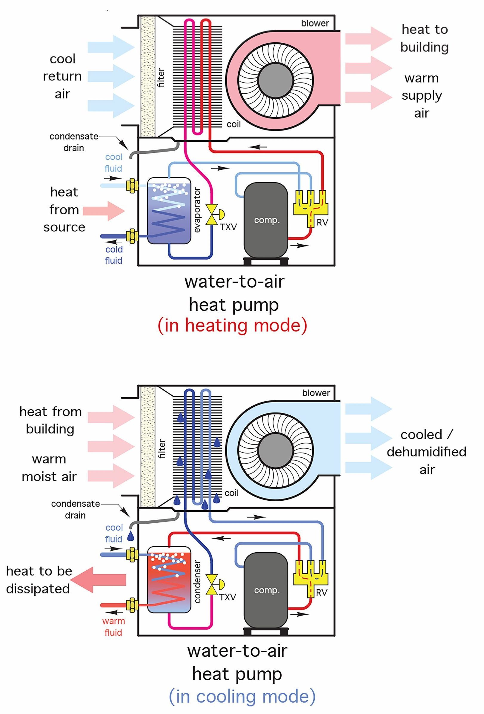
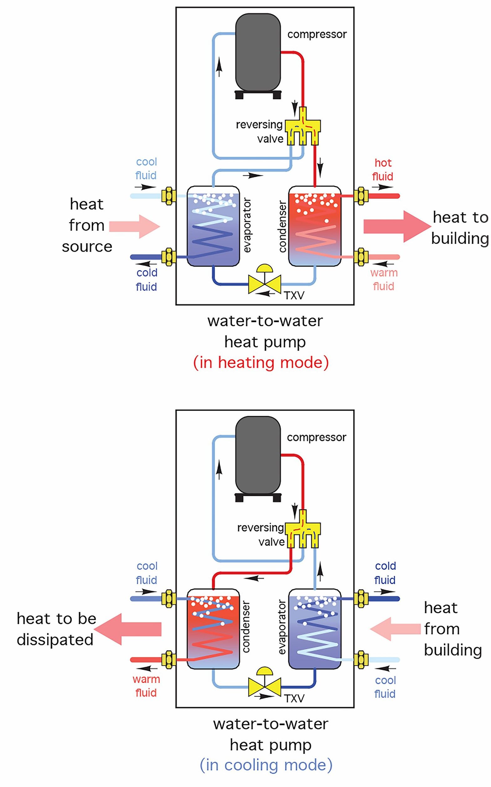
The biggest boon to the industry came in the 1970s with the invention of heat-fusible, high-density polyethylene (HDPE) piping. This material, along with improved trenching and joining methods, saw ground-source heat exchangers emerge as a viable component of water-to-water heat pumps. Today, high-cost energy, the use of reliable HDPE and PeX tubing for earth loops, and the availability of proven, reliable engineered design have fostered the rise in ground-source heat pump installations across Canada and many other countries. Low temperature radiant heating distribution systems are a perfect match for ground-source water-to-water heat pumps, while water-to-air heat pumps can utilize ducted forced-air systems as a media for cooling and heating.
Open-Loop Systems
Water drawn from open sources such as lakes, pond and wells can be circulated through the piping that collects heat when it acts as an evaporator or that dissipates heat when it is used as a condenser. The temperature of water that lies at the deepest points in a pond or lake, even those that freeze over in winter, doesn’t fluctuate by more than a couple of degrees over the year, and so is a good heat medium. Deep wells (those over 25 feet in depth) also share this attribute, which makes them well suited for use with water-to-air and water-to-water heat pumps. The two key issues that can have a detrimental effect of the system’s performance are the water’s quantity and quality.
A general conservative estimate of the amount of water required for sustained heat pump operation is 3 gallons per minute per ton at the evaporator or condenser. Therefore a 3-ton heat pump that may need to operate all day long would have to be capable of at least:
9 gallons per minute × 60 minutes per hour × 24 hours per day = 12,960 gallons per day
While most lakes and large ponds should be capable of supplying this amount of water, especially if the water is being returned to that source, a residential well may not. Also, a residential well’s primary purpose is usually to supply an adequate amount of domestic potable water for the home, and that factor combined with the heating/cooling water requirement often makes residential wells undersized and a non-viable option. Professionals such as hydrologists and well drillers should be consulted when investigating deep wells as an option.
After water from an open-loop system has passed through a heat pump, it is then returned to the same environment it was drawn from. The use of a private well may not be as much a contentious issue as would the use of “public” water, such as from a stream, lake or pond. Increasing environmental awareness may play a large part in the allowance or prohibition of such endeavours, and appropriate local, provincial and federal codes and laws must be consulted before forging ahead with an open-loop system. Also, the fact that the water may be returning to a private well may still have restrictions in place by groundwater legislation.
The quality of the water source is also a consideration to be dealt with. Deep wells are often high in TDS (total dissolved solids), silt, calcium and magnesium carbonates (hardness), sulphur compounds, manganese and iron, to mention a few constituents of groundwater. These can accumulate in the piping and heat exchangers and be the cause of high ongoing maintenance and a host of other possible problems. Manufacturers of heat pumps usually have literature that lists the possible contaminants found in open-loop systems, what their acceptable limits are and how to deal with them. Always consult manufacturers’ literature to avoid costly repairs and warranty issues.
Figure 7 below is representative of an open-loop system using a lake or pond as the water source.
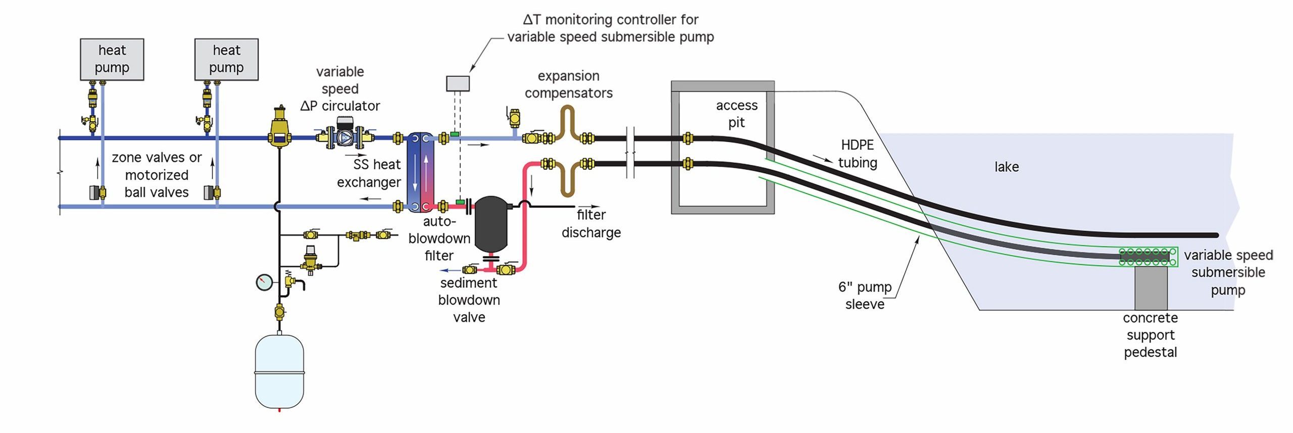
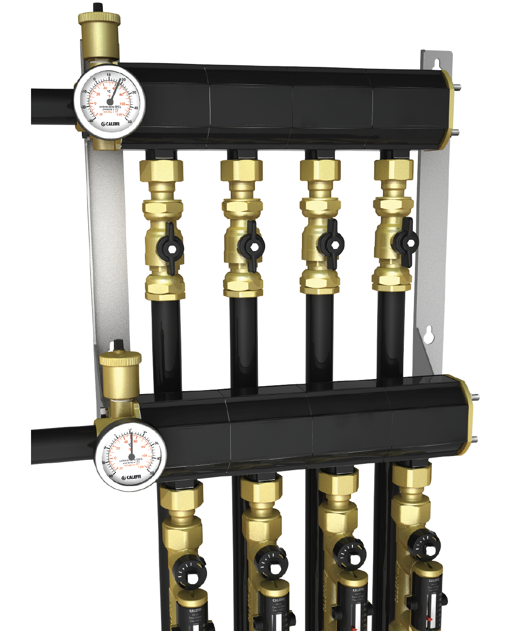
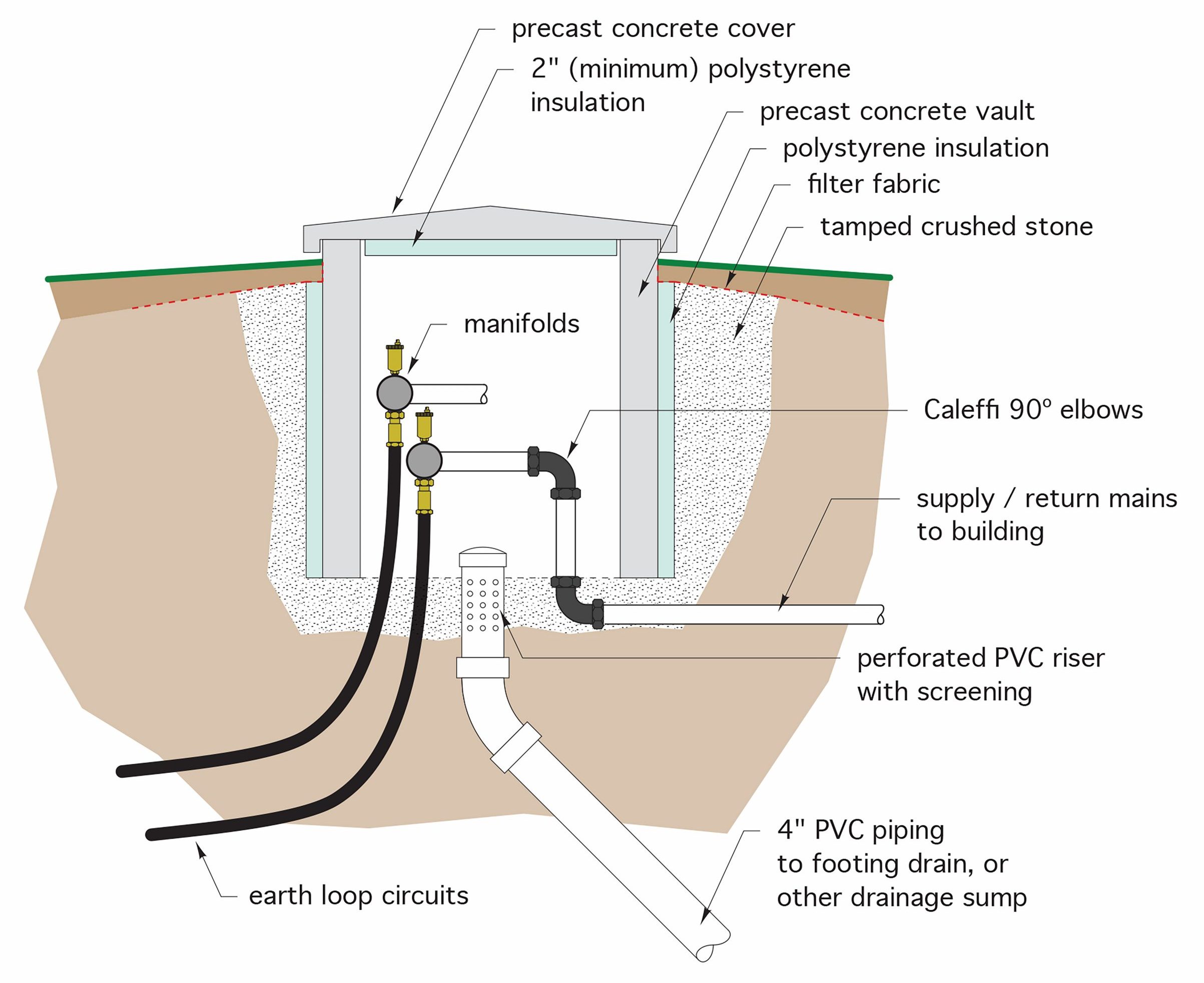
Figure 7 An open-loop system using a lake as the source
The pump is elevated above the lake bottom to prevent silt from being drawn into it. A sleeve is used around the intake line to allow the pump to be pulled and replaced for maintenance or repair, and terminates in a vault that is large enough to allow proper working space for the above. The submersible pump uses a variable speed controller that is set to provide a certain amount of temperature drop across the heat exchanger. If there is a large thermal demand on the system, indicated by a wider temperature differential, the pump’s speed increases to try to maintain the preset temperature drop. When the thermal demand lessens and the temperature differential narrows, the pump slows down.
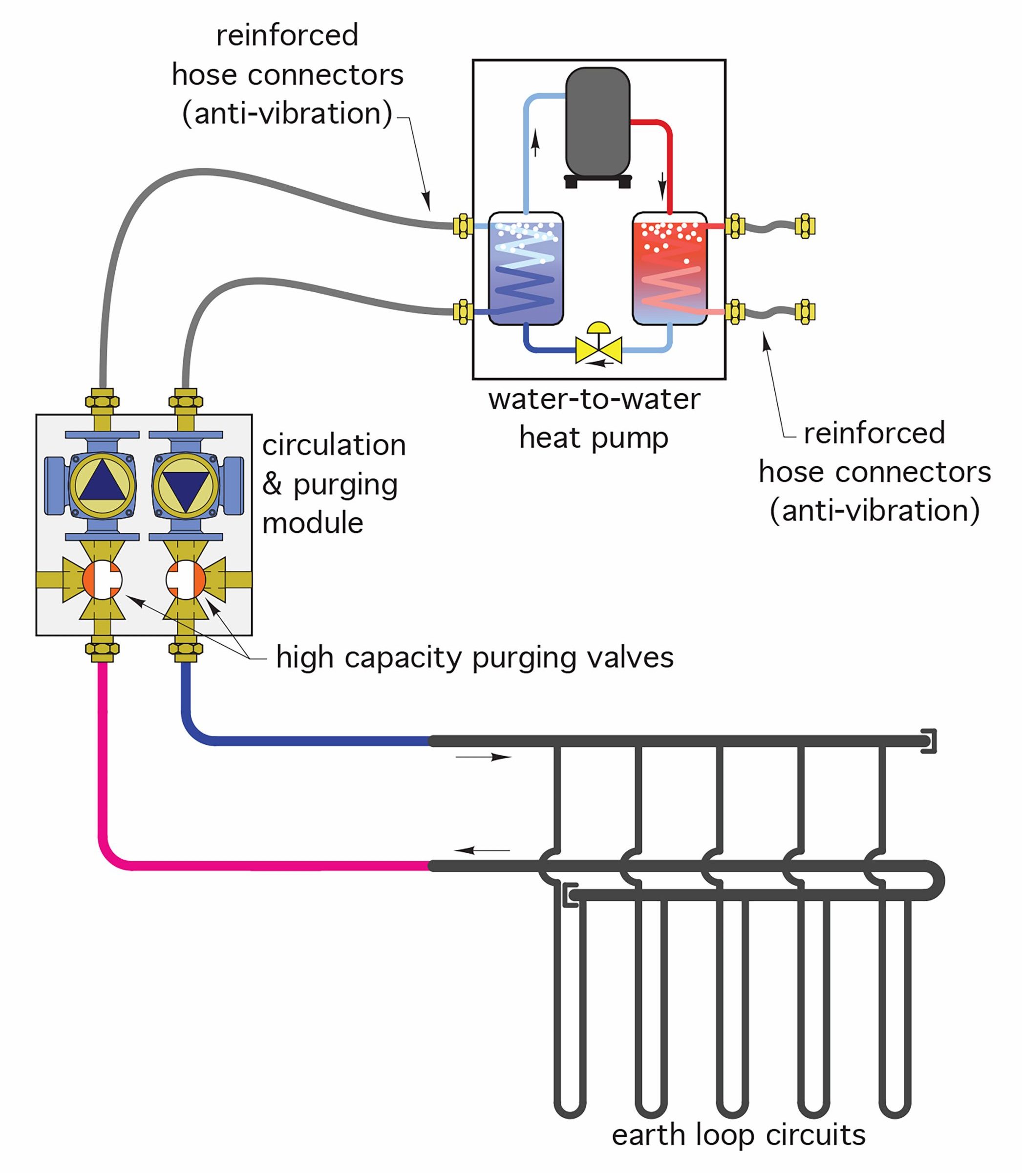
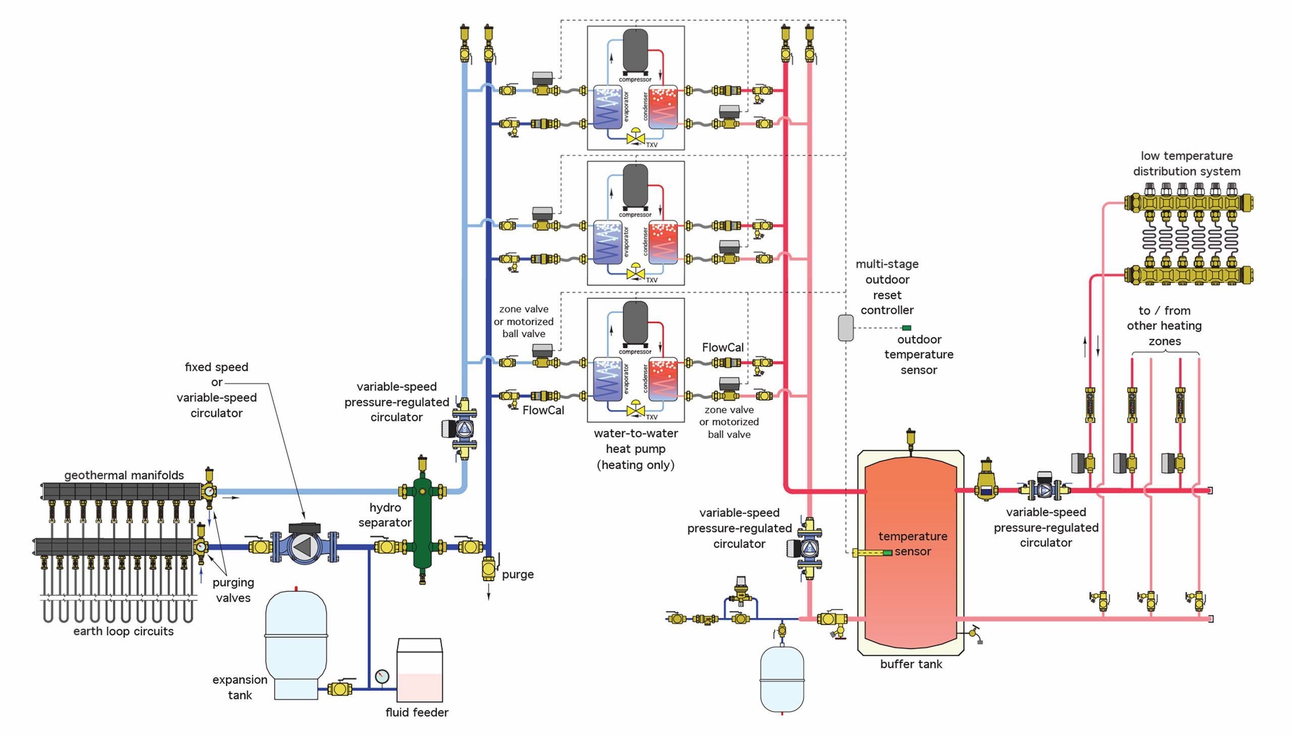
On the load side of the heat exchanger, flow through each heat pump is controlled by a zone or motorized valve that opens when the heat pump starts. A variable-speed, pressure-regulated circulator modulates flow between the heat exchanger and heat pumps. It will ramp up or down to provide only as much flow as is needed, thereby minimizing power requirements. Keeping pumping power usage as low as possible contributes to achieving higher COPs and EERs.
An open-loop well system is shown in Figure 8 below.
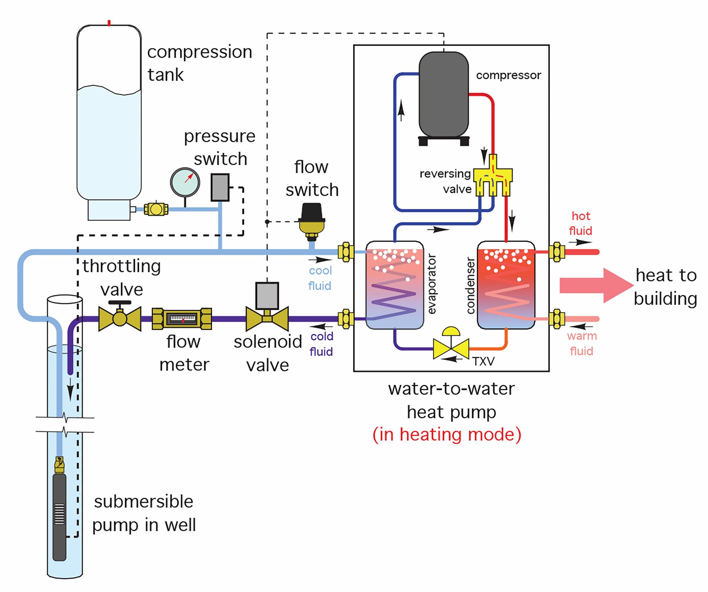
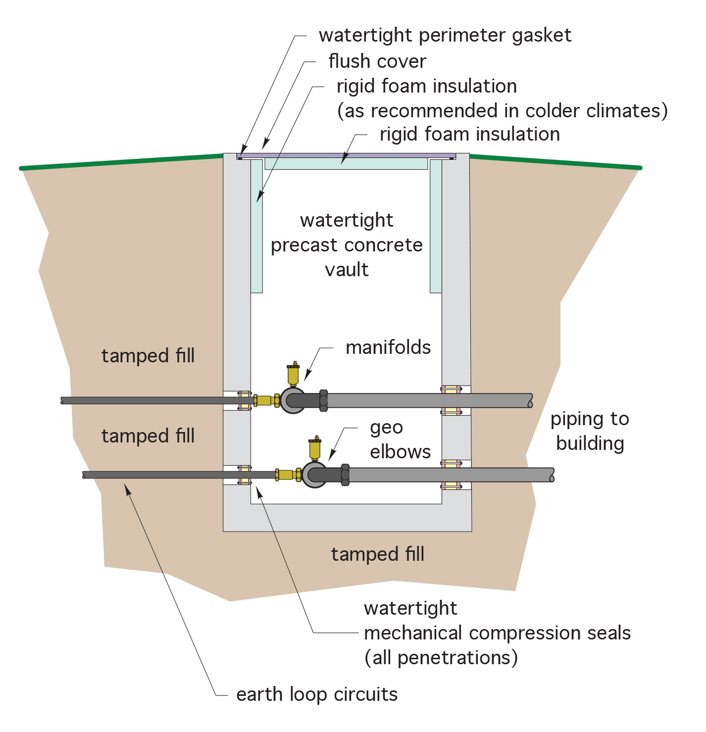
Figure 8 Open-loop well system
The water supply section of this system operates almost identically to that of a well system supplying only potable water to a house, in that it is operated by a pressure switch and a hydro-pneumatic tank. The pump comes on when the drop in pressure in the system causes the switch to close, and stays on until the pressure reaches its higher shutoff point. The building’s potable water system normally operates in this fashion. When water flow through the heat pump is needed, an electrically-operated solenoid valve opens and will close when the heat pump shuts off. A throttling valve and flow meter automatically adjust the flow rate through the heat pump, and a flow switch verifies that there is flow through the piping before the heat pump is allowed to operate.
Now complete Self-Test 2 and check your answers
Self-Test 2
- Which one of the following choices is associated with the heating efficiency of a heat pump?
- Annual fuel utilization efficiency (AFUE)
- Coefficient of performance (COP)
- Energy efficiency rating (EER)
- Steady state efficiency (SSE)
- Which one of the following choices is associated with the cooling efficiency of a heat pump?
- Annual fuel utilization efficiency (AFUE)
- Coefficient of performance (COP)
- Energy efficiency rating (EER)
- Steady state efficiency (SSE)
- Pick the response that most accurately completes the following statement: “Water-to-water heat pumps in heating mode work best when …..”
- The source temperature is highest and the load temperature is lowest
- The source temperature is lowest and the load temperature is lowest
- The source temperature is highest and the load temperature is highest
- The source temperature is lowest and the load temperature is highest
- What is one ton of cooling equivalent to?
- 2,000 btuh
- 7,500 btuh
- 12,000 btuh
- 36,000 btuh
- When determining a COP for the heating side of a heat pump, what are the units of measurement for the electrical energy input?
- Volts
- Amps
- Ohms
- Watts
- Using the formula , what would be the COP of a heat pump that is to deliver 24,000 btuh and its compressor is rated for 10 amps at 240 volts?
- 2.93
- 10
- 29.3
- 100
- Select the response that most accurately completes the following statement: “Water-to-water heat pumps in cooling mode work best when …..”
- The source temperature is lowest and the load temperature is highest
- The source temperature is highest and the load temperature is highest
- The source temperature is lowest and the load temperature is lowest
- The source temperature is highest and the load temperature is lowest
- What would be the EER of a heat pump that is to exchange 2 tons of cooling if the compressor is rated for 10 amps at 240 volts?
- 2.93
- 10
- 29.3
- 100
- In order to keep the EER of a heat pump in cooling mode as high as possible, what is the maximum suggested flow rate through either the evaporator or condenser?
- 1 GPM
- 2 GPM
- 3 GPM
- 4 GPM
- Why are earth (ground) loops considered to be a better heat pump source media than air?
- Because the ground is always hotter than outdoor air
- Because the ground is always colder than outdoor air
- Because the ground temperature is more consistent year-round as compared to air temperature year-round
- Because the ground temperature is less consistent year-round as compared to air temperature year-round
- What is the piing material most commonly used in ground-source heating?
- PeX
- HDPE
- Steel
- Copper
- According to conservative estimates, at least how many GPM per ton would be required in a water-to-water or water-to-air heat pump?
- 1
- 3
- 5
- 10
- When using open-loop systems, what are the characteristics of water that are of most concern?
- Quantity and quality
- Only the pH value
- Only the GPM
- Only the TDS
- In an open loop system using lake water as the source, what is used to allow periodic replacement of the pump?
- A sleeve on the intake line and a vault
- A sleeve on the return line
- A rowboat with oars
- A crane on a barge
- What two components of an open-loop well system are similar or identical to those found in a well system for a house?
- A throttling valve and TXV
- A solenoid valve and flow switch
- A torque arrestor and flow meter
- A hydro-pneumatic tank and pressure switch
Check your answers using the Self-Test Answer Keys in Appendix 1.
Media Attributions