Competency A3: Maintain Medical Gas Systems
Learning Task 2
Service Medical Gas Pipeline System
Medical gas systems require periodic maintenance to operate at peak efficiency and minimize unscheduled downtime. Inadequate maintenance can have a significant impact on energy consumption due to lower compression efficiency, gas leakage or pressure variability. It can also lead to high operating temperatures, poor moisture control and excessive contamination. Most problems are minor and can be corrected by simple adjustments, cleaning, replacing parts or eliminating adverse conditions.
All defective components must be replaced or repaired and operational defects immediately corrected upon observation, including flow obstructions and leaks. Repairs shall minimally conform to as-installed specifications. If circumstances prevent the repair or replacement from being performed immediately, and the defect has the potential to pose a health and/or safety risk, a risk assessment shall be made.
To protect the lives of patients, always notify the appropriate medical facility staff before performing any maintenance or service procedures. Display prominent notices indicating that maintenance is being carried out. If the repair or replacement of a defective component cannot be performed immediately, the component shall be tagged or labelled with at least the following information noted:
- the date;
- the problem;
- “Do Not Use” or limitations on use; and
- the name or signature of a qualified person.
The tag or label shall be removed by a qualified person or designate only on resolution of the defect.
Conducting routine preventive maintenance on a schedule is a useful way to perform necessary inspections and maintenance in a way that will minimize disruption to facility operations.
Maintain comprehensive records of maintenance activities, inspections, and any repairs performed on the medical gas systems. Accurate documentation aids in tracking the system’s performance and compliance with regulations.
Central cylinder supply systems
Regular and thorough maintenance of medical gas cylinder supply systems is essential to prevent disruptions in the delivery of medical gases, promote patient safety, and comply with regulatory requirements. It is advisable to follow manufacturer recommendations and industry standards for maintenance practices. Conduct routine visual inspections of the entire medical gas cylinder supply system. Connecting lines, or “pigtails”, from the gas cylinders to the manifold should be inspected and leak tested every six months. Since the cylinders containing the various gases run out and are replaced on a regular basis, these fittings and hoses get worn.
The manifold room typically has various cylinders of different kinds of gas lined up against the walls. Each kind of gas will come in color-coded cylinders, plainly labeled with their contents name, and have unique connectors to ensure no cross-connection of gases. All cylinders must be supported (usually chained) in a vertical position. Only gas cylinders and their accessories can be stored in rooms containing central supply systems or gas cylinders. Doors exiting from cylinder rooms shall have unobstructed, direct exit from supply system rooms via doors opening outward. The cylinder room must be temperature controlled, with adequately ventilation and an oxygen deficiency alarm.
Cylinder replacement
The exchanging of cylinders on an automatic changeover manifold is the most common interface that maintenance staff have with the medical gas supply system. When one of the banks of cylinders is depleted the manifold will automatically switched to the secondary bank of cylinders. An alarm is triggered and the empty cylinders must be replaced as soon as possible
Even though cylinders and manifold pigtails are fitted with gas specific connectors it is still important to confirm that the cylinder labels are in place and match gas required. being replaced. Labels shall not be defaced, altered, or removed, and connecting fittings must not be modified.
To replace empty cylinders:
- Enter cylinder storage room with caution, open door and air out the room.
- Identify which cylinders bank, left or right side, is empty.
- Close the cylinder valves on the empty cylinders.
- Using an appropriate wrench to loosen pigtail from empty cylinders releasing any residual pressure, then disconnect pigtails from the cylinder valve outlets.
Oxidizing gasses will have copper tubing pigtails which will be move difficult to remove - Install protective valve caps onto empty cylinders.
- Tag/identify empty cylinders.
- Use a cylinder cart to replace empty cylinders with full ones.
All cylinders both in use and stored (including empties) must be restrained
- When positioning and restraining new cylinders double check the gas identification labels.
- Remove the cylinder protective covers and store them were they can be easily located.
- Using a clean (lint free) cloth, wipe each cylinder valve outlet clean. Do not use your fingers.
- Standing to one side, “crack” each cylinder valve by briefly opening and closing to blow out any dust. Make sure they are pointing away from you and other personnel.
- Check the condition of the pigtail and replace any damaged ones.
- Connect the pigtails to the cylinder valve outlets and tighten the nut with an appropriate wrench
- When all of the cylinders are connected, very slowly open one cylinder valve and observe the bank pressure gauge, when the manifold is pressurized then all cylinder valves can be slowly opened fully.
- Leak test the pigtail connections
- Observe the manifold status indicators to confirm the empty bank is now indicating full cylinders on standby.
- Record the cylinder change out into the log
Mechanical supply systems
Compressor-based systems for medical air and instrument air as well as drying and filtration units, oxygen concentrators, medical vacuum systems, and AGSSs shall be inspected, maintained, and documented according to the manufacturer’s instructions at the recommended intervals. In many cases, it makes sense from efficiency and economic standpoints to maintain equipment more frequently than at the intervals recommended by manufacturers, which are primarily designed to protect equipment. Operators should review the equipment information and keep it handy for future reference.
Compressed air is dangerous and safety precautions must be observed in the use, service, and maintenance of compressed air and compressed air equipment. Lock-out and tag-out protocols should be followed. Completely vent the internal air pressure to the atmosphere before disassembling any subassemblies or components and before doing any work on compressed air equipment. To vent internal air pressure, follow the maintenance shutdown instructions. Never perform any maintenance functions while the unit is in operation. Before starting any maintenances procedures, disconnect and lockout all power to the package unit.
The following are suggested service schedules for typical medical air, instrument air, and medical vacuum compressor systems:
- Daily:
- check condensate in the receiver tank
- check the automatic drain on receivers
- check the oil level(s) and
- check the exhaust drain drip leg for presence of moisture/water
- Weekly:
- check the frequency of starts and the duration of the run period and compare with previous records and
- check the cut-in and cut-out pressure
- check operation of safety valve
- Monthly:
- check outdoor vacuum exhaust vents for obstruction (ice or debris on the screen)
- check belts and tension
- check flow through orifice of dew point sensor
- check outdoor medical air intake for obstruction
- Every 6 months:
- test all system functions and
- calibrate carbon monoxide transmitter
- replace intake and other system filters, if necessary
- Every 12 months:
- check dew point sensor accuracy
- change inlet filters
- change oil filters (oil lubricated pumps)
- change oil separator elements (oil lubricated pumps)
- change v-belts
- check inlet and discharge check valve operations
- check flex lines for wear or leaks
- check control panel contactors for wear
- check motor to pump coupler bushings and
- check and document vane wear (composite rotary vane-type pumps)
- Following manufacturer’s instructions:
- replace dew point and carbon monoxide transmitters
- change oil with specified type and grade
- lubricate the pump, motor, and bearings and
- replace piston rings.
Dryers
A compressed air dryer (Figure 1) should give long and trouble-free operation if the recommended preventative maintenance program is carried out. Ensure that the dryer and associated pre-filter(s) and after filter(s) are valve isolated and fully depressurized before attempting to remove or disassemble any subassemblies or components.
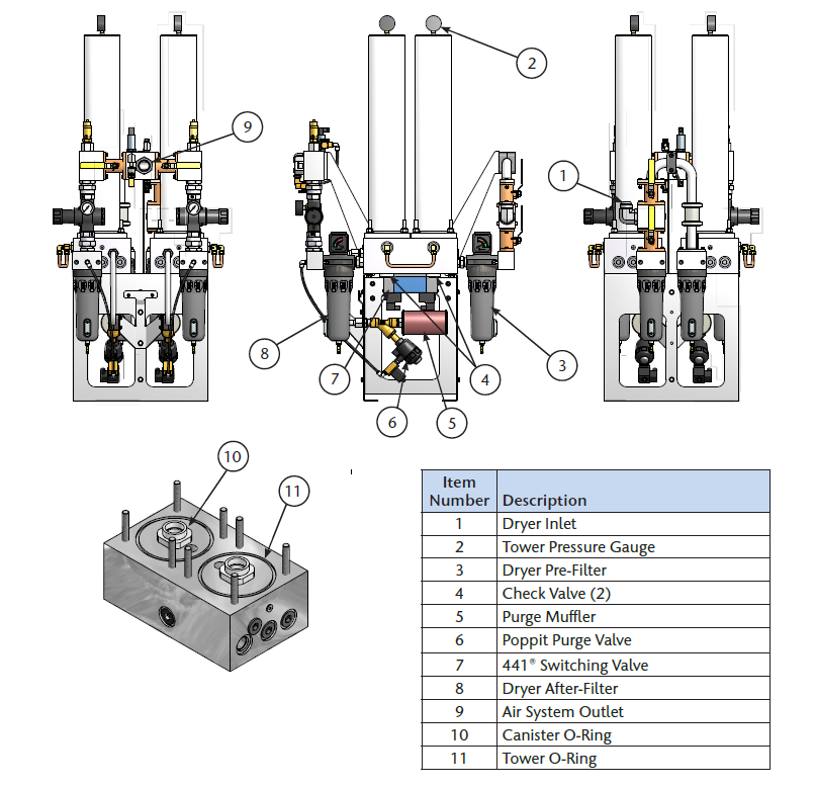
The following are suggested service schedules for typical drying and filtration units:
- daily checking of operation of the dryers and their filters for continued compliance with the manufacturer’s operating instructions;
- every 3 months;
- Clean the auto drain in the coalescing filter.
- Monitor the backpressure on the purging tower. If the gauge reads more than 0 psig (when purging), check the purge muffler for blockage and replace if necessary.
- every 6 months:
- test all system functions and
- clean the pre-filter strainer ball valve
- every 12 months:
- check or change all filters cartridges as per manufacturer’s instructions
- check or change exhaust mufflers/silencers as per manufacturer’s instructions
- check the automatic drain function in the coalescing filter as per manufacturer’s instructions
- check for air leakage of the outlet and purge check valves
- check for leakage at the inlet/exhaust control valve solenoids and
- check the inlet and exhaust valves/solenoids for wear.
- every 36 months:
- Change all annual parts.
- Change desiccant, check valves, shuttle valve(s), and purge valve(s).
Condensate drains
Condensate drains are possibly the least glamorous and most ignored component of a compressed air system. Nevertheless, there are very few things that can cause more trouble than having condensation accumulates in the supply unit. Condensate receiver tanks will usually have both a manual drain with sight glass and an electronic automatic drain. The condensate in the receiver tank must be checked daily to verify free flow and proper operation of the automatic drains. Electronic drains are usually either of the timer or demand type.
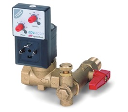
Timer drains use a timer to activates a valve to dump the condensation (Figure 2).
- You can adjust the drain cycles by setting the number of cycles per hour and the length of time the valve will stay open during each cycle. The theory is to set the timer for a long enough period to completely drain the condensation without setting it long enough to waste compressed air.
- The problem is that the amount of condensation will vary according to changes in the temperatures and relative humidity of the ambient environment. This means that the settings will have to be adjusted to compensate for climate and seasonal changes.
- Take the time to change the settings on your timer drains to match the changes in the ambient temperature and humidity.
- Avoid the temptation of using settings that will keep the valve open longer than necessary. This approach may get the condensation out of the system, but it sets up an automatic leak point for compressed air.
Electronic demand drains have electronic sensors that monitor the level of condensation within a reservoir (Figure 3). One sensor opens the outlet valve to dump the condensation when the housing registers as being full. Another sensor closes the outlet valve before completely draining the condensate to avoid wasting air.
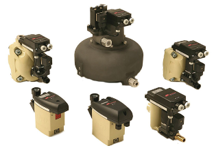
Maintaining electronic demand drains:
- Clean inlet filters
- Clean the sensors and the housing of an electronic drain regularly.
Compressor V-Belts
Check the belt tension monthly. Lock-out the main power and remove the belt guard. As shown in Figure 4, deflect each V-belt at the center of the drive span (position F) with a spring balance or tension meter at the manufactures tension force. Then check that the average deflections (position D) at the proper tension force are correct (usually approximately ¼ “).
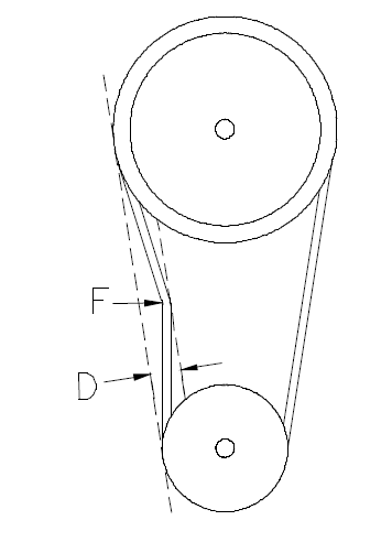
V-belts should be changed yearly under normal operating conditions. If any damage is found, V-belts should be replaced at once. To change the V-belts call the nearest distributor or follow this procedure:
- Remove the old belts:
- Remove the belt guard.
- Loosen the locking bolts securing the motor base.
- Adjust the belt tensioning adjustment rods on the motor base to loosen tension on belts.
- Remove the old belt(s).
- Check and clean:
- Check and clean all of the grooves of both the motor and compressor sheaves.
- Check the tightness of bolts on the sheave bushings.
- Installation of new belts:
- Confirm the belt type and length.
- Place the belt(s) into the grooves of both sheaves.
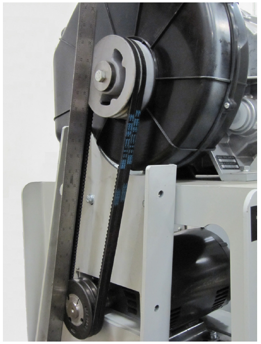
- Adjust the belt tensioning adjusting rods on the motor base until the proper tension and alignment is obtained. To check for correct alignment, place a straight edge on the faces of the two sheaves (Figure 5). Proper alignment is obtained when all the gaps between the straight edge and the sheaves are minimized and less than 1/8”.
- Replace the belt guards before operating the machine.
Line pressure regulators
As previously discussed, on parallel line pressure regulator arrangements one regulator is designated as the primary regulator with its pressure adjusted at normal distribution pressure. The secondary regulator is set at a pressure that is below the pipeline low-pressure alarm setting. During normal operation the assembly outlet pressure gauge will indicate pressure of the line regulator with the highest set-point and the secondary regulator will be in the closed position. As part of the required maintenance, the line regulator pressure settings must be alternated every six months and an operating record shall be kept. Below is an example of a manufacture’s instructions for the line pressure regulator adjustment on a cylinder changeover manifold. The manifold changeover, regulator droop and creep tests could also be tested at the same time.
Line pressure regulator adjustment:
- Open the right-side Line Regulator Isolation Valve and close the left-side Line Regulator Valve.
- Slightly open vent valve (less than ¼ turn) to create a small flow of gas through manifold.
- Using a wrench, loosen the right Line Regulator locknut.
- Turn the Right Line Regulator Adjusting Screw to achieve an appropriate output pressure gauge reading.
- Tighten the Right Line Regulator Lock Nut.
- Open left-side Line Regulator Isolation Valve and close the right-side Line Regulator Isolation Valve
- Using a wrench, loosen Line Regulator Locknut.
- Turn left-side Line Regulator Adjusting Screw to achieve an appropriate output pressure gauge reading.
- Tighten the left Line Regulator Lock Nut.
- Close Vent Valve.
- Open right-side Line Regulator Isolation Valve.
- Verify manifold operation.
Pipeline distribution system maintenance
If any part of the distribution system is breeched they must be tested and inspected as per the code installation standards. A system is breeched at point of pipeline intrusion by physical separation or by system component removal, replacement, or addition.
WARNING: To protect the lives of patients, always notify the appropriate medical facility staff before shutting off the supply of medical gas or vacuum through a shutoff valve. Do not close shutoff valves except in cases of emergency or maintenance
Shut-off valves
All shut-off valves should be tested annually for external leakage using oxygen compatible leak detector solution and/or suitable electronic leak detection equipment. Opportunities to test the main supply shut off valve or downstream isolating valves for tightness of shut-off are infrequent as it is impossible to shut-off valves while systems are in use. If the opportunity arises main supply shut-off valves, riser valves, branch valves, and any other service isolation valves should be operated to be checked, as seals can stick or leak.
Every 5 years zone valves must be checked for internal leakage by using a controlled standing pressure test to confirm tightness of shutoff. The standing pressure test entails; closing a valve and lowering the downstream pressure of the zone 20% of its normal value then observing any change in pressure.
The three-piece design of the shut-off valves makes changing the internal components of the ball valve easy. The valve bodies can be accessed by loosening all bolts and nuts and removing only one bolt, at this point the valve body can be swung out for servicing
Terminal units
Each terminal unit shall be tested annually for function, wear, mechanical performance, and flow resistance. During the performance test, a downward weight load similar to secondary equipment loads, and not in excess of the manufacturer’s recommended limit, shall be applied to the terminal unit to determine if the strain causes leakage.
If repairs are needed the “Latch Valve Assembly” can be removed without interrupting the service, but when servicing the “Rough-in Assembly” the supply pressure has to be shut off.
Zone alarm panels
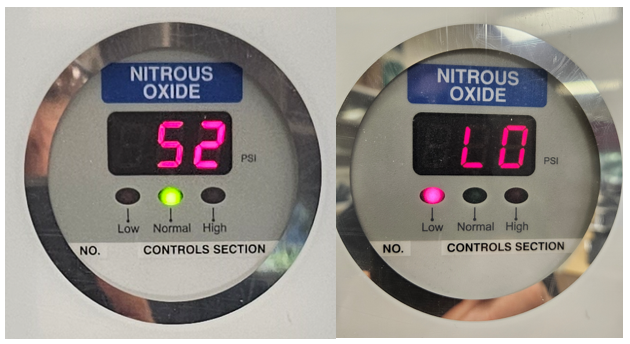
Annually the functionality of pressure sensors must be checked by applying low-pressure and low vacuum alarm simulations (Figure 6) to ensure alarm calibrations.
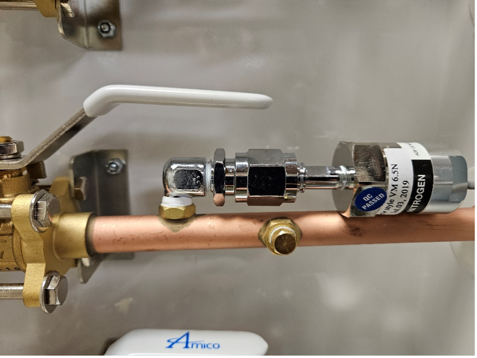
If an LED gas pressure readings is not accurate the sensor module should be checked (Figure 7). Ensure that the sensor module is properly connected to the DISS demand check-valve. Trace and check the wiring from the sensor module to the display module. If the sensor is faulty it can be removed at the DISS fitting from the check valve without shutting of the gas.
 Now complete Self-Test 2 and check your answers.
Self-Test 2
Self-Test 2
Media Attributions
- Figure 1. “Desiccant dryer components” – The source for this image is unknown. It is being used for non-commercial, educational purposes. To receive credit for this image, please reach out to the publisher.
- Figure 2. “Timed electric drain assembly” from Air Compressors Direct is used for educational purposes under the basis of fair dealing.
- Figure 3. “Selection of electronic demand drains” from Barton Associates, Inc. is used for educational purposes under the basis of fair dealing.
- Figure 4. “Belt tension” – The source for this image is unknown. It is being used for non-commercial, educational purposes. To receive credit for this image, please reach out to the publisher.
- Figure 5. “Checking belt alignment” – The source for this image is unknown. It is being used for non-commercial, educational purposes. To receive credit for this image, please reach out to the publisher.
- Figure 6. “Zone alarm pressure display” – The source for this image is unknown. It is being used for non-commercial, educational purposes. To receive credit for this image, please reach out to the publisher.
- Figure 7. “Gas specific pressure sensor assembly” – The source for this image is unknown. It is being used for non-commercial, educational purposes. To receive credit for this image, please reach out to the publisher.
Media Attributions
Figure 1. “Desiccant dryer components” image description: A labeled diagram displaying four different views of a desiccant dryer, highlighting its key components.
- Top Left: Shows the air system outlet (9), where dried air is delivered.
- Top Middle: Displays the tower pressure gauge (2), a visual indicator of tower pressure. The pre-filter (3) and after-filter (8) remove debris from incoming and outgoing air. Check valves (4) ensure unidirectional airflow. The purge muffler (5) reduces exhaust noise and filters out particulates like desiccant dust, while the poppet purge valve (6) controls the release of purge air. The 441 switching valve (7) toggles between the two filtered air lines.
- Top Right: Highlights the dryer inlet, where new air enters the system.
- Bottom Left: Shows the canister (10) and tower (11) o-rings, essential for maintaining an airtight seal. [Return to Figure 1]

