Competency A1: Install Medical Gas Systems
Learning Task 1
Describe Medical Gas Systems
Medical gases are used for patient care in health-care facilities, dental suites and laboratories. Gases manufactured for medical use may be identified by the acronym “USP,” which represents that their purity levels adhere to the United States Pharmacopeia standards. In Canada, medical gas piping systems are installed and commissioned to the CSA Z7396.1 Standard.
Advantages of pipe systems versus individual cylinders
There are a number of advantages to using medical gas pipelines rather than individual supply cylinders at the patient locations.
Advantages for patients:
- no distressing sight of oxygen cylinders at the bedside
- elimination of irritating noise from movement of cylinders
- protection from contamination during movement of cylinders
- uninterrupted and clean supply at desired location
Advantages for hospital staff:
- instant availability of gas at the terminal unit
- clean, safe and reliable delivery of gases
- continuous flow of gases when and where required
- minimal risk of accidents due to mishandling of cylinders
Advantages for hospital administrators:
- easy purchase of gases in bulk quantities
- more cost effective than purchasing and storing cylinders
- fewer breakages
- minimal damage to building due to handling of cylinders
Responsibilities
Patient safety is paramount in the design, installation, commissioning and operation of medical gas pipeline systems. The basic principles of safety are achieved by a team of professionals working together to provide a safe, convenient and cost-effective system. While these individuals strive toward a common goal, their responsibilities are quite different.
Owner
The owner of a medical gas system bears ultimate responsibility for the safe operation of a medical gas pipeline system. The owner and his design engineer must employ a trained installation contractor and a certified inspection company to perform and attest to final verification of the systems. The owner is also responsible to ensure that facility staff is properly trained. Facility personnel need to be aware of the nature of the systems in order to understand the purpose of warning and alarm systems and to participate in the safe operation of the systems. The owner should be familiar with the systems and be able to isolate these systems in the event of an emergency.
Installer
A medical gas installer is responsible for the proper installation, brazing and testing of medical gas and vacuum systems and pipeline distribution systems. They must possess the certification necessary to ensure that they have met the requirements of the CSA Z7396.1 Standard and are technically competent and experienced in the field of medical gas systems installation.
Third-party inspectors
A medical gas inspection agency is a certified company that is proficient and experienced in the installation, inspection, and verification of medical gas and vacuum systems. The inspector is responsible for: inspecting and testing all new piped medical gas systems, additions, renovations, temporary installations or repaired systems to ensure, by a documented procedure, that all applicable provisions of CSA Z7396.1 have been adhered to and system integrity has been achieved or maintained. Medical gas inspectors are required to maintain a logbook that contains records of site observations and test results. Test and inspection reports are also required as the project progresses. The inspector must personally witness the various tests and record and verify the results of any tests performed by the installer. The collected information then is assembled into a document for approval by the authority having jurisdiction.
Types of medical gases
The following supply gases and removal systems are frequently used in the health-care industries:
- oxygen
- nitrous oxide
- nitrogen
- medical air
Removal systems:
- medical vacuum
- anaesthetic gas scavenging systems
Some hospitals may have other gas piping systems, depending on the type of medical treatment the facility specializes in. Some of these gases are:
- carbon dioxide
- helium
- ethylene oxide
Uses and purpose:
- Oxygen (O2) is for patients requiring supplemental oxygen via a mask. This is accomplished by a large storage system of cryogenic liquid oxygen at the hospital, which is evaporated into a concentrated oxygen supply. Distribution pressures are usually around 380 kPa (55 psi). In small medical centres with a low patient capacity, oxygen is supplied by multiple standard cylinders or by mobile single cylinders.
- Nitrous oxide (N2O) is supplied to various surgical suites for anaesthetic functions during pre-operative procedures. Delivered to the hospital in standard tanks and supplied through the medical gas system. System pressures are around 380 kPa (55 psi).
- Nitrogen (N2) is typically used to power surgical tools such as bone saws and drills during various procedures. Pressures range around 1.2 MPa (175 psi) to the various locations within the facility and may be stored cryogenically. Nitrogen and instrument air are also referred to as medical support gases.
- Medical air (MedAir) is supplied by a special air compressor to patient-care areas using clean outside air. Pressures are maintained at around 380 kPa (55 psi). Medical air is only used for the application of human respiration and calibration of medical devices. Medial air is not to be used for nonpatient functions or to power pneumatic tools.
- Medical vacuum or suction (MedVac) is used, or piped, to virtually every patient location in a healthcare facility. The main application for suction is to assist in removing fluids or material from the patient. The fluid or material is collected at the “point of use” in vacuum vessel which prevents any substances from entering the pipeline. The system vacuum is usually supplied by various vacuum pump systems exhausting to the atmosphere. Continuous vacuum is maintained around 75 kPa (22 inches of mercury).
- Anaesthetic gas scavenging system (AGSS) is used to remove anaesthetic gas after it is exhaled from the patient. In operating rooms, it prevents the anaesthetic from leaking away from the patient or anaesthesia system and flooding the operating room.
- Carbon dioxide (CO2) is typically used to inflate or suspend tissues during surgery, and also used in laser surgeries. System pressures are maintained at about 380 kPa (55 psi).
- Helium (He) is used in MRI scanners that use magnetic fields and radio waves to form images of the body. Liquid helium (cryogenic) is used to cool down the superconductive magnet coils in MRI scanners to a temperature below –263°C (10 Kelvin).
- Ethylene oxide (CH2CH2O) is a highly flammable gas used to sterilize surgical instruments and other supplies.
Sources of medical gas
Medical gases are piped throughout the faculty from a central supply system. These systems must be designed to ensure there is no disruption of the medial gas supply. Depending on the volume and type of gas central supply systems can consist off:
- Bulk storage
- Cylinder manifolds
- Oxygen concentrators
- Compressors
Bulk sources of supply
Bulk supply systems are used where there is a high demand for medical gases within the facility. The advantage of bulk systems is that they allow convenient storage of large gas volumes within a small footprint on the property. Bulk storage can occur as a cryogenic liquid or a non-cryogenic high-pressure gas. Oxygen, nitrogen, nitrous oxide and carbon dioxide can be stored in bulk as gas, while cryogenic bulk vessels are restricted to oxygen and nitrogen due to the ability of these elements to liquefy.
Cryogenic bulk systems containing liquid oxygen and liquid nitrogen are very cost effective and convenient supply options for large installations. The bulk system equipment would include (Figure 1):
- storage tanks
- vaporizers
- control/monitoring panels
- pressure relief valves
- pressure regulating valves
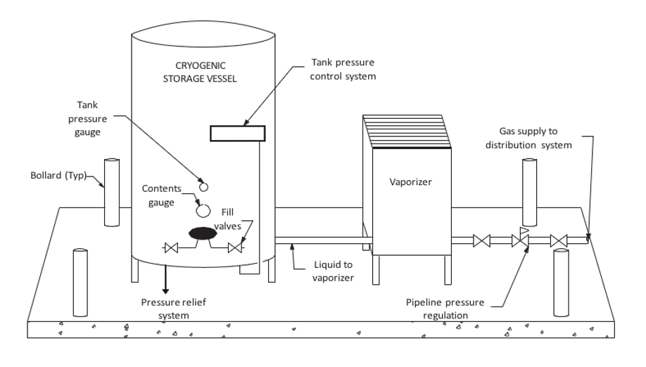
The liquid is converted to a gas with the use of vaporisers located near the storage tank. When a supply of gas is required in the facility, the liquid is drawn off and passed through a vaporizer to convert it into a gas, which is then piped to individual wards. It is very common to see these vaporisers covered in frost regardless of whether it is winter or summer. This condition is due to the heat required to facilitate the change of state (vaporization) before the gas enters the piping distribution system.
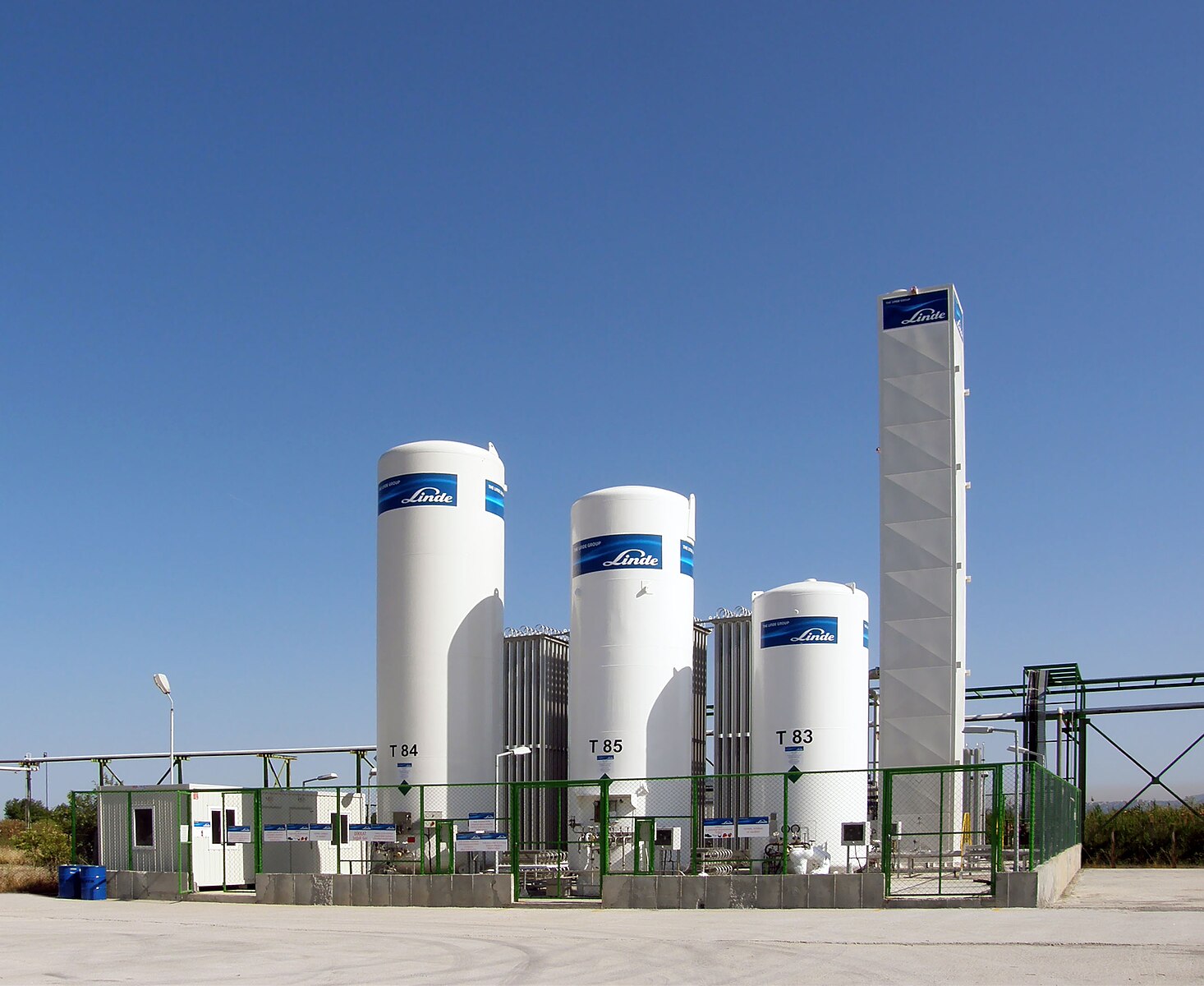
Bulk systems are usually located on a concrete pad in a fenced compound outside the building (Figure 2). The tanks are replenished by supply tanker trucks when required. Most regulating authorities require a professional engineer (P. Eng.) to assist in the design of the bulk storage facilities.
Bulk reserve systems
The typical bulk reserve system for the medical gas system provides a secondary source of product when the primary source is not functioning. The reserve system is designed to operate automatically when the main system fails. In larger facilities, the reserve system is a smaller liquid tank with its own vaporizers that provides gas flow to the system when the main tank runs empty or malfunctions. When the reserve system is activated, maintenance personnel are alerted that the primary supply is off-line. This is usually accomplished with audible and visible alarms.
Quite often a facility using a bulk supply system may have a cylinder bank acting as the reserve. Medical gas cylinders should be kept in a purpose-built cylinder storage.
Cylinder supply
When a medical facility does not consume enough gas to warrant the use of a bulk system, the gas piping systems are usually supplied by banks of gas cylinders connected to a supply manifold. Cylinder manifolds can also work to provide backup for bulk and mini-bulk installations. Medical gases are available in high pressure gas cylinders or liquid cryogenic cylinders. Liquid containers have limits in their rate of delivery based on the vaporization rate limitations of the cylinder. Manifolds can be set up in three possible configurations: cylinder by cylinder; liquid by liquid by cylinder; or liquid by cylinder by cylinder. Manifolds are typically configured as either auto changeover or simplex, depending on the complexity of the system.
A simplex manifold is a low-complexity system for connecting one bank of cylinders, typically as a reserve system for bulk supply systems to ensure a reliable supply.
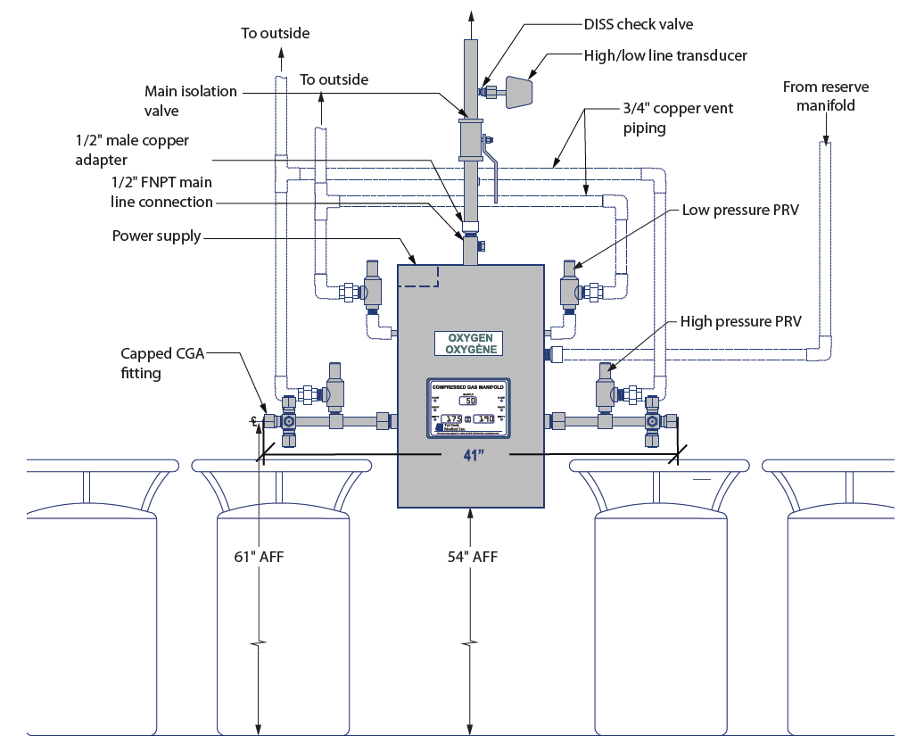
A changeover manifold (Figure 3) has two separate banks each with an average day’s supply of cylinders. One bank is designated as a primary source of gas while the other bank stands in reserve as a secondary. The pipeline will draw from the primary side until the volume available no longer meets the minimum requirement. When the primary bank has been sufficiently depleted, a switchover will occur and the reserve bank will now begin supplying the pipeline. This system creates an uninterrupted availability of medical gas for patients and allows time for the facility staff to replenish the exhausted bank with new cylinders. When this occurs, the reserve bank is now operating as the primary and the replenished bank is now acting as the reserve. This process will continue back and forth as the medical gas is consumed by the patients.
Medical gas cylinders contain two distinct parts:
- Storage vessel. Medical gas suppliers provide steel or aluminum cylinders in different sizes to suit the end users’ needs. These sizes are typically designated by a letter or number that identifies dimensions and storage volume.
- Cylinder valve. The valve outlet on each cylinder incorporates a thread pattern designed especially for use with a specific gas. The Compressed Gas Association (CGA) uses a number system to assign specific thread configurations for each specific gas valve profile. This assures the industry that all medical gases used in Canada will have exactly the same threaded connection for that specific gas. This requirement eliminates the potential for cross- connection when attaching equipment to a cylinder valve. The CGA thread patterns must match or the connection cannot be made. Figure 4 lists medical gases and their designated CGA connection numbers.
| Gas | CGA # |
|---|---|
| Oxygen | 540 |
| Air | 346 |
| Nitrogen | 580 |
| Carbon dioxide | 320 |
| Nitrous oxide | 326 |
Medical gas cylinders should be kept in a purpose-built cylinder storage room, so that the cylinders can be kept dry and in a clean condition. The medical gas cylinder storage room should:
- Allow cylinders to be stored under cover, preferably enclosed and not subjected to extremes of temperature.
- Have racks, chains, or other fastenings to secure all cylinders from falling, whether connected, unconnected, full, or empty.
- Be kept dry, clean and well ventilated (both top and bottom).
- Have good access for delivery vehicles and reasonably level floor areas.
- Be large enough to allow for segregation of full and empty cylinders and permit separation of different medical gases.
- Be totally separate from any non-medical cylinder storage areas.
- Be situated away from storage areas containing highly flammable liquids and other combustible materials and any sources of heat or ignition.
- Have warning notices posted prohibiting smoking within the vicinity of the storage room.
- Be secure enough to prevent theft and misuse.
Oxygen concentrators
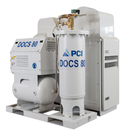
An oxygen concentrator unit (Figure 5) is an engineered assembly of components that operate to produce oxygen from ambient air by extraction of nitrogen. Normal air is 20.9% oxygen and 79% nitrogen. The concentration process passes air through a molecular sieve which captures the nitrogen and outputs 93 percent USP oxygen. Much like a sponge the sieve bed can only hold so much nitrogen so it is necessary to regenerate the sieve bed by venting or pulling the nitrogen off the sieve. The air source is typically a compressor or blower, which pushes the air into the sieve. A vent ,blower, or pump is used to remove nitrogen and recycle the sieve.
Besides direct supply to the hospital supply line, an on-site oxygen system can be designed to include the capacity to fill cylinders to provide backup, peak, and remote oxygen requirements.
An oxygen concentrator-based supply system must have at least three sources of supply (Figure 6). At least one of which must be an oxygen concentrator source of supply; and at least one shall be a portable cylinder source of supply (high pressure and/or liquid). The system must be able to deliver the total design flow with any two sources of supply out of service.
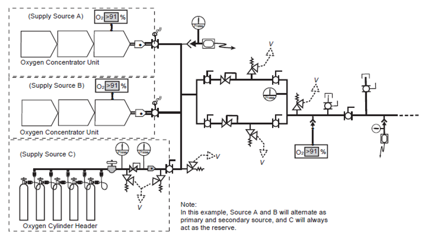
Each oxygen concentrator source of supply shall include two oxygen analyzers and controls so that each concentrator source of supply is automatically isolated if the oxygen concentration of the produced gas falls outside the 93 percent USP specification. 93% USP is defined as no less than 90% but no more then 96%.
Medical air compressors
Medical air is sometimes supplied in high-pressure cylinders, but due to the large volume of air that hospitals consume, on-site production is usually the most practical and economical method of supply. Medical air is manufactured on-site with sophisticated air compressor systems.
A medical compressed air system is made up of four major sections:
- compressors
- control systems and panel
- receiver
- purification
Compressor types
The definition of a medical air compressor is a compressor that is designed to exclude oil from the air stream and compression chamber and that does not, under normal operating conditions or due to any single fault, add toxic or flammable contaminants to the compressed air.
The CSA Z7396.1 Standard states that:
A compressor-based supply system for medical air shall consist of at least three sources of supply, at least one of which shall be a compressor source of supply and at least one of which shall be a cylinder source that acts as a reserve source. The supply system shall be such that the system design flow can be supplied with any two sources of supply out of service.
For the purposes of medical air production in Canada, acceptable technologies must use an oil-less or oil-free method of compression that contain no oil or grease in the compression chamber. This requirement limits the type of units that can be used, as oil is a very common way to reduce friction within a number of different compressor types. An oil less compressor contains no oil or grease within the machine. Oil-free compressors may contain oil in the running gear but are designed to prevent oil from reaching the compression chamber using a physical break such as a distance piece and vent.
Typical types of compressors used for medical air include (Figure 7) oil-free reciprocating, oil-less reciprocating, oil-less scroll, oil-free dry claw (tooth), oil-free screw, and liquid ring compressors. Some are direct driven and torque is transmitted from the motor to the pump through a shaft coupling, whereas others use a v-belt to connect the pump and motor pulleys.

There are pros and cons for each type of compressor and the designers will consult with the manufacture to determine which type is ideal for their facility. Some selection factors include: capacity, cost, efficiency, physical size, additional accessories, noise, maintenance.
As each type has different working principles it is important to consult the manufacture literature for the proper installation, operating and maintenance requirements.
Control systems and panels
Control panels manage the operation and protection of the system’s electrical components. These control panels contain all of the regular components used in industrial electric motor applications as well as a circuit of alarms. Latching relays and timers are used to control the sequence of operation. Many manufacturers are using more advanced control circuits that include solid-state circuit boards or PLCs (programmable logic controllers).
Receivers
Once the air has been compressed and leaves the chamber, it needs to be stored until it is required by the pipeline. This is accomplished by a receiver which, in essence, is a bulk steel storage tank that allows air to enter or exit under pressure. The receiver tanks vary in size and configuration and must be lined with a coating to prevent corrosion. These coatings are generally epoxy linings or galvanized coatings. Most medical air compressors produce a certain volume at approximately 100 to 125 psi (700 to 875 kPa) pressure (much less than what is stored in a high-pressure cylinder). The output is stored in the receiver.
Purification
Medical facilities rely on clean, dry compressed air for the medical air supply produced on-site. Air that has been compressed and stored is not considered medical grade until it has been dried and filtered. Since the intake for compressors is simply ambient air taken from outdoors, it could contain a high moisture content and carbon monoxide (CO). These impurities are transferred through the compression cycle and stored in the receiver. A dryer and filters are located downstream of the receiver to ensure that air being delivered to the pipeline does not contain a high dew point or CO. Although there are different technologies used in compressed medical air drying, Canada has moved almost exclusively to twin tower regenerating desiccant units.
The CSA Standard requires the installation of two identical banks of air treatment equipment piped in parallel and provided with valves to bypass either filter set for element replacement, maintenance and repair work while still treating medical compressed air through the other set.
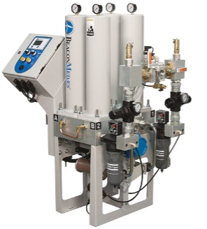
Figure 8 is a two-bank desiccant dryer package each bank consists of three stages within each bank:
- The 1st stage is a prime efficiency coalescing pre-filter rated for 0.01 microns, with filtered differential pressure gauge (element change indicator) and an electric solenoid auto drain valve controlled by the main control system. The pre-filter is the first line of defense against water contaminants and removes water aerosols before the gas enters the dryer. Liquids collected by the assembly’s filter cartridge(s) fall to the housing sump and are drained by a float drain.
- The 2nd stage is the heatless desiccant dryer towers. Each bank has two towers filled with desiccant that adsorbs moisture from the compressed airstream down to a dewpoint of -400C. One desiccant tower is always on-line in a drying cycle throughout normal dryer operation. The off-line tower is in a regeneration cycle for removal of the previously adsorbed moisture content.
- The 3rd stage are the after filters. The after-filter removes particulate matter such as desiccant fines that are carried over. To further remove any contaminants, the air passes through an optional activated carbon filter and an optional medical grade sterile filter.
Dew point and CO sensors
Quality monitoring for medical air revolves around measuring the dew point level and the amount of carbon monoxide (CO) present. While air drying and filtration are required, these two elements will not be completely removed and therefore need to be monitored to prevent them from going beyond the USP allowable amounts.
High levels of water vapour present in medical gases create two possible problems:
- The higher the concentration of water vapour, the more likely condensation will occur within the system. This could either interfere with sensitive instruments and apparatuses or cause corrosion within the system.
- High levels of water vapour, coupled with the warm conditions in hospitals, encourage the growth of bacteria, which could be harmful when inhaled by the patient.
Both dew point and CO are monitored by passing the medical air through sensors that relay the current levels to a visual display. The system initiates an alarm if the dew point or the CO are above the maximum level allowed under the USP requirement for medical air. Base mounted package units will typically include factory mounted, piped, and wired, sensors which will include remote alarm contacts.
Summary medical air supply system design:
There are basically four essentials to building a medical air system:
- The intake air location must never be contaminated by placing the medical compressed air systems in a poorly ventilated area
- The medical air must be available at all times, including in the event of a single fault failure.
- The air must be dry enough to ensure no liquid water can develop under any normal operating conditions
- Any contamination that the system can produce within itself under any operating conditions (e.g. particulates) must be removed (e.g. by filtration) before it reaches the patient.
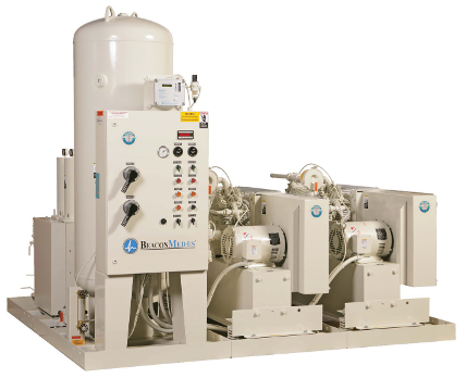
Complete manufacture pre-engineered medical air packages (Figure 9) provide all of the required safety devices for each machine type as well as all of the crucial elements of good compressed air systems design such as aftercoolers, drains and traps, dryers, and vibration isolation.
Vacuum (Suction) systems
Like medical air systems that are administered directly to patients, medical-surgical vacuum systems are also considered a life-support system and as such has specific requirements under CSA. All the system components shall be designed for full redundancy with the ability to provide continuous service in the event of a single source component failure and include additional provisions.
The CSA Z7396.1 Standard required that a supply system for vacuum shall consist of a minimum of three interconnected vacuum pumps and that the system shall be capable of supplying the design flow of the pipeline distribution system with any two sources of supply out of service.
A medical vacuum source system is a mechanical unit that through “on-site production” produces a negative pressure and takes air away from the patient. The fluid or material is collected at the “point of use” in a vacuum vessel which prevents any substances from entering the pipeline. The pipeline itself is not meant to capture or transport any fluids or solids. This service is used for a wide number of applications in a hospital and personal will often refer to it as suction.
While pressures in other medical piping systems are measured in psi or kPa, vacuum is commonly measured in inches mercury (in Hg) or millimeters mercury (mm Hg).
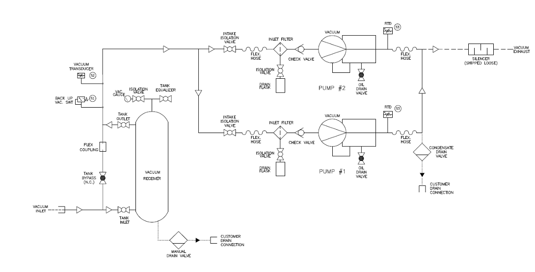
The diagram in Figure 10 shows the components of a vacuum system which include:
Vacuum pumps/compressors
A package medical vacuum system (Figure 11) does not look much different than a medical air system. Just like medical air the compressor is at the heart of the vacuum system. As the air flow is in the opposite direction, the unit is referred to as a pump rather than a compressor.
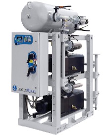
Just like medical air systems, different types of pumps can be used including rotary vane, reciprocating, liquid ring, rotary screw, rotary claw type, and multi-stage regenerative blowers. The choice of a specific type of vacuum pump depends on factors such as the required level of vacuum, the nature of medical procedures, and considerations for contamination prevention.
Medical vacuum pipeline systems are not intended to convey liquids, so the system must have a means to monitor or control the unintended entry of liquids into the piping. Any liquid drawn into the vacuum pump could cause a catastrophic failure.
Vacuum receiver
As vacuum can be stored as readily as compressed air, a receiver is connected to the suction of the vacuum pump. The primary function of the receiver is to act as a vacuum reservoir to accommodate sudden or unusually high system demands. Receivers used with vacuum pumps are similar to ones used with air, but they must be able to withstand the negative pressure rating to prevent the tank from collapsing. The receiver for a vacuum system is also used as a safeguard to protect the pumps from being exposed to liquids or solids that may be transported by the vacuum pipeline system.
Vacuum Filtration
The vacuum stream poses risks of biohazard exposure to healthcare staff, maintenance personnel, and the broader community if contaminants are released through the vacuum system exhaust. The healthcare facility is encouraged to make an assessment and determine if they consider the medical vacuum stream to be a biohazard and if bacteria filtration is necessary. To mitigate this risk, vacuum system suppliers may supply a HEPA filter with a minimum efficiency of 99.97% at the inlet of the vacuum pump. This measure helps limit the contamination of the vacuum equipment. Safety takes precedence during the maintenance of vacuum pump filters, as they should be regarded as biohazards. When changing these filters, it is imperative to use appropriate personal protective equipment (PPE) and adhere to proper handling precautions to ensure the well-being of those involved in the maintenance process.
Vacuum system controls
A minimum of three pumps are required by the CSA Standard, so the necessary controls for each pump will be centralized on one control panel. Most control panels will at minimum include the following:
- incoming power disconnects
- indicating lights for operation or alarm functions
- a pressure display
- individual control switches for each of the pumps in the system
The use of programmable logic controllers (PLC) and microprocessors is now relatively standard in newer systems, with the benefits largely revolving around the amount of information that can be shared with the maintenance staff.
Supply system pressure controls and safeties
The pressure in the pipeline between the supply source and patient must very accurately controlled to ensure that the medical gas and vacuum systems remain safe for patient use.
Table in Figure 12 shows the following nominal distribution pressures as listed in the CSA standard:
| Medical Gas | Nominal Pressure/vacuum |
|---|---|
| Oxygen | 345 kPa (50 psi) |
| Medical air | 345 kPa (50 psi) |
| Nitrous oxide | 345 kPa (50 psi) |
| Nitrogen/instrument air | 1100 kPa (160 psi) |
| Carbon dioxide | 500 kPa (70 psi) |
| Vacuum | -68 kPa (-20 in Hg) |
| AGAA | -40 kPa (-12 in Hg) |
Pressure regulators
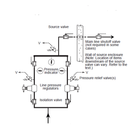
The gas pressure from each supply system, other than medical vacuum or AGSS, must be must be regulated before they can be used in a medical procedure. Regulation is accomplished by at least two line pressure regulators, installed in parallel to control the distribution pipeline pressure. Regulators are designed to control pressure; they do not measure or control flow unless they are equipped with devices such as a flowmeter specifically designed for such purposes.
The parallel assembly (Figure 13) enables for maintenance, repair, and replacement of any components on one arm without service interruption. The assembly provides single fault protection, automatic backup, overpressure protection, and appropriate regulator adjustments.
A dual-arm assembly includes the following in each arm:
- an inlet isolation valve;
- a line pressure regulator;
- a pressure indicator downstream of the line pressure regulator;
- a bleed valve downstream of the line pressure regulator;
- a pressure relief device installed downstream of the pressure regulator, with no valve intervening; and
- an outlet isolation valve.
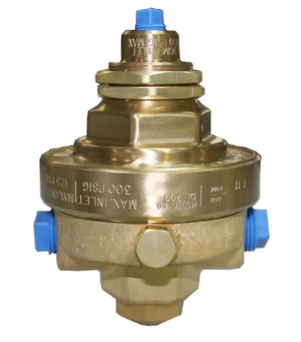
A dome loaded regulator (Figure 14) uses gas pressure to load the top of the sensing element rather than a spring. Dome loaded regulator are commonly used on change over manifolds to activate the appropriate cylinder bank header.
Pressure relief valve
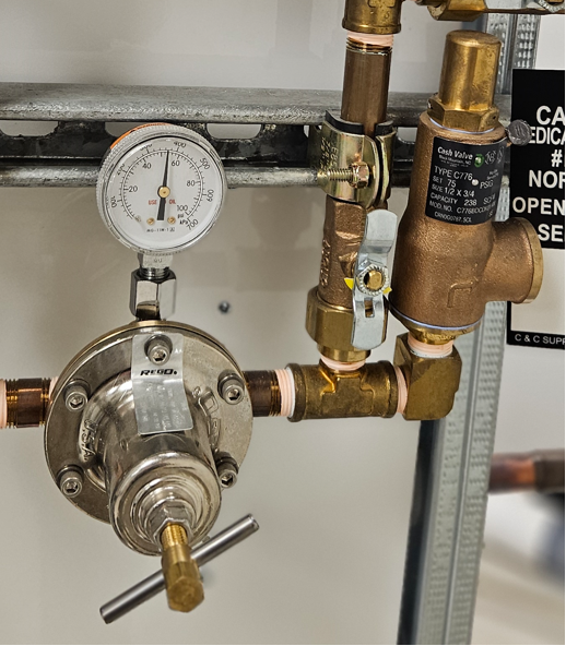
Pressure relief valves (Figure 15) are installed downstream of pressure regulators. They are used to prevent system overpressure due to regulator failure and cannot be isolated (by a shut-off valve) from pipeline or the pressure regulator to which they serve. They are set approximately 50% above nominal pipeline pressure but not exceeding 1360 kPa (200 psi). Pressure relief valves shall not discharge into locations that would create potential hazards. Therefore, for the most part, all relief valves are vented to outdoors and the vent discharge line can not be smaller than the relief valve outlet.
Medical gas cylinder manifolds
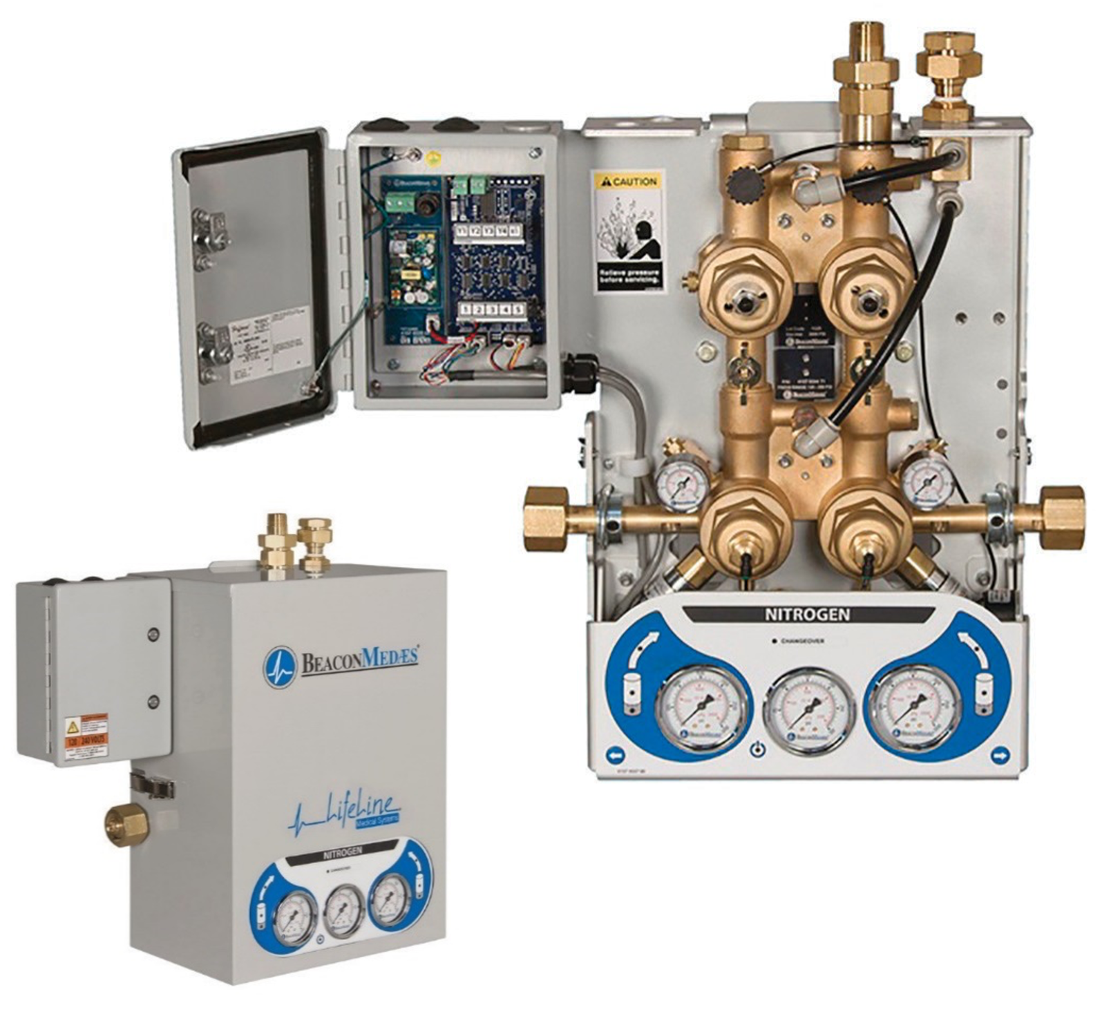
A gas cylinder changeover manifold assembly will have multiple regulators and relief valves built into it. The assembly will have additional regulators to first reduce the high cylinder pressure down to an intermediate pressure before going through the line pressure regulator.
Both changeover and simplex supply manifolds contain the following components:
- cylinder pigtails
- high-pressure header bar
- high pressure cylinder bank regulators(with gauges)
- pressure relief valve
A changeover manifold (Figure 16) will also include the following:
- changeover mechanism
- parallel line pressure regulators
- line pressure gauges/display
- method to identify that changeover has occurred
Medical Gas pipeline distribution system
The piped distribution system starts at, and includes, the source valves, warning systems, interconnecting piping and all other components up to and including the station terminal units.
Shut-off valves
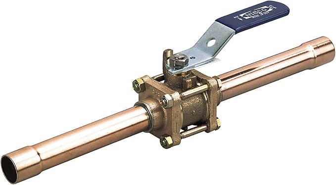
Shut-off valves installed in a medical gas pipeline serve two purposes: They control flow during maintenance procedures, and they are used to stop the flow of gas during an emergency. With the exception of vacuum systems which may use butterfly valves, all other medical piping systems must use quarter-turn ball valves. The shut-off valve is a three-piece design with a removable body for servicing without cutting or disassembling of lines. Valves are manufactured with copper extensions (pigtails)to facilitate brazing to the pipeline or with corrugated medical tubing (CMT) fittings. Valves can come with single (Figure 16) or double ¼” NPT-threaded ports cw installed plugs. The code does not specify whether single-port or double-port valve must be used; either can be used at the convenience of the facility. The ports are used to connect line pressure gauges and or sensors. During construction the ports can be used to purge the pipeline with nitrogen.
The CSA Z7396.1 Standard outlines where shut-off valves are required in the medical gas distribution network. They are identified by their pipeline location such as; source, main, riser, branch and zone valves. Each valve type corresponds to a different level of access and security to maintain the integrity of the systems.
The first valve of the system, called the main isolation valve, is located in-view directly at each source supply. When a source system is located remotely away from the building being served, CSA requires a main line valve also be installed in addition to the source valves. The closing of either the source and/or the main line valves will completely shut off the system from the entire building.
The piping system contains numerous lockout type service isolation valves that are required to isolate each riser and branch line from the distribution mains. They are typically installed in “out–of-view” locations known only by maintenance personnel. For this reason, they are only used for isolation purposes and are not for use in an emergency. The isolation valves located throughout the facility must be locked in the open position during normal operation to prevent the valve from accidentally being closed.
The next set of shut-off valves is located within individual zones or departments of the facility. Each type of medical gas that is piped to a specific area will have a zone valve that allows patient care personnel and first responders to isolate a specific gas in the event of an emergency or for authorized maintenance within a zone. There shall be a zone valve between any gas outlets and the upstream branch isolation valve that controls them. Zone valves shall not be installed in series. These zone valves are located in a flush-mounted box or enclosure. This enclosure, known as a zone valve box assembly, or ZVBA (Figure 18), is visible and accessible by department medical personnel. In an emergency the Plexiglas window on the front of the enclosure can be quickly removed by a hard pull of the ring in the center of the window, and the valve(s) can then be closed. The frame edge must be removed in order to replace the window.
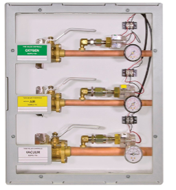
By way of the valve handle orientation, the valves can only be closed if the window is removed. This feature deters inadvertent valve closure, which could have serious consequences for patients relying on the gases.
Zone valve enclosures can contain up to seven valves, depending on the installation requirements. Some valve enclosures have an opening that exposes the chrome-plated portion of the valve, giving an aesthetically pleasing look. The connection with the pipeline is actually concealed behind the drywall so only the valve body and a portion of the connecting pipe are exposed.
The valves in the enclosure must not be equipped with a locking feature, and they must have labels identifying the direction flow, type of medical gas, and the locations it serves. There will also be a gauge indicating what the pressure is on the outlet side of the valve.
Medical gas terminal units
Industry professionals may refer to these as either the wall outlets or medical gas outlets. The NFPA standard uses the terms station outlets, or inlets for vacuum. The formal title used in the CSA Z7396.1 Standard is terminal units.
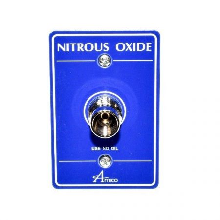
The terminal units (Figure 19) are provided at patient locations and allows the gas to be administered to the patient. The connections and faceplates are gas-specific, colour- identified and labelled with the name of the gas they supply. These identifiers are very important in preventing health-care staff from giving the wrong gas to a patient when attaching a device such as a flowmeter or a mask.
A complete terminal unit consists of two separate modules: the rough in assembly and the latch valve assembly (Figure 20). The latch valve assembly is pin indexed to the corresponding rough in assembly to avoid accidental cross connection.
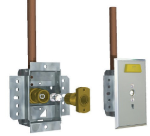
The terminal unit must contain two safety mechanisms (check valves) that will only allow the flow of gas if the proper conditions exist. These safety mechanisms are known as the primary and secondary check valves. The primary is located in the latch valve assembly and stops the flow of gas or allows gas to be delivered, depending on whether a gas-specific hose fitting is attached. The secondary is located in the rough-in section and will not allow the flow of gas if the primary section has been removed.
These assemblies include the following components:
- Rough-in assembly:
- the body that includes the secondary, spring loaded check and latch valve seals, which permits removal of the latch valve assembly for service without requiring the pipeline to shut down.
- A colour code labeled ½” [12.7 mm] OD copper tube is silver brazed into the body for external pipeline connection.
- Indexed latch valve assembly:
- the gas specific outlet connector with O-ring seal and internal primary check valve.
- the color-coded block, complete with body indexing pin
- gas specific faceplate
Flowmeters
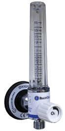
To measure and adjust flow, a special device called a flowmeter (Figure 21) is used in conjunction with a pressure regulator to deliver the necessary flow rate of gas for the prescribed treatment.
Alarms and sensors
Sensing/alarm systems provide a means to continuously monitor the medical gas source equipment and the operating pressures in the pipeline distribution system as well as in the critical-care areas of the facility.
To accomplish this, two main types of alarm warning systems are utilized for medical gas and vacuum systems:
- master alarm systems
- area alarm systems
Master alarm systems
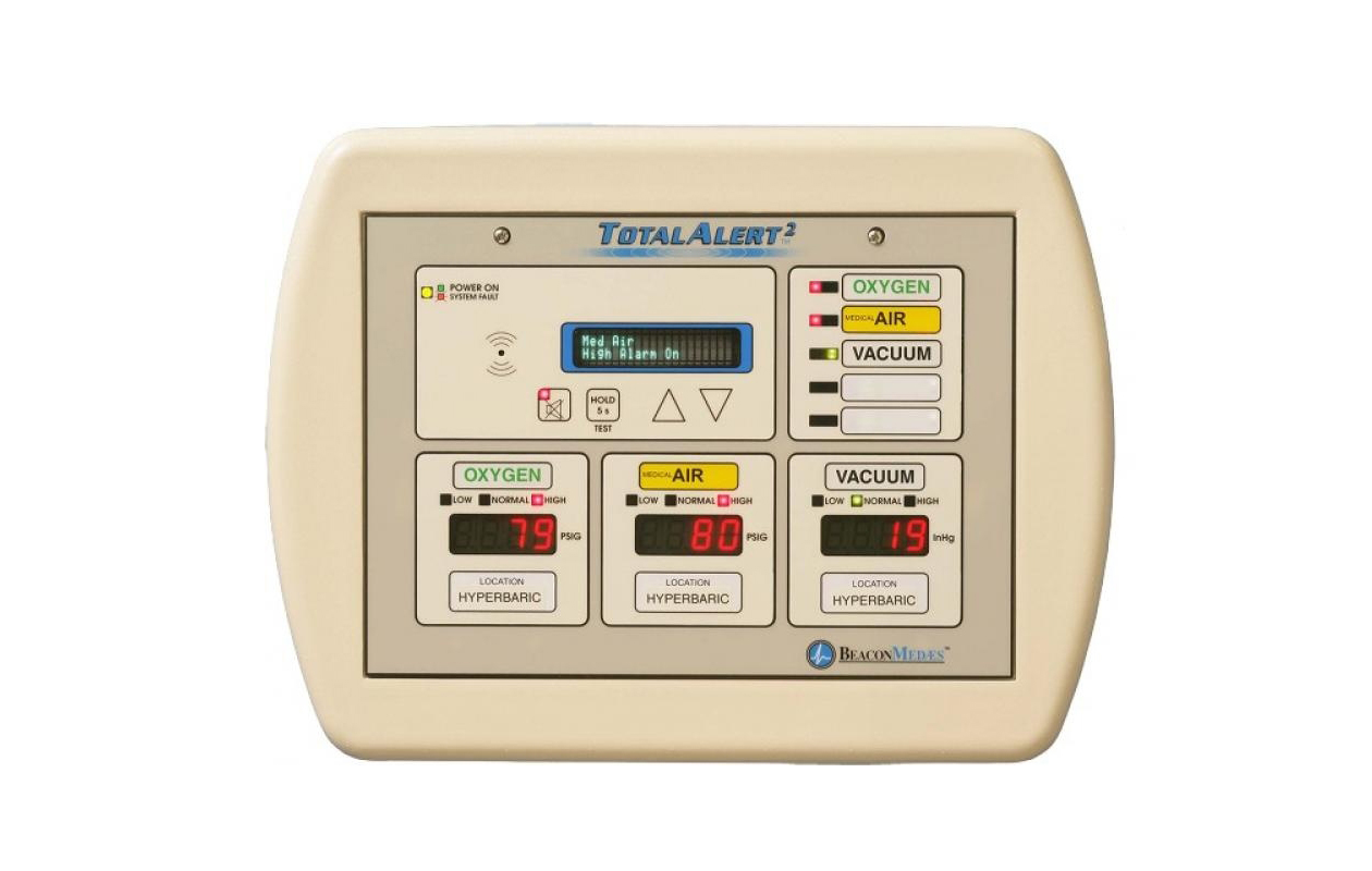
These systems monitor each medical gas and vacuum source system and the mainline operating pressures at the source of supply. Two master alarm warning panels (Figure 22) are required: one located in an area where it is continuously supervised during all operating hours of the health-care facility, and the other located in the department responsible for maintaining the medical gas and vacuum systems (e.g., facility management, engineering, maintenance shop, etc.).
Area alarm systems
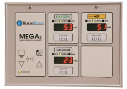
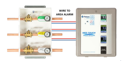
Area alarm systems (Figure 23) monitor the operating pressures in the pipeline distribution system for specific areas of the health-care facility. They are required for all life-support, critical- care and anaesthetizing locations. These alarm systems provide the medical staff with important information regarding the operation of the medical gas and vacuum pipeline to ensure they remain safe for patient use. Alarm panels are required to monitor pipeline pressure downstream of the zone valve box and must be located where they can be supervised by staff in the area they serve. The area alarm panels are NOT required to be monitored at the master alarm panels.
Pressure switches
Pressure in the pipelines is sensed by pressure switches or pressure transducers (Figure 24).
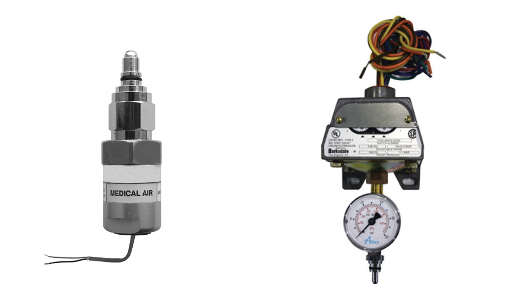
These pressure sensors connect to the distribution pipeline at critical alarm points and are wired back to the appropriate alarm panel (Figure 25). If the pressure in the pipeline exceeds or drops below a set value it will be annunciated at the alarm panel. The CSA Z7396.1 Standard provides a complete breakdown of all the required alarm points, but the facility operator may add their own extra points. It is important to note that there must not be any valves installed between the pipeline and the pressure sensor to prevent inaccurate reading due to accidental valve closure.
 Now complete Self-Test 1 and check your answers.
Self-Test 1
Self-Test 1
Media Attributions
- Figure 1. “Overview of a cryogenic bulk supply system” – The source for this image is unknown. It is being used for non-commercial, educational purposes. To receive credit for this image, please reach out to the publisher.
- Figure 2. “Bulk oxygen storage system“ by Engineer09 is licensed under a CC BY-SA 3.0 licence.
- Figure 3. “Liquid oxygen cylinders connected to automatic changeover manifold” – The source for this image is unknown. It is being used for non-commercial, educational purposes. To receive credit for this image, please reach out to the publisher.
- Figure 5. “Deployable Oxygen Concentration” from Kapp is used for educational purposes under the basis of fair dealing.
- Figure 6. “Oxygen concentrator central supply source with three sources” – The source for this image is unknown. It is being used for non-commercial, educational purposes. To receive credit for this image, please reach out to the publisher.
- Figure 7. Types of medical air compressors.
- “Oil-free reciprocating” from BeaconMedaes is used for educational purposes under the basis of fair dealing.
- “Oil-less reciprocating“ from BeaconMedaes is used for educational purposes under the basis of fair dealing.
- “Rotary scroll” by Camosun College is licensed under a CC BY 4.0 licence.
- “Dry claw” from PowerXSales is used for educational purposes under the basis of fair dealing.
- “Oil-free screw” by Camosun College is licensed under a CC BY 4.0 licence.
- “Liquid ring” from The Compressed Air Blog is used for educational purposes under the basis of fair dealing.
- Figure 8. “Medical air dryer package” from Sherman Engineering is used for educational purposes under the basis of fair dealing.
- Figure 9. “Medical air package unit” from BeaconMedaes is used for educational purposes under the basis of fair dealing.
- Figure 10. “Vacuum system components” – The source for this image is unknown. It is being used for non-commercial, educational purposes. To receive credit for this image, please reach out to the publisher.
- Figure 11. “Packaged medical vacuum pump and receiver system” from BeaconMedaes is used for educational purposes under the basis of fair dealing.
- Figure 13. “Parallel line pressure regulators” – The source for this image is unknown. It is being used for non-commercial, educational purposes. To receive credit for this image, please reach out to the publisher.
- Figure 14. “Dome loaded regulator” from Medical Testing Solutions is used for educational purposes under the basis of fair dealing.
- Figure 15. “Pressure relief valve monitoring a line pressure regulator” – The source for this image is unknown. It is being used for non-commercial, educational purposes. To receive credit for this image, please reach out to the publisher.
- Figure 16. “Pressure relief valve monitoring a line pressure regulator” from BeaconMedaes is used for educational purposes under the basis of fair dealing.
- Figure 17. “Three-piece ball valve (single port)” from NIBCO INC. is used for educational purposes under the basis of fair dealing.
- Figure 18. “Zone valve box” from Air Liquide Healthcare Canada is used for educational purposes under the basis of fair dealing.
- Figure 19. “Nitrous Oxide terminal unit” from Broward A&C Medical Gas Specialists is used for educational purposes under the basis of fair dealing.
- Figure 20. “Rough-in body with check valve disassembled (left), bayonet styled (PISS) latch valve and trim plate installed (right)” from MetalRedes is used for educational purposes under the basis of fair dealing.
- Figure 21. “Oxygen flowmeter” from BeaconMedaes is used for educational purposes under the basis of fair dealing.
- Figure 22. “Master alarm panel” from BeaconMedaes is used for educational purposes under the basis of fair dealing.
- Figure 23. “Area alarm panel” from Medical Testing Solutions is used for educational purposes under the basis of fair dealing.
- Figure 24. Pressure sensors.
- “Pressure Transducer (left)” from Amico Corporation is used for educational purposes under the basis of fair dealing.
- “Pressure Switch with gauge (right)” from Medical Testing Solutions is used for educational purposes under the basis of fair dealing.
- Figure 25. “Zone valve transducers wired to area alarm” from Pattons Medical is used for educational purposes under the basis of fair dealing.
Image Descriptions
Figure 3. “Liquid oxygen cylinders connected to automatic changeover manifold” image description: A labeled diagram illustrating the main components of an automatic medical oxygen changeover system, including oxygen tanks, changeover control box, distribution piping, and operating and safety controls.
- Oxygen Tanks: An oxygen tank is connected via piping to each side of the Changeover Control Box. Additional oxygen tanks are also available.
- Changeover Control Box: This control unit monitors the system and indicates when a changeover from the primary to the secondary oxygen bank has occurred. It typically features status lights to signal the switch, and many units also include an audible alarm to alert operators. Some changeover boxes may also have a manual reset function.
- Distribution Piping: The system includes supply piping for the oxygen and vent piping for safely venting gas from the pressure relief devices to the atmosphere. All distribution piping is required to be ASTM B819 approved.
- Operating and Safety Controls:
- High and Low Pressure Relief Valves (PRVs): These valves protect the system by maintaining safe pressure levels within the oxygen supply.
- High/Low Line Transducer: This device continuously monitors and adjusts the system the desired pressure.
- Standards and Safety Codes:
- DISS (Diameter Index Safety System): This system ensures that only compatible medical gas equipment is connected, preventing the risk of improper connections.
- CGA (Compressed Gas Association): The system follows CGA standards to ensure safety and compliance with industry regulations related to compressed gas use. [Return to Figure 3]
Figure 6. “Oxygen concentrator central supply source with three sources” image description: A labeled diagram of an oxygen concentrator-based supply system, featuring three sources of supply, distribution piping, and key operating and safety controls.
- Sources of Supply:
- The system is supported by two oxygen concentrator units and one bank of cylinders for continuous supply.
- Isolation and Monitoring:
- Isolation Valves are strategically placed throughout the system to allow for isolation of supply lines when necessary for maintenance or emergency procedures.
- Pressure Gauges are installed at key points to monitor and display the pressure levels within the system.
- Safety Features:
- Vented Pressure Relief Devices are integrated into the system to protect against overpressure conditions. These devices safely vent excess oxygen to the outdoors, preventing potential system failure or hazardous conditions.
DISS ports will be installed along the piping for collection of samples. [Return to Figure 6]
Figure 10. “Vacuum system components” image description: A labeled diagram illustrating the components of the vacuum system, including pumps/compressors, filter locations, a receiver, and key controls.
In this example, two vacuum pumps operate in parallel to maintain the required vacuum pressure within the medical vacuum piping, ensuring continuous and reliable operation.
- Filters are strategically located upstream of each pump’s inlet, establishing that only clean, filtered air enters the pumps, preventing contamination and maintaining desired system performance.
- The vacuum receiver serves as a storage unit, temporarily holding air extracted from the facility until a vacuum demand arises, helping to stabilize the system’s pressure during intermittent usage.
- Essential control components include:
- Isolation valves, which enable safe and efficient maintenance.
- Flexible connectors, which protect the piping from stresses caused by movement or vibrations.
- Drain valves, which allow for easy removal of any accumulated condensate or debris. [Return to Figure 10]

