Competency A1: Install Medical Gas Systems
Learning Task 4
Install Equipment for Medical Gas Systems
Medical gas systems require specialized equipment for the supply of different types of gases such as: Medical air, Vacuum, Oxygen, Nitrogen, CO2, and Nitrous oxide.
Regardless of whether a building is being newly constructed or a renovation is planned, it is important to be familiar with all documents, which specify the minimum system requirements and the minimum training standards required for medical gas installers, inspectors and verifiers. When all of these resources are utilized, there is a much greater likelihood that facilities will be constructed and maintained for the greatest patient safety.
Codes and regulations
Medical gas installers should be familiar with the standards that define the proper installation of medical gas equipment. The following are important industry trade groups that have helped to establish and support the codes that are necessary to design and construct safe medical gas pipeline systems:
- CSA Group
- National Fire Protection Association
- American Society of Plumbing Engineers
- Medical Gas Professional Healthcare Organization
Each of these groups has contributed to the development of formalized guidelines for the construction and maintenance of medical gas piping systems and medical gas testing and certification. When dealing with medical gas systems and equipment manufacturers, CSA Z7396.1 and NFPA 99 are the most important documents to reference.
Jurisdictional requirements
Although CSA Z7396.1 and NFPA 99 are the codes of reference for medical gas installations in North America, the local authority having jurisdiction (AHJ) may have established certain requirements that must be complied with while installing systems in their area. These requirements are published to enforce the construction of medical gas systems to higher performance thresholds than the code’s minimum requirements. As an installer, it is your responsibility to be aware of these jurisdictional requirements and to exercise them in your project.
Tools and equipment
A medical gas installer will require certain specialized tools and equipment when installing and testing the system. Such tools and equipment may include:
- copper fittings, cleaned for oxygen service as per the CSA Standard
- pipe thread compound approved for use with oxygen
- brazing rod
- tubing cutters
- deburring tool
- non-shedding abrasive cleaning pads
- oxygen analyzer (can be used by installers as well as verifiers)
- low-pressure nitrogen purge alarm with regulator
- nitrogen flowmeters
- oxygen-safe leak detector solution
- spray bottle (for leak detector)
- pipe labels
- valve tags
- fittings and adapters for outlets/inlets from different manufacturers
Source supply equipment installation
Many of the installation criteria for mechanical supply package units (compressors, vacuum pump, oxygen concentrators) are similar:
- The condition of the system should be carefully inspected upon delivery. Any indication of damage by the carrier should be noted on the delivery receipt, especially if the system will not be immediately uncrated and installed.
- Modules may remain in their shipping containers until ready to be installed. If any of the modules are to be stored prior to installation, they must be protected from the elements to prevent rust and deterioration.
- DO NOT REMOVE the protective covers from the inlet and discharge connection ports of the modules until they are ready for connecting to the facility’s pipeline distribution system
- Keep all packing in place around the dew point sensor and CO sensor during installation to minimize damage.
- For service accessibility it is recommended that there is a minimum of 60 cm (2 ft) clearance around the system and 90 cm (3 ft) of clearance in front of the control panel. As well as a vertical distance of 36” above the unit for ventilation and maintenance.
- Ensure that the site where the system will be installed has a source of electrical power and that power is of the correct electrical specification as per the design of the system.
- The system should be leveled and placed on a concrete pad that is suitable to sustain the weight of the system. If a raised concrete pad is used, the base must not overhang the concrete pad.
- The unit base must be securely bolted using all mounting holes provided in the base.
- The unit may have shipping spacers under the compressor/motor base which will need to be removed after the unit is secured.
- A method to drain away moisture is necessary. If a gravity drain is not available, a connection to a drain is necessary.
- Install in a well-ventilated and clean location with ample drainage
- Vibration during shipment can loosen electrical terminals, fuse inserts and mechanical connections. Tighten as necessary.
Supply equipment piping
The CSA Z7396.1 Standard states that the intake, exhaust and system piping for each medical air compressor, medical vacuum pump or other vibrating equipment must be isolated from vibration.
Isolation from vibration is achieved by the proper selection of resilient devices to be placed between the pump base and the building structure. Isolation is further accomplished by placing isolators between the compressor and the floor, flexible connections on all piping from the compressor and spring-type hangers on the piping around the compressor for a distance of about 6 m (20 ft.). Base mounted package units will usually have the compressor and motor isolators, and flex piping connectors as part of the package design. This enables the package frame base to be directly mounted to the floor and the piping connected directly to the supplied flex connectors. Seismic isolation may also be an option to order with the unit or engineered on site.
There shall be an auxiliary supply connection for each supply system of adequately sized to allow an auxiliary supply system to be connected to the pipeline. The auxiliary supply connection isolation valve shall be secured in the closed position when not in use, with a threaded inlet fitting capped or plugged for cleanliness.
The compressor air intake and vacuum exhaust pipelines must be sized as per the manufacture to account for length and fittings to ensure that no restriction of air flow that could cause compressor starvation.
The medial air compressor intake termination must be placed in an area free of toxic or hazardous contaminates. Unless an indoor source can be continuously monitored the air is taken from outside and the intake shall be located:
- at least 3 m (10 ft) from any door or operable window, and
- 15 m (50 ft) from any exhaust, such as vacuum pump discharge or sanitary vent exhaust, and
- at least 3 m (10 ft) above grade, turned down and screened to prevent contamination, and
- in a location where it will not draw in contamination from exhaust systems (e.g., contamination from furnaces, gasoline or diesel engines, vacuum systems, or scavenging systems)
Discharge piping from the medical air compressor source of supply shall be routed in such a way that it is not normally subjected to a temperature lower than 10°C above the produced medical air dew point.
The vacuum exhaust line is piped away from the vacuum pump discharge to the outside atmosphere. The exhaust outlet is typically located:
- at least 10 m (30 ft) from any door or operable window, and
- 15 m (50 ft) from any mechanical air intake, and
- a minimum of 3 m (10 ft) above grade with the end of the exhaust typically turned downward and screened.
Supply Manifolds
Medical gas manifolds are designed to supply the pipeline system with a sufficient quantity of gas by any combination of cylinders and/or tanks. The typical manifold for medical gases (oxygen, nitrogen, CO2 or medical air) usually consists of a two-sided supply with automatic changeover between the empty and full side, and an additional third source for emergency supply.
If cylinder storage is used as either the primary or secondary source, the cylinders are located in the same enclosure and connect to the manifold using two main components (Figure 33):
- cylinder pigtails
- header bar
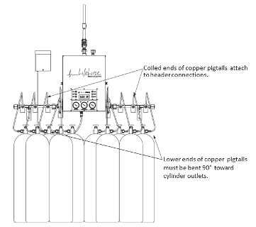
A cylinder pigtail connects a high-pressure cylinder to a header bar. This attachment device will have a CGA gas-specific nut and stem assembly at both ends to protect against cross-connection. The typical pigtail will be constructed of flexible copper or flexible braided stainless steel, depending on the type of gas and pressure. The cylinder end of the pigtail will include a check valve that will prohibit gas from other connected cylinders from escaping while it is disconnected from the cylinder. Also, if the cylinders on the bank do not have exactly the same pressure, the check valve will stop gas from transferring between the different cylinders.
The header bar assembly provides the means to connect multiple cylinders to a single regulator assembly located in the manifold enclosure. Each station will have a gas-specific CGA valve that matches the medical gas and the pigtail.
Section 5.3 of the CSA Z7396.1 Standard lists the requirements for the manifolds used for cylinder supply systems. The following is an overview of these requirements:
- Each cylinder bank, whether it is used as a primary or reserve source, shall be connected to a manifold that is equipped with a manifold pressure regulator, pressure indicator, pressure relief valve and shut-off valve.
- A non-return valve shall be installed at the manifold inlet or the manifold connection fitting of each flexible connector between the cylinder and the manifold.
- The flexible connector from each cylinder to the manifold shall be gas-specific for the intended purpose.
Manifold cabinet
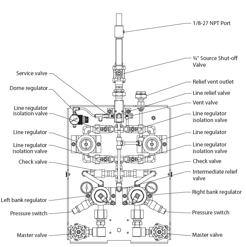
The header bar and pigtail assemblies with the appropriate number of connections will be supplied separate from the manifold assembly cabinet. In addition to the change over mechanism the manifold assembly will contain master source valves, pressure regulators, and pressure relief devices (PRD):
Medical gas manifold assemblies (Figure 34) provide two-stage pressure regulation by using two distinct single-stage regulators piped in series:
- Bank pressure regulator; The header bar assembly will be connected to a high pressure bank regulator that is responsible for reducing the cylinder pressure down to a predetermined intermediate level. There is a bank regulator provided for each bank of cylinders.
- Line pressure regulator; A single-stage, diaphragm-type regulator is used to reduce the manifold’s intermediate pressure to normal hospital line pressure. Two line regulators are provided, piped in parallel, to allow for isolation and service of one while the other is in use.
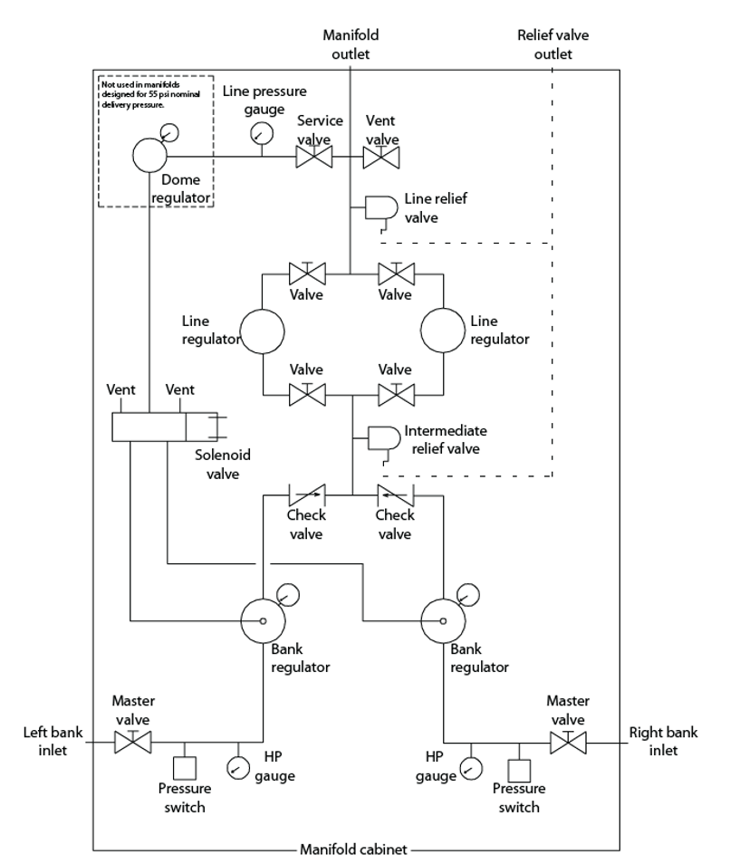
Relief valves are provided to prevent over-pressurization of the hospital piping system if a line regulator fails. These valves are set to relieve at a predetermined pressure that is higher than the intended delivery pressure but lower than the maximum rating of the pipeline. They operate using a spring and diaphragm assembly that has been calibrated to the proper level. Figure 35 is a schematic of the previously shown manifold assembly; notice the outlets of the relief valves are piped to a common relief valve port on top of the manifold. In this diagram the change over solenoid valve is also shown, which supplies gas pressure from the dome/pilot regulator to activate the appropriate bank regulator.
Note the parallel line pressure regulator arrangement. One regulator will be designated as the primary regulator with its pressure adjusted at normal distribution pressure. The secondary regulator shall be set at a pressure that is below the pipeline low-pressure alarm setting but not less than 241 kPa (35 psi).If the primary regulator fails to meet the flow and maintain pressure, the pipeline low pressure alarm will alert the qualified person. The secondary regulator will continue to deliver flow and maintain a pressure that supports medical equipment. During normal operation the secondary regulator will be held in the closed position therefore every six months the two line pressure regulator settings must be alternated to ensure both regulators are functioning.
Manifold installation
The manifold system will be shipped in multiple boxes containing; manifold cabinet, cabinet mounting bracket, header bar extensions, header support, and pigtails. The manufacture will provide detailed installation instructions for the manifold system that will cover:
- Cabinet wall mounting
- Connecting master valves and headers bars extensions to manifold cabinet
- Header support installation
- Securing cylinders
- Installing pigtails to the header bar connections and cylinders
- Outlet valve connection (The manifold system is often supplied with a separate source valve that will require installation to the manifold outlet.)
- Relief valve connection
- Power supply connection
- Remote alarm contact connections
The relief valve vent piping must be installed with appropriate materials and joining methods for the type of medical gas being vented. The relief valve outlet will typically be located on top of the manifold cabinet. Although the connection size will ½” NPT, the vent pipes must be sized in such a way that the vent line back pressure plus relief valve overpressure does not exceed 10% of setpoint.
For all compressed medical gases, except medical air and instrument air, the relief valve vent shall terminate outside of the building, away from flammable materials, and the vents shall be turned down and protected from the ingress of insects and debris. They shall be at least 3 m (10 ft) from any door, operable window, or ventilation intake and located so that discharges will not endanger passersby. When vents outlets locations are being planned, consideration should be given to the potential effects of prevailing winds or accumulated snow.
Shut-off valves
Section 8 of the CSA Z7396.1 Standard lists the requirements for shut-off valves. The following are the requirements related to the valve installations:
- All shut-off valves shall be quarter-turn ball valves.
- All shut-off valves shall be accessible for servicing.
- Service isolation valves shall be secured in the open position when a pipeline distribution system is in operation. During an extension, modification or maintenance of a pipeline system, the appropriate service isolation valves may be shut. When they are shut they shall be secured in the closed position.
- All service isolation valves shall be accessible to authorized personnel only.
- All service isolation valves shall be identified with the full gas service name and colour code.
- All service isolation valves shall be identified as to their purpose, area or section that they serve.
- All service isolation valves shall be identified whether the valve is normally open or normally closed and the identification label shall be secured to the valve or pipe and be readily visible.
- Zone valves shall not be installed in series.
- Zone valves shall not be installed closer than 2 m (6.5 ft.) to any fixed terminal unit.
- Zone valves shall be installed at a height where they can be operated by a person standing on the floor.
- Zone valve assemblies shall have a pressure indicator on the terminal unit side of the valve and be marked with a direction-of-flow arrow.
- Zone valves shall be enclosed in zone valve boxes.
- Zone valve boxes shall have covers or doors that can be secured in the closed position but that will allow quick access in case of emergency.
- Zone valve boxes shall be designed to prevent accumulation of gas and be permanently labelled as to the gases they control and the area they serve.
- Zone valve boxes shall be designed so that the shut-off valve handle prevents the closure of the box door or replacement of the cover when the valve is in the off position.
- In zone valve boxes with multiple shut-off valves, the valves shall be arranged in such a way that operation of one valve will not interfere with the proper operation of any other valves installed in the same service box.
- Zone valve boxes must be permanently labelled with a control label identifying the area of control, either on the box or the wall adjacent to the box (Figure 36).
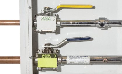
Valve box assemblies are shipped in packages that contain the; valve box recessed rough-in, valves, gauges, window, and frame assembly. Additional manufactures installation instructions may state:
- Allow sufficient space to accommodate the zone valve box. The rough-in of the zone valve box comes with a cardboard shield covering it’s front. The card-board shield will need to be removed to install the box but needs to be repositioned to protect the valves while the walls are being finished.
- Anchor the valve box to the structural frame supports so that it is level and the front edge will be flush with the finished wall. Box mounting height is suggested at 1.7 m (5.5 ft) from floor to top of finished box. Location should allow a clear view of gas readouts and access to valves during an emergency situation.
- Set valves into the valve box and slide plastic grommets as close to the center of the Zone Valve Box before brazing to avoid heat damage. Move grommets back to original location after piping has cooled. The Shutoff Valve handles should be installed to point downstream for pressurized gases.
- Wrap wet rags around the tube extensions next to the valves to prevent overheating and possible damage to the valve seals. Connect copper tubing to the valve extensions (outside the valve box) using brazing methods and materials in accordance with CSA Z7396.1. Once valve extensions are cool, remove rags.
- Alarm style zone valve will require completion of the wiring rough-in before the wall finishing.
- Install the correct gas identification label to the label holders in box. Mark location serviced by each valve in the space below the gas label.
- Test each system per CSA standard. After pressure test is finished replace cardboard shield until wall is finished to keep dust and debris out of box. Do not install gauges and sensors before the leak test as excessive pressure can damage them.
- After wall is finished remove cardboard shield (keep screws). Install Gauges and alarm sensors using Teflon tape or oxygen compatible pipe sealant.
- Pull ring to remove window from frame. Secure aluminum frame to box using screws from cardboard shield. Replace window into frame. Clean Window with soap and water, do not use strong solvents that will damage the window.
Alarms
Medical gas alarm systems monitor the status of the medical gas equipment and distribution systems. To properly evaluate the system, certain alarm-causing conditions (alarm points) must be monitored continuously by alarm sensors. The information is transmitted to an alarm panel, which provides audible and visual indicators to facility staff. Section 6 of the CSA Z7396.1 Standard lists the requirements for the monitoring of alarm systems. All master, area and local alarm warning systems used for medical gas and vacuum systems must include the following:
- Visual indicators that remain in alarm mode until the situation that has caused the alarm is resolved.
- A cancellable audible indication of each alarm condition that produces a sound with a minimum level of 70 dBA at 2 m (6.5 ft.).
- Re-initiation of the audible signal if another alarm condition occurs while the audible alarm is silenced.
- Labelling of each alarm panel stating its area of surveillance.
- Separate visual indicators for each condition being monitored.
- Labelling of each indicator indicating the condition monitored.
- Power for the master and area alarms is drawn from the life-safety branch of the emergency electrical system.
Location of alarm points
The CSA Z7396.1 Standard lists the required alarm points for both cylinder-based supply systems and mechanical-based supply systems. These are minimum requirements, and certain AHJs and design engineers could possibly require more. The following is a summary of some of the more common alarm points found in health-care facilities.
- Oxygen liquid supply:
- oxygen primary liquid level low
- oxygen secondary liquid supply in use
- oxygen secondary liquid low head pressure
- oxygen secondary liquid level low
- oxygen emergency reserve cylinders in use
- oxygen emergency reserve cylinders low
- oxygen line pressure low
- oxygen line pressure high
- Oxygen cylinder supply:
- oxygen reserve cylinders in use
- oxygen line pressure low
- oxygen line pressure high
- Nitrogen cylinder supply:
- nitrogen reserve cylinders in use
- nitrogen line pressure low
- nitrogen line pressure high
- Nitrous oxide cylinder supply:
- nitrous oxide reserve cylinders in use
- nitrous oxide line pressure low
- nitrous oxide line pressure high
- Medical air compressor:
- medical air lag compressor in use
- medical air high water level in receiver
- medical air receiver flooded
- medical air compressor low water shutdown
- medical air reserve cylinders in use
- medical air reserve cylinders low
- medical air high dew point
- medical air line pressure low
- medical air line pressure high
- Medical air dryer (desiccant):
- desiccant dryer switching failure
- desiccant dryer low outlet pressure
- Medical air dryer (refrigerated):
- refrigerated dryer high temperature
- refrigerated dryer power failure
- Medical vacuum system:
- vacuum pumps low oil shutdown
- vacuum pumps high temperature shutdown
- vacuum pumps maintenance required
- vacuum lag pump in use
- vacuum low
Alarm sensor installation
Every sensor is distinctly marked and color-coded based on the gas or vacuum it is monitoring. The sensor module incorporates a gas-specific Diameter Index Safety System (DISS) fitting, ensuring correct connection of the sensor to the corresponding gas. Each sensor undergoes factory calibration by a computer, aligning it precisely with the gas indicated on the sensor housing. In the event of incorrect connection to the designated gas display module, an error message will be promptly displayed.
Gauge and sensor will need to be installed into the appropriate pipeline ¼” NPT ports (Figure 37) after the pressure tests have been completed.
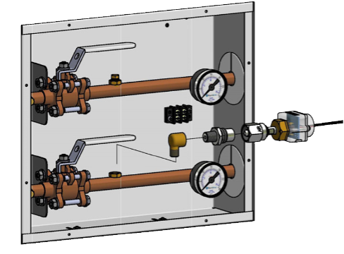
Check the manufacture manual for detailed instructions. Here are some general guidelines for the installation of sensors into an alarm zone valve box:
- Do not install gauges and sensors assembly before the leak test. Excessive pressure can damage the gauge and sensor.
- Remove sensor modules from shipping carton and locate the gas specific sensor module to be installed.
- Wrap threaded end of 90° elbow with teflon tape and insert into port. Tighten 90° elbow until opening faces away from valve for handle clearance.
- Verify the gas label on the valve piping is the same as the gas identification found on the DISS check valve.
- Install Check Valve into 90° elbow.
- Connect sensor with DISS fitting to the appropriate DISS check. Verify Gas ID labels match between the sensor and piping to ensure no cross connections occur.
Repeat this process for all sensors within alarm panel.
Terminal units
The CSA standard provides a distribution chart of suggested terminal unit locations; however, the health care facility can select the number and type of terminal units required based on their clinical practices.
Station outlets/inlets should be located at an appropriate height above the floor to prevent physical damage to connected equipment
Styles of connections
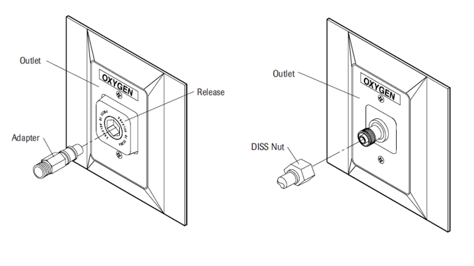
Terminal units are available with either Quick-connect or DISS outlets/inlets (Figure 38). Both methods are designed to ensure gas-specificity and can only accept compatible fittings. The main difference between these two options is that DISS is a threaded connection and quick connect adapters are a “push–and- lock” type of design. For either system once the connection is made, the primary valve within the terminal unit is opened, permitting gas to flow.
There are three different types of quick connect systems; Ohmeda Diamond, Puritan-Bennett or Chemetron. Only the matching system and corresponding gas type of adapters can be used with the Quick-Connect outlets
The DISS type of connections, comply with Compressed Gas Association Standard V-5 for medical gases at 200 psig (1400 kPa) or less. They a have a unique diameter of threaded connector for each type of gas.
Terminal unit installation
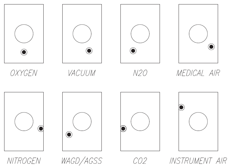
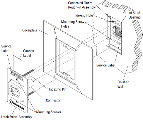
A complete terminal unit is made up to two separate components, the “Rough-in Assembly” and the “Latch-Valve Assembly”. The rough-in assembly (AKA Back-Body Assembly ) has a specific pin indexing arrangement (Figure 39) to prevent the wrong latch valve assembly from being plugged into the rough-in assembly.
The installation is completed in two stages of the building construction, rough-in and finishing. The following is an example of installation instructions for wall outlets, be sure to check the actual manufactures instructions:
Rough-in stage:
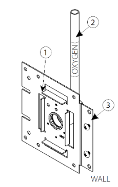
- Provide rigid mounting for rough-in assemblies (Figure 40) appropriate for wall construction. Rough-in assemblies must be mounted to a structural member (3). It is suggested that rough-in assemblies be installed with the outlet centerline approximately 1.5 m (5 ft) above the finished floor or as specified by the building plans. Position the front edge of the rough-in assembly (1) at the depth that will be flush with the finished wall surface.
- Connect the extension tube (pigtail) (2) to the piping system, making certain that piping is for the same service as labeled on the extension tube and mounting plate. The extension tube can be rotated a full 360 degrees for ease of connection to the facility gas piping. When brazing the pipe connection take extreme care not to apply heat to the check unit body.
- Ensure that the clear plastic dust cover over the rough-in assembly is securely in place until the latch-valve assembly can be installed, to protect the outlet from drywall compound or other contaminants.
- Perform standing pressure and cross connection tests per applicable standards. Inspect all joints for leaks.
Finishing stage:
- Select the service indexed and labeled latch valve assembly to match the correspondingly indexed and labeled concealed outlet rough-in assembly already installed.
- When installing the latch-valve assembly, remove the protective dust cover from the rough-in assembly and inspect for dirt or debris in the outlet body. Carefully clean out any contaminants.
- Align the indexing pin on the latch-valve assembly with the indexing hole in the rough-in assembly (Figure 41). The latch-valve mechanism should slide smoothly into the rough-in assembly. If it does not, inspect to verify that there has been no damage to the indexing pins. If the indexing pins are bent or damaged the gas specific characteristics of the outlet may be compromised. In this instance the entire latch-valve assembly should be replaced.
- The cover plate should be flush against the finished wall. The latch-valve assembly is secured with plated steel screws, alternately tighten the mounting screws until the cover plate is held snug against the finished wall. Do not overtighten the mounting screws, doing so may distort the valve assembly.
Pressure testing
The CSA Z7396.1 Standard requires installers to conduct two pressure tests for the detection of leaks when installing medical gas pipeline systems:
- A standing pressure test confirms for the installer’s own purposes that the work is of the required quality.
- A documented final leak test provides a record that the installation of the system meets the requirements of the CSA Standard.
In order to perform these tests, the installer should have the following equipment on-site:
- 0–100 psi (0–700 kPa) gauge (calibrated)
- 0–300 psi (0–2100 kPa) gauge (calibrated)
- 0–30″ Hg vacuum gauge (calibrated)
- a source of oil-free dry air or oil-free dry nitrogen
- gas-specific connection hoses
The full testing procedures are outlined in A-2, “Test and Commission Medical Gas Systems.”
 Now complete Self-Test 4 and check your answers.
Self-Test 4
Self-Test 4
Media Attributions
- Figure 33. “Medical gas pigtail and header bar configuration” – The source for this image is unknown. It is being used for non-commercial, educational purposes. To receive credit for this image, please reach out to the publisher.
- Figure 34. “Inside of Medical gas manifold assembly cabinet” – The source for this image is unknown. It is being used for non-commercial, educational purposes. To receive credit for this image, please reach out to the publisher.
- Figure 35. “Medical gas manifold piping diagram” – The source for this image is unknown. It is being used for non-commercial, educational purposes. To receive credit for this image, please reach out to the publisher.
- Figure 36. “Labels for zone valve control box” from Winona Heating & Ventilating is used for educational purposes under the basis of fair dealing.
- Figure 37. “Sensor installation” from BeaconMedaes is used for educational purposes under the basis of fair dealing.
- Figure 38. “Medical gas terminal units Quick-Connect type (left) and DISS type (right)” – The source for this image is unknown. It is being used for non-commercial, educational purposes. To receive credit for this image, please reach out to the publisher.
- Figure 39. “Example of a rough-in assembly pin index system” – The source for this image is unknown. It is being used for non-commercial, educational purposes. To receive credit for this image, please reach out to the publisher.
- Figure 40. “Terminal unit wall mounted rough-in assembly” is adapted from Amico is used for educational purposes under the basis of fair dealing.
- Figure 41. “Latch-valve assembly installation” – The source for this image is unknown. It is being used for non-commercial, educational purposes. To receive credit for this image, please reach out to the publisher.
Image Descriptions
Figure 34. “Inside of Medical gas manifold assembly cabinet” image description: A labeled diagram of a medical gas manifold system, showing various components involved in gas flow control and pressure regulation. Key features of the diagram include:
- Service valve and ¾” source shut-off valve for controlling gas input.
- Dome regulator and line regulators that help manage gas pressure.
- Isolation valves for shutting off different sections of the system.
- Check valves to prevent backflow.
- Intermediate relief valve and line relief valve for pressure relief.
- Pressure switches for monitoring system conditions.
- Master valves at the bottom for primary control.
- Left bank and right bank regulators, for dual gas supply banks. [Return to Figure 34]
Figure 39. “Example of a rough-in assembly pin index system” image description: A diagram showing a rough-in assembly pin index system. For each example, there is one large circle in the centre representing the connector and one smaller circle representing the pin.
- Oxygen: the pin is directly below the connector
- Vacuum: the pin is about 15 degrees to the lower right of the connector
- N2O: the pin is about 15 degrees lower left of the connector
- Medical air: the pin is about 30 degrees to the lower right of the connector
- Nitrogen: the pin is about 50 degrees to the lower right of the connector
- WAGD/AGSS: the pin is about 30 degrees to the lower left of the connector
- CO2: the pin is about 50 degrees to the lower left of the connector
- Instrument air: the pin is about 30 degrees to the upper left of the connector [Return to Figure 39]

