Competency B1: Select Regulators, Valves, and Valve Train Components
Learning Task 3
Describe Pressure Regulators
Pressures throughout the various gas piping systems varies greatly to accommodate the different system requirements and limitations. For example, the natural gas customer supply mains or propane storage containers will have high pressure to increase their volume capacity. Whereas the maximum allowable inlet pressure for gas appliances is typically only ½ psig, Pressure regulators are used throughout gas piping systems to maintain a desired reduced outlet downstream pressure while providing the required gas flow to satisfy the demand. Regulators are self-contained, self-operated control devices which use energy from the system to operate.
Other the following terms may vary in their usage for this textbook we will use the following definitions:
- Category – The name associated with regulators used to serve a specific purpose and or location
- Classification or Class – a term used to express pressure or volume limitations that may exit within a category.
- Type – a term used to identify various physical styles and designs. There are many regulator types that exist within a category to achieve different performance characteristics.
- SCFH – capacity; means standard cubic feet per hour of a gas at temperature of 70° F and a pressure of 14.7 PSIA.
- Servo or Pilot – a mechanism set in operation by another mechanism
Purpose
Gas pressure regulators have two main purposes:
- To reduce the supply pressure to a safe operating pressure for the building or connected appliance(s).
- To maintain a constant downstream pressure, regardless of changes in the gas flow or upstream pressure.
The regulators downstream pressure can typically be adjusted within a certain range to match the system requirements.
Some regulators may also provide overpressure protection to prevent gas pressure in the system from exceeding the rating of the system components.
Regulator Categories
There are four categories of pressure regulators as defined in the CSA B149.1 Natural Gas and Propane Installation Code:
- Service regulators
- Appliance regulators
- Line pressure regulators
- High pressure regulators
Service regulators
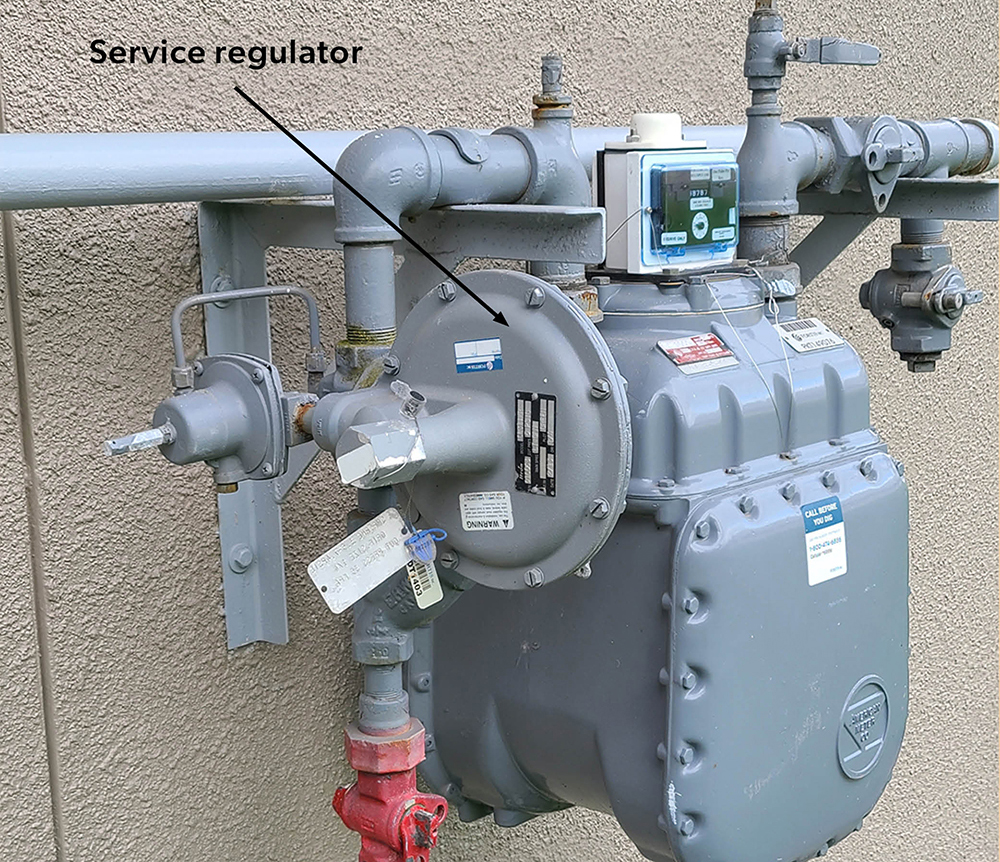
Service regulators are installed on a service line to reduce the gas pressure to the desired building pressure. The Natural gas meter sets are provided with a service regulator (Figure 14), which is installed by the gas utility rather than the gasfitter.
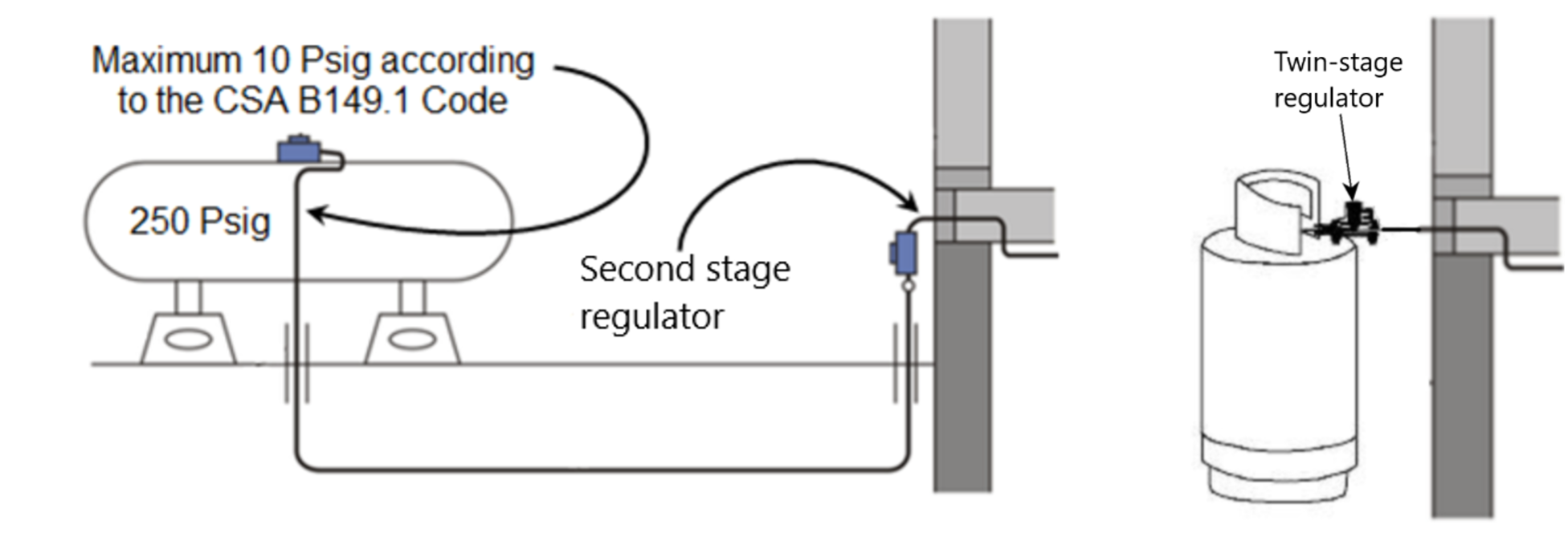
For propane systems, service regulators are installed by the gas technician/fitter between the storage container and the building. Propane service regulators are also called second stage regulators or twin stage regulators (Figure 15).
The maximum delivery pressures within various types of buildings are listed in section 5.1 of the CSA B149.1 gas code. For example the maximum allowed pressure in a single-family dwelling is 2 psig.
Appliance regulators
Appliance regulators are located on the valve train of the appliance to reduce the inlet pressure of the appliance to the appropriate manifold pressure required for proper burner performance (Figure 16). The main purpose of the appliance regulator is to maintain a relatively constant gas outlet pressure to the burner(s) to assure constant, even flame at the main burners.
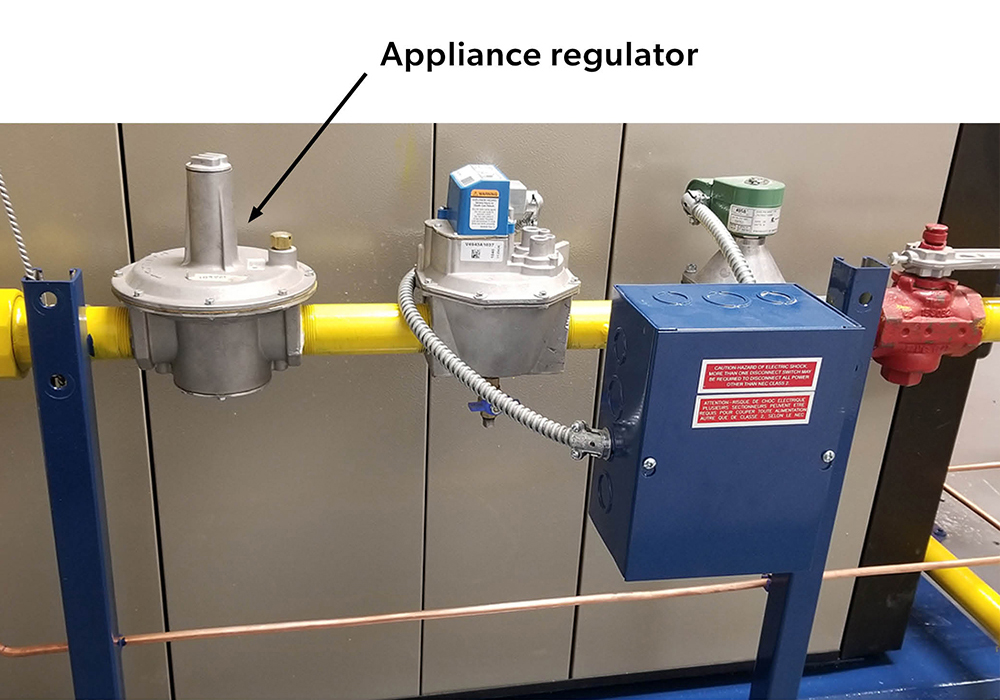
Most natural gas appliances require a manifold pressure of 3” to 4” WC, while propane appliances typically require 10” to 11” WC. Residential and commercial appliances will typically have an appliance regulator with a maximum inlet pressure of 0.5 psig (14” WC).
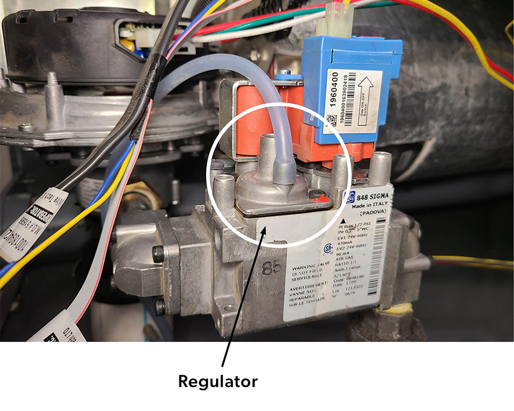
For appliances with inputs less than 400 MBH the appliance regulator is often included as part of a combination gas valve (Figure 17). These combination valves often employ servo operated regulators that can have the manifold pressures stepped or modulated down to as low as 0.5” WC. Combination gas valves will be looked at in greater detail in B1 LT4.
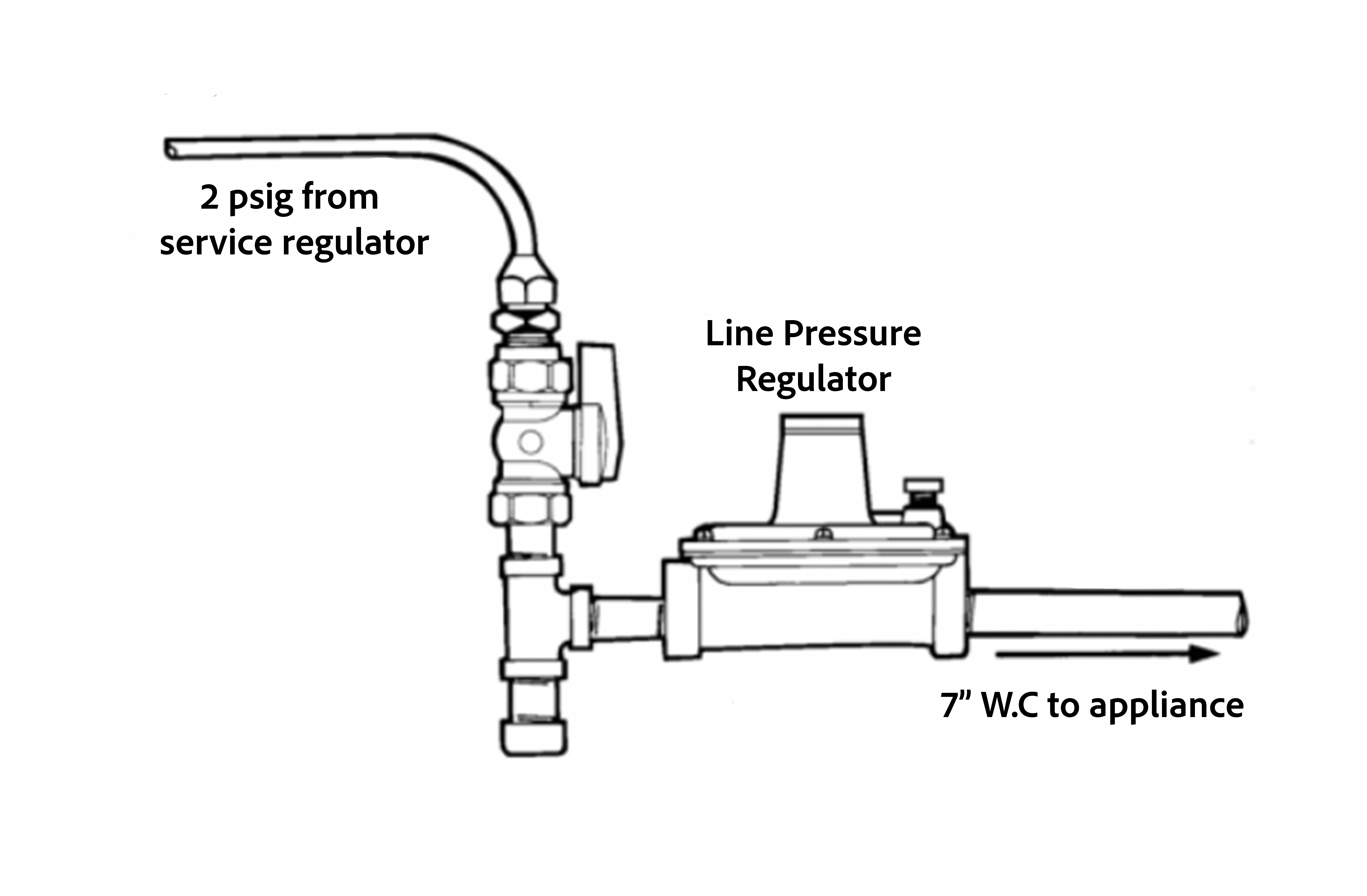
Line pressure regulators
The service regulator will often deliver a building line pressure that exceeds the maximum allowable pressure specified for the gas appliance. In these cases, line pressure regulators are installed between the building’s service regulator, or LP-gas 2 psig (13.8 kPa) service regulator, and the gas appliance. For example, a 2 psig service will need to be reduce to a maximum of 0.5 psig (14” WC) as that is the maximum inlet pressure to most appliance regulators (Figure 18).
Line pressure regulators are classified in accordance with their intended application and are designated either Class I or Class II.
- Class I regulators have a maximum outlet pressure setting of ½ psig as they are used primarily with residential and light commercial appliances that have ½ psig maximum rated inlet pressures. They can be certified for a rated inlet pressure of 2, 5, or 10 psig.
- Class II regulators have a maximum outlet pressure setting of 2 psig as they are used primarily with industrial appliances that have 2 psig maximum rated inlet pressures. They can be certified for a rated inlet pressure of 5 or 10 psig.
Line pressure regulators used for installations with a supply pressure exceeding 2 psig require a tested and approved overpressure protection device (OPD), to prevent the outlet pressure from exceeding the rated pressure of the system components.
High pressure regulators
A high pressure regulator is similar to a line pressure regulator except it is used for applications where the inlet gas pressure is greater than 10 psig (70 kPA) and an outlet pressure is greater than 2 psig (14 kPA). An example could be if the gas service was routed directly into the mechanical room of a hotel at the maximum allowable pressure of 20 psig to serve the boiler loads, and then continued from the mechanical room into the hotel to serve other loads. This would require an additional regulator to reduce the gas pressure to a maximum of 5 psig before it left the mechanical room. The other equipment throughout the hotel would still require one of more line pressure regulators to reduce the pressure to ½ psig for the appliances.
Operating types
All regulators maintain a pre-determined outlet pressure to control the quantity of gas flow. They are pressure operated, and no other power source is required for their operation. All regulators are one of these two operating types:
- Direct-operated
- Pilot operated
Direct-operated regulators
Direct-operated regulators, also known as self-operated regulators, are the simplest type of pressure regulator and are the most common. Direct-operated regulators are a self-contained valve and actuator combination (Figure 19). They use the actual downstream pressure directly in the actuator to position the valve accordingly and match the gas demand.
In operation, a direct-operated, pressure regulator senses the downstream pressure through either internal port or an external control line. This downstream pressure opposes a spring which moves the diaphragm and valve plug to change the size of the flow path through the regulator.
Pilot-operated regulators
Pilot-operated regulators are used for high flow rates or where precise pressure control is required. A pilot-operated regulator can be simplified by viewing it as two independent regulators connected together (Figure 20). The smaller of the two is generally the pilot. The pilot is a pressure amplifier as it senses to downstream pressure to then create the necessary loading pressure to the main regulator diaphragm. This improves the overall sensitivity and accuracy of the regulator.
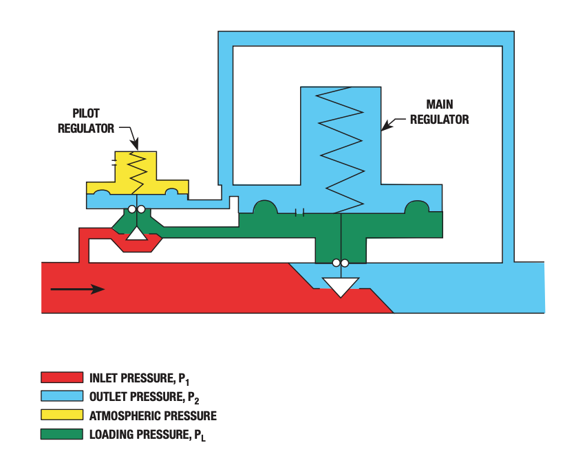
As these regulators are primarily used on larger commercial, institutional and industrial applications they are covered in greater detail in the Class “A” training.
Regulator Operation
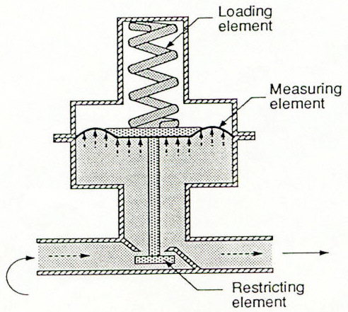
Although direct -operated regulators are available in many different styles and designs their basic operating principles and the same. All regulators have three basic operating elements or components that are used to control flow rates as well as pressure shown in Figure 21.
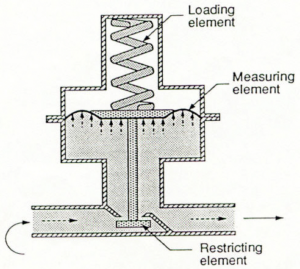
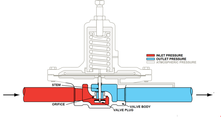
Restricting element
The restricting element consists of the valve body, orifice, valve plug, and stem (Figure 22). Together they control the amount of flow through the orifice opening. As the stem is moved upward, the valve plug moves toward the orifice, restricting flow. Flow through the orifice is increased by moving the stem downward, away from the orifice.
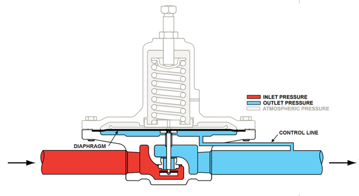
Measuring element
The measuring element provides feedback to the regulator on whether the flow demand is being matched. The measuring element is usually a diaphragm that senses the changes in the downstream pressure (Figure 23). Made of neoprene, it is extremely flexible and usually is supported by a metal plate that allows downstream pressure to act upon the diaphragm evenly. The plate is connected to the valve stem so it will modulate the valve plug position based on the downstream pressure it senses through the control line or internal port.
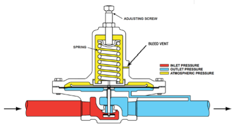
Loading element
On modern regulator the loading element is a spring used to counter balance the force created by the downstream pressure on the underside of the diaphragm (Figure 24). The springs opening force is changed with the adjusting screw. This will adjust the desired outlet pressure, known as the regulators setpoint.
Principles of operation
The help understand the operation and troubleshooting of regulators it is worth noting that an uninstalled direct operated regulator is in the normally open (NO) position, as the closing force requires downstream gas pressure.
We will begin the operating sequence as if it is a newly installed gas piping system that is just being pressurized.
- As the systems fills gas will flow through the open valve, the gas pressure downstream of the regulator will begin to increase, filling the chamber below the diaphragm causing it to move upward against the spring tension. Air exiting the upper chamber through the bleed vent allows the diaphragm to move freely. The upward movement of the diaphragm closes the valve. The amount of downstream pressure necessary to close the valve is directly related to the force exerted by the spring on top of the diaphragm. This is called the set point.
- When an appliance starts, gas pressure under the diaphragm decreases allowing the spring to push the diaphragm downward opening the valve. Air entering the bleed vent allows the diaphragm to move freely.
- The diaphragm and valve stabilize when the force under the diaphragm equals the force exerted by the spring. At this point the regulator has found its point of equilibrium and the flow rate and pressure downstream match that which is required by the system.
- If additional appliances start or an increase in firing rate occurs, the diaphragm moves further downward and the valve stabilizes in a new position in relation to the orifice, allowing more gas flow at the same pressure setpoint.
- If gas demand decreases or stops, the diaphragm moves upward and the valve stabilizes in a new position in relation to the orifice, allowing less gas flow at the same pressure. Air entering and exiting the vent allows the diaphragm to move freely.
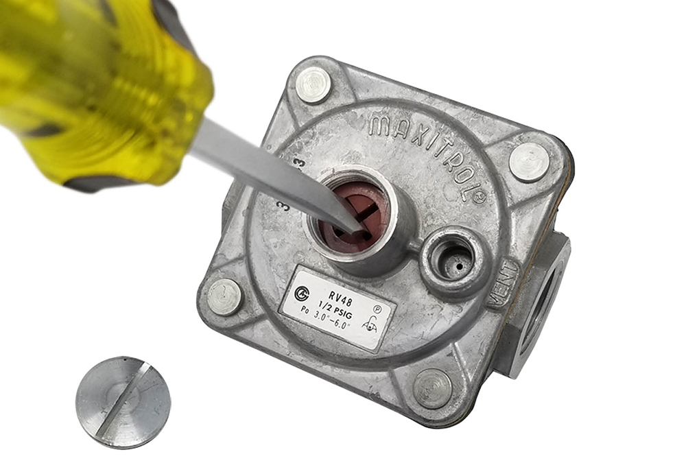
Adjusting setpoint
Regulators can be adjusted to change the outlet pressure setpoint within certain limits of the spring range. The desired outlet pressure can be changed by adjusting the screw in its housing (Figure 25) to increase or decrease the force exerted by the spring on the flexible diaphragm.
Use the following procedure to change the setpoint:
- Turn off the gas.
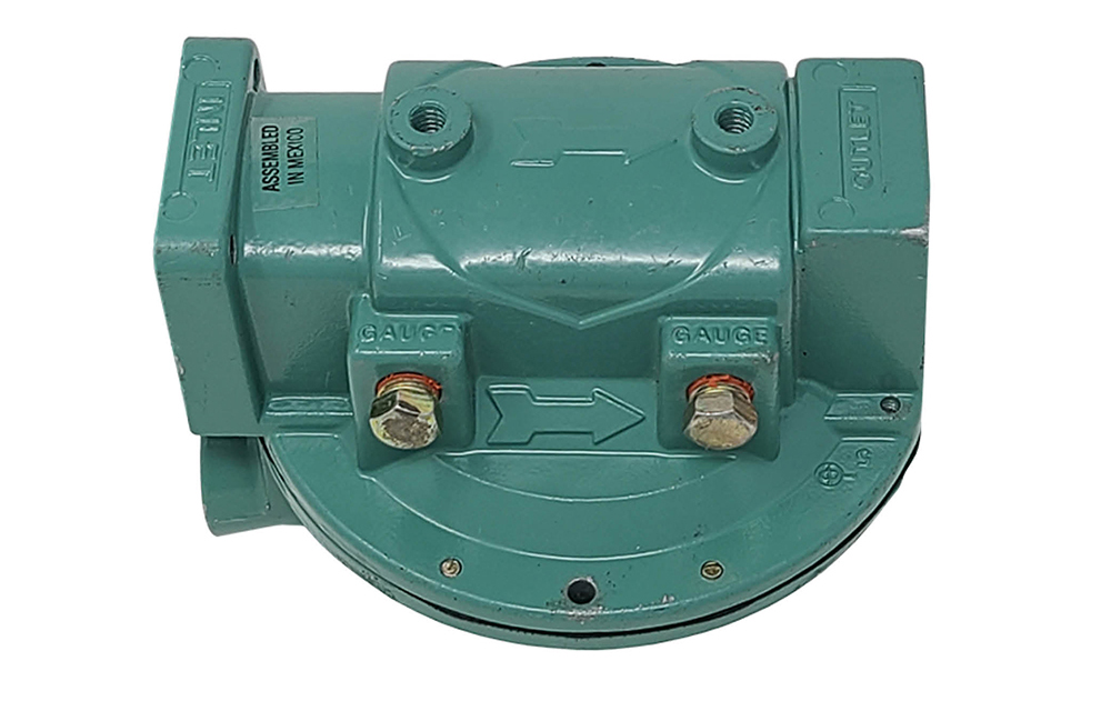
- Install the pressure test equipment to sense downstream pressure. Some regulators will have threaded pressure plugs on the valve body to connect (Figure 26). But many will not have gauge connections and you will need to find an appropriate connection point.
- Remove the regulator adjusting screw cap.
- Turn on the gas.
- Turn the equipment on, allowing the gas to flow.
- Look at the pressure and make the appropriate adjustment. To increase the outlet pressure, turn the adjusting screw clockwise to increase the tension is applied to the spring. For a lower outlet pressure, the adjusting screw is turned counter-clockwise to lessen the tension on the spring.
- Replace the cap.
- Shut off the gas.
- Remove the test equipment.
- Properly plug any test points.
- Turn on the gas
- Leak test the test points.
- Check the operation of the appliances or burners downstream of the regulator to ensure that they are in safe operating condition.
Performance Characteristics
The importance of a regulators performance characteristic is frequently misunderstood. Ideally a regulator would provide a range of flow rates with-out a drop in downstream pressure, this however is unrealistic. The only way the internal parts of a regulator will move in any direction is if the diaphragm senses a change in that outlet pressure. In order for the flow rate to increase through a regulator, the restricting element must open wider, which can only be done by a drop in pressure. If the regulator hasn’t opened enough to satisfy demand, the downstream pressure will have to decrease further for the regulator to open more. The term used for this characteristic is droop or offset.
Droop
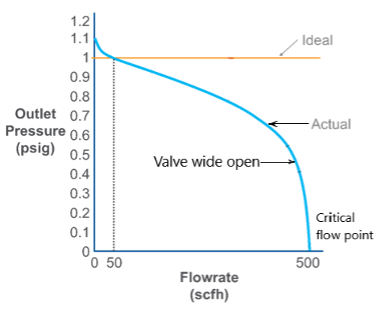
When the flowrate versus outlet pressure of a particular regulator is plotted the actual performance curve looks like the Figure 27. For this regulator the ideal setpoint is made at a flow of 50 SCFH, but that is the only flowrate at which outlet pressure will precisely equal setpoint. Any time the flow demand is greater than 50 SCFH, outlet pressure will droop below 1 psig.
Notice at the maximum flowrate of 500 SCFH through the regulator the outlet setpoint would be 0 psig, this would obviously not be an acceptable amount of pressure to operate any of the gas equipment.
A regulator can pass only so much flow for a given valve seat orifice size and inlet pressure. Notice how quickly the regulators performance drops off after the regulator valve has reached the wide-open position (when the disk clears the orifice by a distance equal to ¼ of the orifice diameter). At the point of critical flow the gas has reach its maximum velocity through the orifice. This velocity is known as the sonic velocity which is the speed of sound for that particular gas. At this point the only way to increase the flow through the valve would be to increase the upstream pressure.
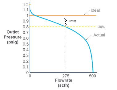
In order to ensure the outlet pressure is much closer to setpoint manufactures will publish the droop as a percentage of the setpoint pressure. For propane and natural gas, droop accuracy ratings of 10% to 20% are typical.
In Figure 28 for a 20% accuracy, 275 SCFH flow would be published because that is the maximum flowrate before the regulator’s performance droops outside the 20% accuracy bounds. If the flow demand is less than 275 SCFH, the outlet pressure will be closer to setpoint. Likewise, if flow demand exceeds the published 275 SCFH, it would be less accurate and possible not deliver adequate pressure to operate the equipment and burner properly.
Lockup
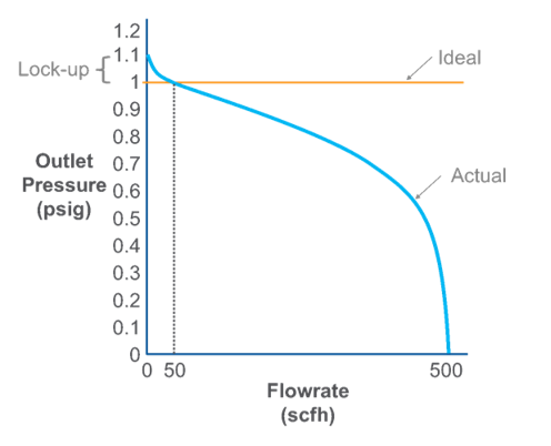
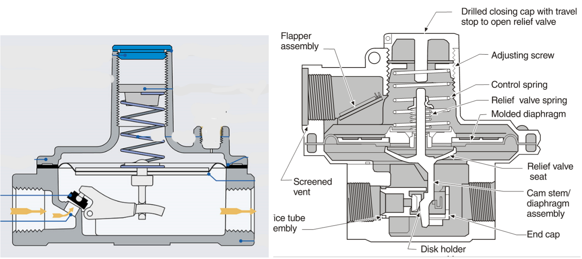
The amount of increased pressure above setpoint needed to achieve shutoff is called lock-up (Figure 29). Lock-up is an important regulator characteristic because it affects how well the pressure regulator fulfills its reason for existence: maintaining a constant outlet pressure. Typically, regulators that have inlet pressures above 0.5 psig must be of the positive shut-off type, which means the valve disk has a soft seated disc and the valve seat or orifice has a tapered machined edge. These regulators will usually lock up to within 10% of the original outlet pressure setting.
Lever and cam stem operators
Service, high and line pressure regulators typically have to operate with a greater the difference in pressure between the inlet and outlet of a regulator. These conditions will require a larger diaphragm to maintain accuracy and lockup. The similar result is obtained by using a lever or a cam stem to multiply the force produced by the diaphragm. Lever and cam stem controlled (Figure 30) regulators provide increased force necessary for lockup against higher inlet pressures. The extra mechanical force also keeps the disk in a stable position, thereby opposing tendencies of the disk to cycle or buffet.
Boost
In the previous operating explanations regulator were used with an external control lines sensing a point downstream of the regulator. The performance curves showed that as flow increased, the regulator failed to maintain setpoint due to droop and the performance eventually fell below an acceptable pressure. The more typical regulator has an internal sensing port or tube. Internally sensing direct-operated regulators not only experience droop; they also have a counteracting force called boost that can cause the performance to exceed accuracy requirements on the high end. Boost can be used to counteract the effects of droop by extending the flowrate at which the regulator maintains accurate pressure control.
The internal sensing regulator senses the pressure inside the valve body which is a turbulent location with high velocity. At a point near the orifice outlet, called the vena contracta, the velocity is highest the pressure will be lowest. As flow demand increases, so does velocity at the sensed point, causing an increasing discrepancy between the pressure at the regulator’s sense location (at the vena contracta) and the downstream pressure (Figure 31).
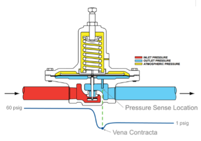
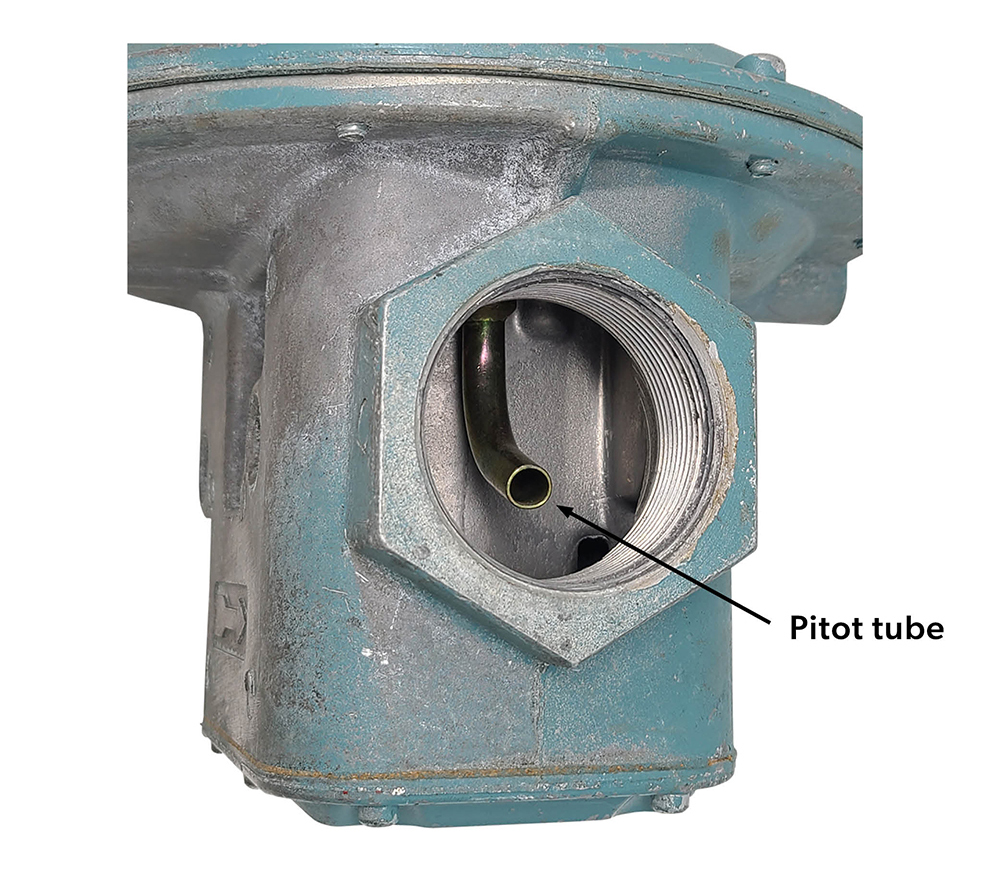
Consequently, the internally-sensing regulator is tricked into opening farther due to this false low pressure, then if it had been sensing pressure through an external downstream control line. This increased flow can translate into improved accuracy. Some internal sensing regulators have a pitot tube in order to place the sensing point at the optimal location (Figure 32), so that the boosting effect will counteract the droop effect but not boost too much.
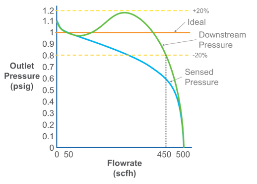
Boost can be beneficial for extending how much of the regulator’s performance curve falls within the published accuracy. Figure 33 is an example of an internally registered unit that boosts so much that it almost exceeds the upper accuracy bound. For 20% accuracy, the maximum flowrate published would be 450 SCFH which is much better than the 275 SCFH that would be published for the same regulator previously discussed with an external control line.
Balanced diaphragm
Another method that regulator manufactures use to overcome the effects of the inlet pressure on the valve seat is to add a balancing diaphragm (Figure 34). The inlet pressure exerted downwards on the inner valve disk also pushes upwards on the balancing diaphragm. The effective areas are equal, so the forces push equally in both directions. The balancing diaphragm is attached and sealed to the valve shaft and separates the lower main diaphragm area and the upper valve section. This design makes it possible to maintain steady outlet pressure control with widely varying inlet pressures, and minimum lockup with either high or low inlet pressures.
Regulator Vent
The regulator vent (atmospheric vent, bleed vent) is an essential part of the regulator, so much that it is sometimes referred to as the fourth operating element of the regulator. It allows the air above the diaphragm to escape or enter as the diaphragm moves up or down. If the vent is blocked or restricted, the diaphragm is not able to move properly. For example, if the vent was completely blocked it would cause the air above the diaphragm to become locked in and prevent the diaphragm from raising enough to close the restricting element. This will create a situation in which the downstream pressure will rise above the required setpoint.
If the vent were partially blocked or restricted, the air movement would be delayed as the diaphragm attempts to force air out and pull air through the vent opening. This would in turn cause wide swings in downstream pressure above and below the setpoint known as “hunting” or “cycling”.
The vent also allows gas to escape if the diaphragm ruptures or an internal relief valve opens. There are special installation safety measures that are required to control this potential escaping gas that will be discussed in Section B-2.
Propane Systems
Propane system are different than natural gas systems in that the propane supply pressure from the storage tank will vary due to changing air temperature. Propane storage container pressures could vary from as low as 8 psig (55 kPa) in winter to as high as 220 psig (1500 kPa) in summer. For any regulator the greater the difference in pressure between the inlet and outlet of a regulator, the more difficult it is for the regulator to maintain accuracy This is why propane systems typically use two regulators between the propane tank and the appliance. For example, the CSA B149.1 code states; that two stage reduction is required for all permanent installations and that the pressure between the first stage and second stage regulator shall not exceed 10 psig. However, this maximum allowed pressure difference should be reduced to 5 psi in colder climates, to prevent the vapor from changing into liquid.
By doing a two stage reduction the first stage of the system supplies a nearly constant inlet pressure of 8 to 10 psig (55 to 70 kPa) to a second-stage regulator. This means that the second-stage regulator does not have to compensate for as much variance in inlet pressures, as the first stage regulator will supply it with a relatively constant inlet pressure.
There are two methods that are used for two stage regulation which were shown previously in Figure 13.
- Two separate regulators – one on the tank and one at the building entrance, or
- One twin stage regulator that performs both functions internally. Used only when piping distances are 30 ft (9 m) or less from the tank to the building.
Mechanical burners
Mechanical burners use a fan, blower, or compressed air to supply the required amount of combustion air and may also assist in venting the products of combustion.
In the past mechanical burners were primarily found only in industrial and large commercial combustion systems. With the modulating condensing technology used on most modern-day small commercial and residential appliances, mechanical burners are very common. These often come in the form of a pre-mix burner that will mix the gas and air upstream of the burner port.
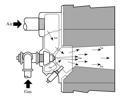
Nozzle mix burners mix the gas and air together as they enter the burner nozzle. Both the air and gas are injected into the burner at a positive pressure (Figure 35). On a variable input appliance (modulating) the air pressure or flow can be modulated but the gas pressure or flow must also be automatically adjusted to remain in direct proportion to the air.
The aspirator (venturi) type of pre-mix burner (Figure 36) uses high velocity air travelling through a venturi to entrain and mix with the required gas supply.
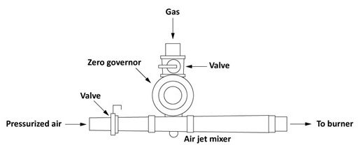
To maintain proportion gas/air mixtures, venturi modulating burner systems require a pressure regulator that can automatically change its gas flowrate to match a change in the combustion air supply. These regulators are called zero governor/ratio regulators.
Zero governor/ratio regulators
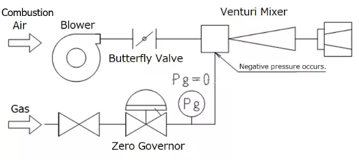
Zero governor regulators control the outlet pressure with a goal of zero pressure, relative to atmosphere, at the outlet. They will allow the flow of gas to only occur when a negative pressure is sensed at the valve outlet. They sense the reduced pressure at the venturi when the combustion air is flowing, and open in proportion to the speed of the air flow.
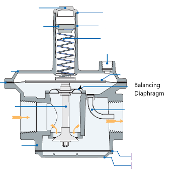
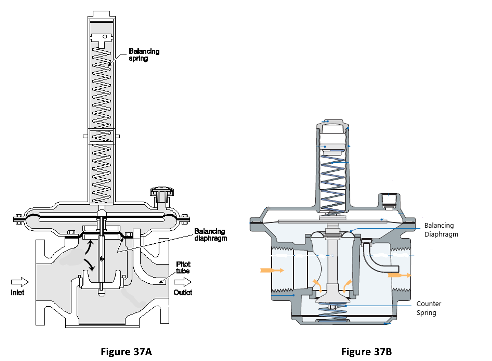
They are balanced diaphragm designs with a very light balancing spring designed to only lift the force created by the weight of the moving parts (Figure 37A).
For another very common design shown in Figure 37B, the manufactures have simply added a counterbalancing spring to the under side of the valve disc of their balanced diagram regulator. The counterspring acts against the downward forces created by the setpoint spring and the weight of the moving parts. It should be noted these rely on gravity so should no be mounted upside down.
These regulators are ideal for gas engines and modulating aspirator burners as they will automatically change the gas flow to match any changes in the air flow through the venturi mixer (Figure 38).
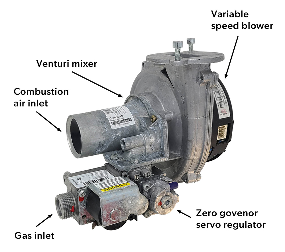
Commercial and residential modulating/condensing boilers and on-demand water heaters, will have all of the components in one packaged burner assembly (Figure 39). A zero governor servo regulator is incorporated into the combination gas valve. Instead of a butterfly valve to adjust the combustion air flow a variable speed motor is used on the blower to change the air flow. As the blower modulates to meet the heat demand the zero governor changes the gas input to automatically achieve proportional mixing.
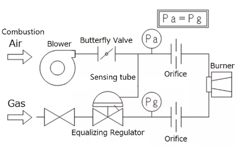
For nozzle mix burners a ratio (equalizing) regulator supplies gas to a burner at a pressure that is in direct (1:1) proportion to the air pressure supplied to the burner (Figure 40). As the air pressure to the burner increases, then the ratio regulator causes the gas pressure at the gas limiting orifice to increase. Conversely, if the air pressure decreases, then the gas pressure decreases. A ratio regulator is a zero governor regulator with a sensing tube connected to the regulator bleed vent. This line loads the air pressure into the diaphragm chamber, causing the loading element force to increase. The result is a gas pressure setpoint that will match the combustion air pressure. When there is no air pressure this zero governor type regulator will return to the closed position.
 Now complete Self-Test 3 and check your answers.
Self-Test 3
Self-Test 3
Media Attributions
- Figure 14. “Natural gas meter set” by Rod Lidstone is licensed under a CC BY-NC-SA licence.
-
Figure 15. “Propane service regulators” – The source for this image is unknown. It is being used for non-commercial, educational purposes. To receive credit for this image, please reach out to the publisher.
- Figure 16. “Appliance regulator in valve train” by Rod Lidstone is licensed under a CC BY-NC-SA licence.
- Figure 17. “Appliance regulator as part of a combination gas valve” by Rod Lidstone is licensed under a CC BY-NC-SA licence.
- Figure 18. “Line Pressure Regulator” from Ordan Thermal Products LTD is used and adapted for educational purposes under the basis of fair dealing.
- Figure 19. “Direct operated regulator” from Diploma In Gas Engineering Technology is used for educational purposes under the basis of fair dealing.
- Figure 20. “Pilot-operated regulator” from Emerson is used for educational purposes under the basis of fair dealing.
- Figure 21. “Operating elements” from Diploma In Gas Engineering Technology is used for educational purposes under the basis of fair dealing.
- Figure 22. “Restricting element” from Emerson is used and adapted for educational purposes under the basis of fair dealing.
- Figure 23. “Measuring element” from Emerson is used and adapted for educational purposes under the basis of fair dealing.
- Figure 24. “Loading element” from Emerson is used and adapted for educational purposes under the basis of fair dealing.
- Figure 25. “Turning adjusting screw” by Rod Lidstone is licensed under a CC BY-NC-SA licence.
- Figure 26. “Regulators with pressure test ports” by Rod Lidstone is licensed under a CC BY-NC-SA licence.
- Figure 27. “Regulator performance curve” from Emerson is used and adapted for educational purposes under the basis of fair dealing.
- Figure 28. “Droop accuracy bounds” from Emerson is used and adapted for educational purposes under the basis of fair dealing.
- Figure 29. “Lockup performance” from Emerson is used and adapted for educational purposes under the basis of fair dealing.
- Figure 30. “Lever and cam step regulators”.
- “325-L series Line Pressure Regulators” (Left) from Maxitrol is used and adapted for educational purposes under the basis of fair dealing.
- “Cam step regulator” (Right) – The source for this image is unknown. It is being used for non-commercial, educational purposes. To receive credit for this image, please reach out to the publisher.
- Figure 31. “Vena contracta” from Emerson is used and adapted for educational purposes under the basis of fair dealing.
- Figure 32. “Pitot tube” by Rod Lidstone is licensed under a CC BY-NC-SA licence.
- Figure 33. “Regulator boost performance curve” from Emerson is used and adapted for educational purposes under the basis of fair dealing.
- Figure 34. “Balanced diaphragm regulator” from Maxitrol is used and adapted for educational purposes under the basis of fair dealing.
- Figure 35. “Nozzle mix burner” – The source for this image is unknown. It is being used for non-commercial, educational purposes. To receive credit for this image, please reach out to the publisher.
- Figure 36. “Aspirator (venturi) mixer” by Camosun College is licensed under a CC BY 4.0 licence.
- Figure 37. “Zero governor regulators”.
- Figure 37A (Left) – The source for this image is unknown. It is being used for non-commercial, educational purposes. To receive credit for this image, please reach out to the publisher.
- Figure 37B (Right). “R Series” from Maxitrol is used and adapted for educational purposes under the basis of fair dealing.
- Figure 38.”Venturi mixer schematic” from ITO Corporation is used for educational purposes under the basis of fair dealing.
- Figure 39. “Venturi Mixer Burner Assembly” by Rod Lidstone is licensed under a CC BY-NC-SA licence.
- Figure 40.”Nozzle mixer schematic” from ITO Corporation is used for educational purposes under the basis of fair dealing.
