Learning Task 1
Describe Gas Burners
Burners are designed in different shapes and sizes to accommodate the wide variety of heat exchangers and combustion chamber requirements. It is important for you to know the special characteristics of the different burners you are likely to encounter in the gas industry.
Burner Terminology
The world of burners has its own language and terms. An introduction to some of these terms and their definitions will help you when they get used in context.
High fire
High fire is the design maximum firing rate of a burner. It represents the maximum fuel input and heat output a burner can safely be operated at in a particular application.
Low fire
Low fire is the minimum input of fuel that is required to keep a burner from flaming out. This is similar to an automobile: If gasoline intake were reduced while a vehicle was idling, the engine would stall.
Modulation
Burner modulation is used to vary the gas input to vary the heat output to a process in order to match the heat load requirement and sustain the desired temperature. Modulating controls can regulate a burner between high and low fire in a continuously variable manner,
Turndown ratio
The turndown ratio is defined as the ratio of the maximum fuel input rate to the minimum fuel input rate for a modulating burner. It is used to help determine how low a boiler can modulate before it turns off. For example, the turndown ratio for a gas fired burners may be listed as 5:1. This means the burner can modulate as low as 20% off its full rated input.
Port loading
The term port loading refers to the amount of gas-air mixture passing through a burner that will create a stable flame. Burner port loading is expressed as the number of Btus per square inch of port area. The port loading can be changed by altering either the orifice size or the gas pressure (manifold pressure). For most applications using natural gas, a port loading between 25,000 Btus and 30,000 Btus per square inch of port area provides a stable flame.
Burner Types
Gas burners can be either mechanical or non-mechanical depending on how the combustion air is being supplied. Classifying burners can be very confusing because there are no standard definitions the following represent some of the more common industry accepted terms.
Non-Mechanical Burners
Non-mechanical or “atmospheric burners” rely on atmospheric pressure to supply the required combustion air. An atmospheric burner has a venturi that sucks primary air into the burner and mixes the air and gas before ignition (Figure 1).
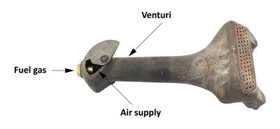
The operation and parts of atmospheric burners will be discussed in much greater detail in E-5 Learning Task 2, Describe Atmospheric Burners.
Mechanical Burners
Mechanical burners use a fan or blower to supply the required amount of combustion air and may also assist in venting the products of combustion.
Mechanical burners are categorized based on either; the location of the fan or blower in relation to the combustion chamber, or the air pressure being delivered through the burner and where the gas and air are mixed in the burner.
Here are some of some of the types of mechanical burners.
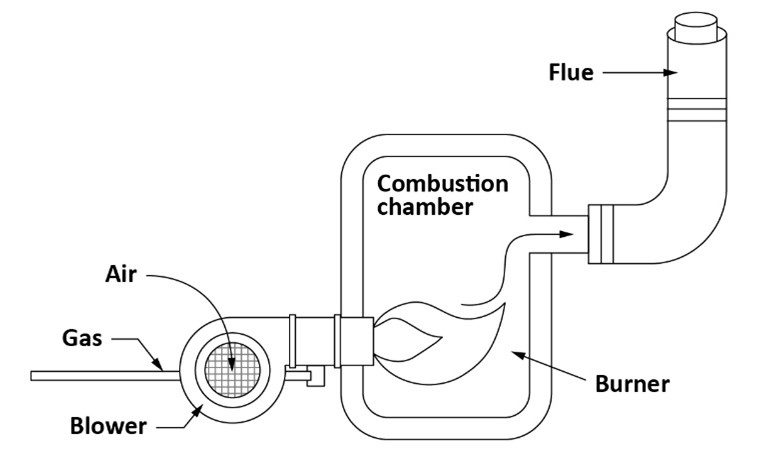
Forced draft burner
In a forced-draft burner, combustion air is supplied by a fan or blower at sufficient pressure to overcome the resistance of the burner and the appliance. Therefore, the blower in a forced draft burner supplies the air to the burner and also forces the products of combustion through the appliance. The fan or blower is located upstream of the combustion zone as shown in Figure 2.
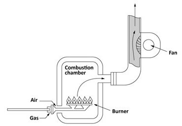
Induced draft burner
The induced-draft burner uses the mechanical draft produced by a fan located on the downstream, or chimney side, of the combustion zone as shown in Figure 3. The fan is designed to pull in the required air supply for combustion and vent the products of combustion with a positive vent pressure.
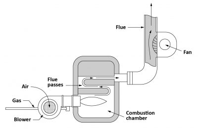
Balanced draft burner
The balanced-draft burner system has a combination of forced and induced draft, were one fan is located upstream, another is located downstream of the combustion chamber (Figure 4). The combustion air is forced through the burner and then pulled from the combustion chamber by an induced draft fan. This is more common with larger boilers with multiple passes where the flue gases have to travel a long distance.
Fan-assisted burner
A fan-assisted burner is a burner in which the combustion air is supplied by a mechanical device such as a fan or blower at sufficient pressure to overcome the resistance of the burner only.
The fan can be located upstream as is the case with a fan-assisted conversion burner (Figure 5 left), or downstream as in the fan-assisted combustion system shown on the right of Figure 5.

These systems are often described as forced or induced fan assisted systems, which can make them easy to confuse with the previously described forced and induced draft powered burners. For fan-assisted systems the fan only gives a more precise control over the air entering the combustion chamber, compared to that of a natural draft burner. The combustion products are vented naturally with a nonpositive vent stack pressure.
Pre-mix burners
Industrial combustion systems that require a short, hot flame with a high-heat release may use a burner that pre-mixes the gas and air upstream of the burner. There are three types of pre-mix burners:
- Inspirator or Gas Jet Mixer;
- Aspirating Mixer, and
- Mechanical Mixer
Pre-mix burners mix the required amounts of air and gas before ignition.
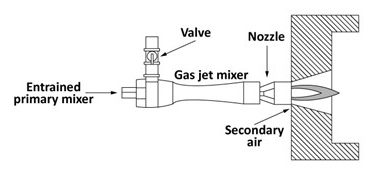
Inspirator mixer
An inspirating burner system uses high pressure gas, of 10 psi or more. When the gas is issued at high velocity through an orifice within a gas-jet mixer it entrains and mixes the required combustion air from the ambient air (Figure 6). Inspirators can entrain and pre-mix up to 100% of the required combustion air.
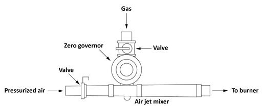
Aspirating mixer
An aspirating burner system uses pressurized air, issued at high velocity through a venturi to entrain and mix the gas. Gas is drawn from an atmospheric regulator (or zero governor) in proportion to the amount of air flowing into the burner (Figure 7). This allows the air-to-gas ratio to stay the same and provides a consistent flame throughout the firing range of the burner. In recent years these burners have become common on residential and commercial condensing boilers due to there excellent turndown ratio.
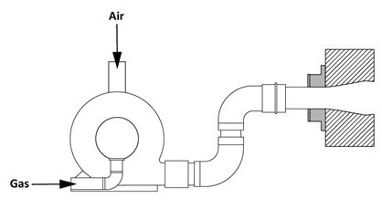
Mechanical mixers
A mechanical mixer is a fairly straight forward idea, a fan or blower are used to mix and supply both the air and the gas to a burner (Figure 8). Because ratio control is accurate and independent of the volume delivered, a number of burners may be supplied independently. Although there has to be design measures incorporated to prevent the fuel air mixture from burning back through the burner head into the mixture piping (flashback).
Flame Stability
All burners have unique performance envelopes, or the range of flows and gas/air ratios, over which they are stable and operate reliably. Burners create a stable flame by balancing the different combustion properties of the gas-air mixture. Exceeding any of the combustion limits of the fuel gas and the combustion process will not generate enough heat to keep the chain reaction going, and the burner will go out.
Combustion Properties
The combustion properties that have the greatest effect on burner flame stability are:
- Limits of flammability
- Maximum flame speed
- Ignition temperature
- Maximum flame temperature
Limits of flammability
The limits of flammability are the upper and lower ranges of gas in the air-gas mixture that will support combustion. For example, the perfect ratio for natural gas is 10 parts air to one-part gas. It is possible to get a mixture to burn within a ratio of 4 to 15% natural gas to air.
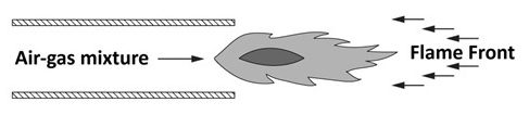
Maximum flame speed
Flame speed is the velocity at which the flame front moves or propagates towards the air-gas mixture issuing from the burner. Although natural gas will burn at a ratio of approximately 4-15% fuel, the flame speed varies by the air-gas mixture and the type of gas. For example the maximum flame speed of 12″ per second for natural gas is only achievable at the perfect 10% mixture.
Stable flames have a balanced air-gas flow velocity and flame speed keeping the flame front close to the burner port (Figure 9). If any condition changes the balance between the flow velocity and the flame speed, unstable flames are created.
Ignition temperature
Ignition temperature is the temperature at which an air-gas mixture will initiate and support combustion. It varies according to the fuel gas used.
Flame Temperature
Each fuel gas has its own maximum flame temperature. Maximum flame temperature can only be reached at perfect combustion which is the ideal theoretical combustion ratio.
The flowing table summarizes the combustion properties for the three common fuel gases.
| Combustion Property | Natural Gas | Propane | Butane |
|---|---|---|---|
| Limits of flammability | 4 ~ 15% | 2.4 ~ 9.5% | 1.9 ~ 8.5% |
| Maximum flame speed | 12″/sec | 18″/sec | 18″/sec |
| Approximate ignition temperature | 700°C (1,300°F) | 490°C (920°F) | 480°C (900°F) |
| Approximate maximum flame temperature | 1,980°C (3,600°F) | 1,980°C (3,600°F) | 1,980°C (3,600°F) |
A full list of fuel gas properties can be found in Annex I of the CSA B149.1 Natural gas and propane installation code.
Stabilizing Methods
As was previously mentioned, stable flames have a balanced air-gas flow velocity and flame speed, therefore the flow rate of the gas/air mixture through the burner has an effect on its operating range.
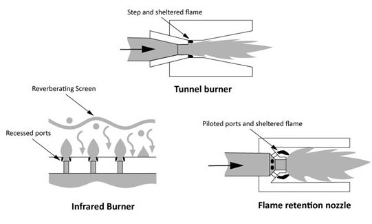
To maximize heat output burner ports may need to operate with flow velocities which can create unstable flames. The high operating range of the burner can be improved by designing it to incorporate areas where the mixture velocity is lower. Part of the gas/air mixture flows into these sheltered areas and burns, generating enough heat to ignite the gas/air mixture leaving the burner head. These are called flame retention devices. Burner designers will add some sort of flame stabilizing device, spin vanes, a disc or tabs at the point where the gas and air come together (Figure 10), to assist the mixing process and also provide the flame with a sheltered spot to anchor itself.
 Now complete E-5 LT1 Self-Test and check your answers.
Self-Test 1
Self-Test 1
- What term refers to the minimum input of fuel that is required to keep a burner from flaming out?
- Low-fire
- Modulation
- Port loading
- Turndown ratio
- What term is used to help determine how low a boiler can modulate from maximum firing rate before it turns off?
- High fire
- Low-fire
- Port loading
- Turndown ratio
- What type of burner relies upon atmospherics pressure to supply all of its combustion air?
- Non-mechanical burner
- Forced draft burner
- Induced draft burner
- Balanced draft burner
- What type of burner uses a fan located downstream of the combustion zone to pull in the air supply for combustion and vent the products of combustion with a positive vent pressure.
- Forced draft burner
- Fan -assisted burner
- Induced draft burner
- Balanced draft burner
- What type of burner uses a mechanical device to supply combustion air at the pressure necessary to only overcome the resistance of the burner.
- Forced draft burner
- Fan -assisted burner
- Induced draft burner
- Balanced draft burner
- What type of mechanical burner relies on the products of combustion to be vented naturally with a nonpositive vent stack pressure.
- Forced draft burner
- Fan -assisted burner
- Induced draft burner
- Balanced draft burner
- Which type of pre-mix burner has become very common in residential condensing boilers?
- Gas jet mixer
- Aspirating mixer
- Inspirator mixer
- Mechanical mixer
- What are the limits of flammability for natural gas?
- 10%
- 2.4%–9.5%
- 4%-15%
- 1.9%-8.5%
- What is the approximate maximum flame temperature for Propane, Butane and Natural gas?
- 480°C
- 490°C
- 700°C
- 1980°C
- What is the purpose of burner flame retention devises?
- Increase flame lifting
- Reduce gas mixture velocity
- Retain heat at the burner port
- Stabilize flame by reducing the ignition temperature
Check your answers using the Self-Test Answer Keys in Appendix 1.
Media Attributions
- Figure 1 “Atmospheric burner” by Camosun College is licensed under a CC BY 4.0 licence.
- Figure 2 “Forced draft burner” by Camosun College is licensed under a CC BY 4.0 licence.
- Figure 3 “Induced draft burner” by Camosun College is licensed under a CC BY 4.0 licence.
- Figure 4 “Balanced draft system” by Camosun College is licensed under a CC BY 4.0 licence.
- Figure 5 “Fan-assisted systems” by Camosun College is licensed under a CC BY 4.0 licence.
- Figure 6 “Industrial inspirator burner” by Camosun College is licensed under a CC BY 4.0 licence.
- Figure 7 “Aspirating mixer” by Camosun College is licensed under a CC BY 4.0 licence.
- Figure 8 “Mechanical mixer” by Camosun College is licensed under a CC BY 4.0 licence.
- Figure 9 “Flame propagation” by Camosun College is licensed under a CC BY 4.0 licence.
- Figure 10 “Flame retention methods” by Camosun College is licensed under a CC BY 4.0 licence.
