Learning Task 2
Describe Factors that Affect Fluid Flow in a Piping System
In physics the flow of fluids (liquids and gases) is described as fluid dynamics. The affect on the gas pressure energy is one of the most important aspects to consider when determining the allowable flow rates through a piping system.
Friction Loss
Flow in pipe is always creating energy loss due to friction. Fiction loss can be measured like static pressure drop in the direction of fluid flow with two gauges at different points in the piping system. For design purposes the relevant friction loss pressure drop is the difference in operating gas pressure between the point of gas supply, being either the meter set or the pressure regulator, and the most distant appliance.
As pressure difference is the driving force that causes the gas to move through the piping. The greater the pressure difference between two points in a given pipe size, the greater the volume and velocity of flow through the pipe.
The Natural Gas and Propane Installation Code book specifies the maximum allowable pressure drop in a system, based on the system supply pressure.
Gas piping systems with supply pressures:
- less than 7″ w.c. (1.75 kPa) must be designed so the pressure drop does not exceed 0.5″ w.c. (125 Pa).
- 7″ w.c. to 14″ w.c. (1.75 kPa to 3.5 kPa) must be designed so that the pressure drop does not exceed 1″ w.c. (250 Pa).
- The pressure drop for a 2 Psig (14 kPa) system operating on natural gas can be either 1.5 Psig (10 kPa) or 1 Psig (7 kPa) depending on what pressure is required at the end of the system. The pressure drop for a 2 Psig (14 kPa) system operating on propane must not exceed 1 Psig (7 kPa).
- 5 Psig (34 kPa) systems must be designed so that the pressure drop does not exceed 2.5 Psig (17 kPa).
- 10 Psig (70 kPa) systems must be designed so that the pressure drop does not exceed 5 Psig (34 kPa).
- 20 Psig (140 kPa) systems must be designed so that the pressure drop does not exceed 10 Psig (70 kPa).
Friction Loss Factors
The pressure energy lost due to flow is affected by many factors. Each factor must be considered when designing a piping system to ensure the required flow volume of gas is supplied to each appliance with sufficient pressure energy remaining to operate the appliance. These flow factors include:
- Velocity
- Pipe size
- Density (Specific Gravity)
- Pipe Material
- Fittings
The friction loss in uniform, straight sections of pipe, is greatly affected by the velocity of the fluid. When a fluid is flowing through a pipe either of two types of flow may occur depending on the velocity and viscosity of the fluid: laminar flow or turbulent flow.
Laminar and Turbulent flow
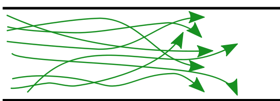
In non-scientific terms, laminar flow is smooth, while turbulent flow is rough. The term laminar refers to streamlined flow in which a fluid glides along in layers that do not mix. The flow takes place in smooth continuous lines called streamlines (Figure 1).

Turbulent flow is a less orderly flow regime that is characterized by eddies or small pockets of fluid particles, which result in lateral mixing.
Laminar flow occurs at lower velocities, and has a more predictable energy loss. Whereas turbulent flow, tends to produce flow instabilities and consequently increased friction losses.
Pipe size
Changing the pipe size for a given volume flow rate will obviously change the gas velocity. The pipe system designer has to strike a practical balance between increasing the pipe diameter to reduce energy loss and keeping the diameter small to lower installation costs.
Density Effects
The shear rate is a measure of a fluid’s viscosity or slipperiness. For fluid flow in a pipe the friction loss is affected by the viscosity of the fluid near the surface of the pipe or duct. The more viscous, or less slippery, a fluid the harder it is to get shearing between layers. The density of a fluid affects its viscosity. Fluids with higher density require more energy to move them and shear less easily.
The specific gravity (SG) of a gas describes its density relative to that of air. When comparing the flow of propane gas (SG of 1.5) to Natural gas (SG of 0.6), the Propane gas would cause a greater pressure loss when all other flow factors are equal.
Pipe Material
A fluid flowing through a pipe contacts the pipe wall. The pipe wall has surface roughness. The amount of roughness affects the drag on the fluid. Piping with smooth interior walls has less resistance to flow than those with rough interior walls. When comparing the flow of a gas through copper tube and carbon steel pipe of the same inside diameter, the steel pipe would cause a greater pressure loss when all other flow factors are equal.
This factor will be accounted for by the use a table or formula, relative to the type of pipe being used. The accumulated length of pipe will then determine the total pressure drop of the piping system.
Fittings
When a fluid is forced to change direction, or go around a disruption, eddies are produced. These new twisting eddies interfere with the flow pattern and produce additional pressure losses. It is important to account for the pressure loss caused by fittings.
There are a number of different methods used to account for the friction loss of fittings, including:
- Percentage of length
- Pressure drop (∆P) calculations
- Equivalent length tables
Percentage of length
Some pipe sizing methods will simply add 10% or 20% to the actual measure length to give an allowance for the additional friction loss created by the fittings. This system makes it even more important to design the piping system with as few fittings as possible, so that the total pressure drop accounted for in the pipe size and length calculations is not exceeded.
Fitting ∆P calculations
The pressure drop of each fitting and valve can also be calculated by the used of experiential data, in the form of resistance constants. These values are available from different sources like tables and diagrams from different sources such as manufacturers. Some example of these constants include; resistance coefficient (K), equivalent length (L/D) and flow coefficient (Cv). These constants are used within various formulas that will also require such information as; flow rate, SG, internal diameter.
Equivalent length tables
To make fitting friction calculations easier the fitting and valve friction loss values are given in tables. The table values are often expressed in terms of an equivalent length of pipe. In other words, each pipe fitting or valve is equal, in resistance, to an equivalent length of straight pipe. This length can be added to the actual length of the pipe, to get an equivalent run of pipe that would include an allowance for the fittings.
 Now complete Self-Test 2 and check your answers.
Self-Test 2
Self-Test 2
- For design purposes the relevant friction loss pressure drop is the difference in gas pressure between the point of gas supply and the nearest appliance.
- True
- False
- As per the Natural Gas and Propane Installation Code book what is the maximum allowable pressure drop in a propane gas piping system with a supply pressure of 14 kPa.
- 250 Pa
- 1.75 kPa
- 7 kPa
- 10 kPa
- Laminar flow is smooth and occurs at low velocities
- True
- False
- Pipe size does not change the gas velocity.
- True
- False
- Which of these listed gasses will have the greatest pressure loss when all other flow factors are equal.
- Natural gas (SG 0.6)
- Air (SG 1.0)
- Propane gas (SG 1.5)
- Butane gas (SG 2.0)
- For piping systems what method can be used to account for the friction loss of fittings?
- Percentage of pipe length
- Pressure drop (∆P) calculations
- Equivalent length tables
- All of the above
Check your answers using the Self-Test Answer Keys in Appendix 1.
Media Attributions
- Figure 1 “Laminar flow patterns” is cropped from “Laminar and turbulent flows” by Dubaj, vectorized by Guillaume Paumier is in the public domain.
- Figure 2 “Turbulent flow patterns” is cropped from “Laminar and turbulent flows” by Dubaj, vectorized by Guillaume Paumier is in the public domain.
