Learning Task 1
Describe the installation of gas piping, tubing and hoses
In this module the use of the term “Piping System” can include any approved pipe, tube, connector, hose or fitting used to convey the fuel gas from the point of supply to the gas burning equipment.
A good quality installation of the piping system is necessary to ensure reasonable life expectancy, durability, and operating performance of equipment and materials.
Code Requirements
The majority of the gas code requirements regarding the installation of piping systems are in Section 6, but there are other rules that apply to the installation throughout the code. Some code clauses will be referenced throughout this learning task, but you will need to be able to find and apply any clause that may pertain to your installation.
Fittings
Section 6 of the gas code identifies the connections that may be used with the different types of approved piping system materials.
Steel Pipe Fittings
All valves, flanges, fittings and gaskets used on steel pipe shall conform to ANSI/ASME B16.3 for threaded connections or ANSI LC-4/CSA 6.32 for press-connections. The pipe shall have tapered threads that comply with ANSI/ASME B1.20.1. When a jointing sealant is used, it shall be certified to CAN/ULC-S642 and must be applied to the male threads of the pipe. Tape must be stretched and applied in a clockwise direction, with a 50% overlap leaving the first two starter threads bare.
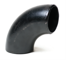
For nominal pipe sizes 2 ½″ and over steel pipe must be connected with welded joints. Manufactured fabricated fittings must be used for welded piping systems (Figure 1) other than large job fabricated headers 2 ½″ NPS and over.
Steel pipe threaded fittings
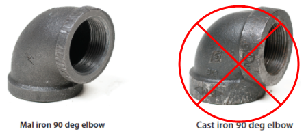
Threaded fittings must be of malleable iron or steel construction, cast iron threaded fittings are not to be used on gas systems as they are more susceptible to cracking. Cast iron threaded fittings can be differentiated from mailable fittings by there heavier reinforcing bead (Figure 2).
All pipe threads shall be clear and free from burrs, scale and defects and the inside ends must be reamed. When a jointing sealant is used for threaded connections, it shall be certified to CAN/ULC-S642 and shall be applied to the male threads of the metal pipe. Tape shall be stretched and applied in a clockwise direction, with a 50% overlap leaving the first two starter threads bare.
Press-connect fittings for steel pipe
There are approved cold press mechanical joint systems designed for use with ASTM A53 carbon steel pipe in gas applications. The press fittings must be installed using the proper tool, actuator, jaws and rings as instructed by the press fitting manufacturer.
The fittings are designed to ensure that any unpressed connections will leak past the internal sealing element. The function of this feature is to provide the installer quick and easy identification of connections which have not been pressed prior to putting the system into operation.
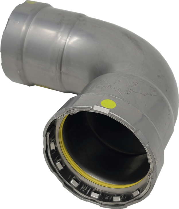
There are steel press fitting available for many applications besides gas, therefore it is important to confirm that the correct fittings designed and approved for gas installations are being used. Notice in Figure 3 the Viega MegaPressG fittings will have a yellow dot or label on the fitting as well the internal sealing element is colour coded yellow.
Prohibited steel pipe fittings
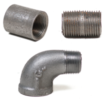
Some types of threaded fittings are not permitted for use with gas systems (Figure 4). These include:
- fittings with running threads, such as thread protectors
- close nipples
- Street elbows
- fittings with right-hand and left-hand threads (not shown).
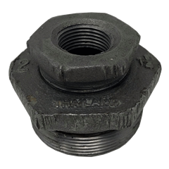
When using threaded bushings, they may be made of malleable iron or steel if they reduce by at least two pipe sizes. If a one pipe size change is to be made with a threaded bushing, it must be done by using a forged steel bushing, as the reduced wall thickness will not be strong enough for the cast malleable material. For example, a threaded ¾″ x ½″ bushing could not be made of malleable iron it would have to be of the steel type. Using multiple bushings together, also known as nesting, is prohibited (Figure 5). Some trades people avoid the use of bushing altogether and prefer t o use reducing couplings.
Copper Tube Fittings
Fittings and connections for copper tubing may be flared, brazed, press- connected. Some compression fittings may also be accepted by the authority having jurisdiction.
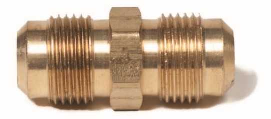
The flare fitting for gas copper tubing systems, using soft annealed copper, are of the SAE 45 degree type (Figure 6). Flare fittings do not come complete with nuts these must be ordered separately.
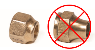
Flared nuts must be of the brass forged type (Figure 7 left). Externally machined nuts (Figure 7 right) may not be used as they are not as strong, due to their decrease wall thickness from the machining process.
CSST Fittings
CSST gas supply systems must get proprietary certification, therefore only manufacturer’s certified fittings may be used for each brand of CSST tubing.
CSST tubing is connected using self-flaring brass fittings that creates a metal to metal seal when tightened. The fitting in Figure 8 was previously tighten and was disassembled to show how the tubing gets compressed to create a double flare. Adapter fittings have standard NPT threads and may be used in combination with other approved fuel gas piping fittings.

PE Fittings
PE pipe installed for underground distribution mains and service lines is assembled primarily with heat fusion, this work is not regulated by the CSA B149.1 gas code. PE may also be used as an underground pipeline on the premises, for example, to supply a separate outbuilding or a firepit.
Fusion fittings may also be used for on premise installations. For gas contractors that may not want to invest in cost of the fusion equipment for the small number of underground installation they may have, there are approved PE compression slab lock fittings (Figure 9) available for sizes 2″ IPS and under.
Manual Shut-Off Valves
Approved appliance manual shut-off valves are required for each appliance and must be readily accessible. Where it is acceptable to the authority having jurisdiction, systems using a distribution manifold may have all the identified appliance shut-offs at the manifold. Manual shut-off valves must also be installed upstream, of any line pressure regulators that are in the system, or were system supplies an underground section of plastic piping. Manual shut-off valves must be of the quarter turn style. Plug, ball or eccentric types (Figure 10) are approved as long as they rated for the pressure and temperature they are being used for.
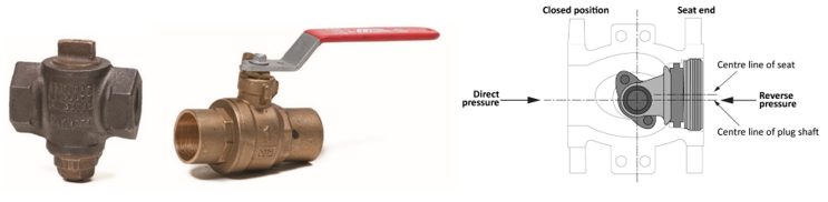
Ball valve are the most common type used, lubricated plug valves are typically found at the utilities meter set. The eccentric styles types are usually only seen on large applications over 2″ in size, the offset half plug creates less friction giving the lower operating torque needed for large valves.
Gas Quick Disconnects
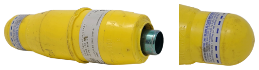
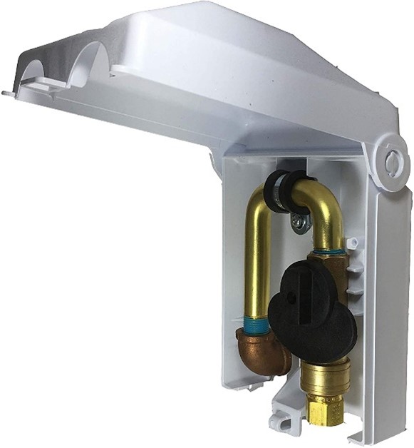
Some appliances that are connected with a gas connector or hose may be approved to have a quick-disconnect device used. Even though the quick-disconnect device has an internal shut-off an additional manual shut off valve must be installed upstream of the quick-disconnect devoice. Additionally, some appliances or locations may require a gas convenience outlet. A gas convenience outlet is a combined unit with the quick disconnect and manual shutoff valve supplied as a unit (Figure 11) certified to ANSI Z21.90/CSA6.24. The manually operated gas valve has the additional feature of a handle designed so that disconnection can be accomplished only when the gas valve is in the closed position.
Drip and Dirt Pockets
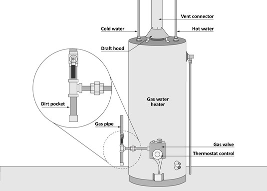
Depending on the type of appliance a dirt pocket may be required at the inlet to an appliance regulator or at the base of a vertical drop to an appliance. The dirt pocket is designed to capture dust before it enters the appliance to reduce the chance of clogged gas valves or orifices.
A drip pocket shall be provided at all points in a piping system where condensation can collect, such as points where the piping is exposed to either wide ranges or sudden changes in temperature.
The names drip and dirt pockets are often used interchangeable because they are built and sized in the same way, by using threaded fittings so that the section below the tee can be removed for cleaning or draining (Figure 12).
Anchors and supports
Piping or tubing must be mounted, braced, and supported to provide for expansion, contraction, jarring, vibration, and settling, so there is no wear or strain on the piping. For each piping installation, you’ll be required to select and install the appropriate types of hangers and supports. Many factors must be considered when selecting pipe supports.
- Refer to job specifications for the correct type of hanger.
- Refer to table 6.2 of the B 149.1 Gas Installation Code for the minimum spacing of supports.
- Piping must be installed with individual supports and may not be supported by other piping
- Identify the piping material regarding contact between the hanger and the material the hanger is made of. Contact between dissimilar metals can result in electrolytic action between hangers and piping.
- Identify the type of building structure materials that the hanger will be fastened to. For example, attaching to concrete, metal, or wood.
- Select the correct size and type of fastener and the method and tools used to install the fastener. For example, wood screw, lag screw, bolts, or beam clamp.
- Refer to the manufacturer’s maximum load capacity requirements for each hanger and fastener.
- If seismic restraint/sway-bracing is required
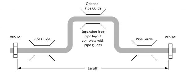
For long straight runs of exposed piping such as on commercial or industrial roof tops there are additional considerations needed to accommodate the pipe movement caused by thermal expansion and contraction. This may be obtained by the use of designed pipe bends, loops (Figure 13), offsets, expansion, joints. The piping will need to be anchored at appropriate locations to control the direction of expansion and contraction. Annex G of the Gas code gives examples of an acceptable expansion loop design for pipe sizes 2″ or less up to 100 feet in length.
For roof top installations the piping may be supported with treated wood blocks or material having at least equivalent characteristics as wood blocks. The support spacing for piping NPS 1 and greater shall comply with Table 6.2 and support must be provided for every threaded fitting. Horizontal roof top piping less than NPS 1 must be supported every 4 ft (1.2 m), and all tubing must be supported continuously.
Structural Penetrations
Much of the gas pipe and venting you install will penetrate through walls, floors, ceilings and roofs. You may need to consult with the manufacturer’s specifications, regulatory codes, inspection authority and design engineer before making structural penetrations.
Exterior Penetrations
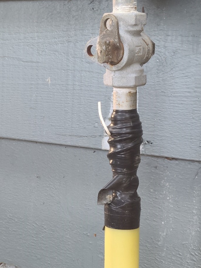
Gas piping should not enter the building from underground it must rise above grade before entry unless otherwise permitted by the authority having jurisdiction. When gas piping or tubing passes through an exterior wall above ground, it must be sealed watertight and the portion of piping that runs through the wall shall be sleeved or double wrapped with a waterproof wrap.
Interior Penetrations
When installing gas piping systems, you must maintain the integrity of the structure. You cannot simply remove cut, notch, drill or otherwise alter a building’s structural components without considering the effect you are having on that structural component’s purpose.
On the job you will need to reference the building code and specific manufacturer’s specifications for drilling and cutting of building framing.
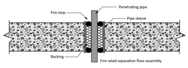
Fire separations
A fire separation is a construction assembly that acts against the spread of fire. A fire separation is constructed of components that make up a fire-rated assembly or system. The fire rating of each component in the assembly contributes to the final fire rating for the fire-separation assembly.
It is critical that the gas piping systems, and vents do not compromise the integrity of the fire separations, walls and stops. When gas systems penetrate into or through, or are installed in a fire separation, the pipes or vent penetrations will need to be installed with an approved firestopping method (Figure 14) to ensure the integrity of the fire separation. The installation of firestop systems and the penetration of piping through structural components often involve the manufacturer’s design installation.
Location Limitations
Many of the location limitations identified in the gas code are related to the obvious hazards associated with the potential accumulation of pockets of fuel gas within a building. Any joints or fittings that are going to be concealed must be tested and inspected before they are covered over.
Gas piping or tubing can not be installed in the following locations:
- A stairwell other than a stairwell within a dwelling unit, unless it is totally enclosed by a chase consisting of material that has the same fire-resistance rating as that required for the stairwell.
- A chimney, flue, elevator shaft, dumbwaiter, or chute.
- A heating or ventilating plenum, duct, or shaft. The only exception to that gas piping may be installed in a false ceiling space, including one used as a return-air plenum of a central warm-air or air-conditioning system
- In contact with either cinders, ashes, or other corrosive materials.
- In a conceal location where a corrosive chemical is used.
- Underground piping or tubing shall not pass below a foundation or wall, or under a building.
If gas piping or tubing is to be installed in solid flooring, such as concrete, it must be laid in channels and suitably covered to permit access to the piping or tubing. Alternatively, the piping or tubing shall be encased in ventilated ducts so that there is free air space around the pipe or tube.
Each vertical piping chase shall have an opening at the top and bottom, and the opening shall have a minimum area equivalent to a round opening of 1 in (25 mm) in diameter.
Protecting Piping
There are many factors that can cause damage to piping. Damaged pipe will result in reduced life expectancy or failure of the piping system. Pipe can deteriorate for many reasons including installation practices, environment conditions. This damage can be reduced by protecting the pipe when selecting and installing gas piping systems.
Basic methods used to protect piping and piping systems include:
- protective coatings
- physical and mechanical damage protection
- cathodic protection
Protective Pipe Coatings
Outdoor piping, or indoor piping and tubing that is exposed to atmospheres that are corrosive to the piping or tubing, must be protected by either painting or coating. Because of the exposure to sunlight and rain or snow, coated or wrapped gas piping is not recommended.
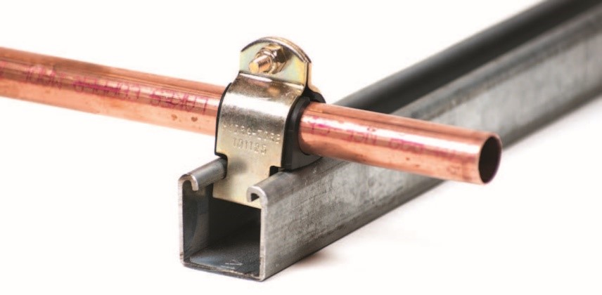
To avoid galvanic corrosion, metallic piping or tubing shall be installed in such a manner that it is not in contact with any other dissimilar metal. This includes supports of dissimilar metal which will need to be lined or insulated from the gas pipe (Figure 15).
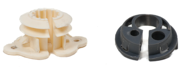
Or were copper tubing is installed in steel stub walls it should be wrapped with electrical tape or use plastic grommets (Figure 16) to avoid contact with the steel studs.
Masonry or concrete can be very corrosive when in contact with piping and tubing, therefore the portion of piping or tubing that runs through this material must be sleeved or double wrapped with a pipe wrap tape.
Physical and mechanical damage protection
All gas piping must be protected against either damage or breakage due to strain, wear, and mechanical impact. There are many potential hazards that may required additional piping protection.
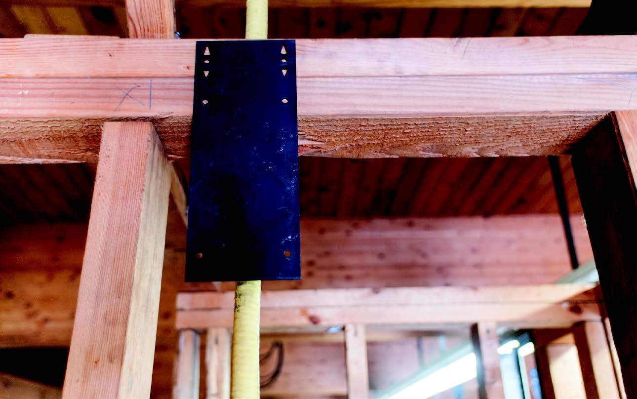
Tubing run in hollow walls can be punctured so striker plates or some other protection will be required if the tubing is near the surface (Figure 17).
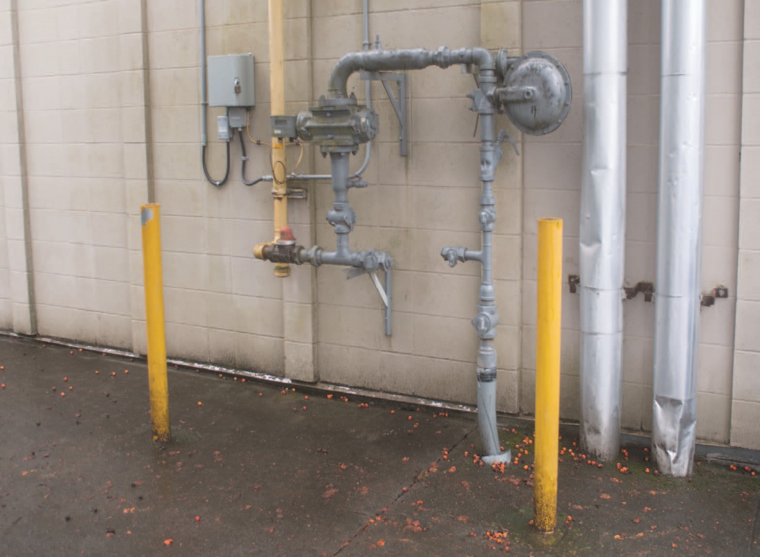
Posts or guard rails will need to be installed to protect the piping from vehicular traffic in locations where services enter a building at a street or parking lot (Figure 18).
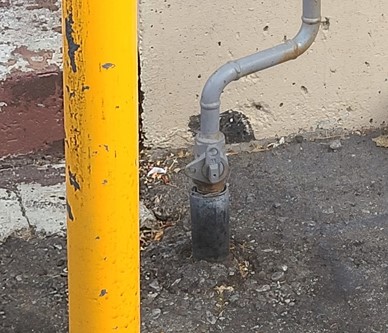
When piping or tubing is laid under pavement where it comes through the pavement a sleeve will need to be installed to permit free movement of the soil and covering without placing strain on the piping or tubing (Figure 19).
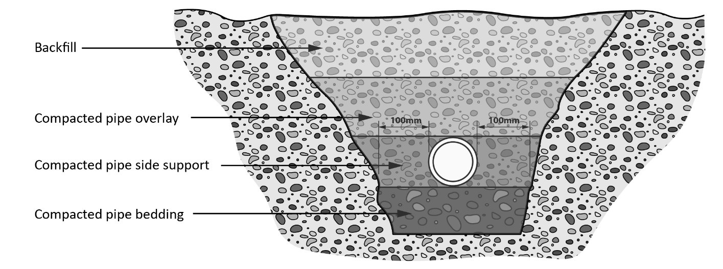
Underground gas piping must be laid so there are no sags or strains piping, which may require the installation of compacted bedding material. This and proper backfill material must be used that is free of sharp objects, large stones, or any other material that can damage the piping or tubing (Figure 20).
For the purpose of locating the underground pipeline all plastic piping or tubing must have a yellow poly coated tracing wire. or other approved electronically detectable tracing method such as magnetic tape, buried alongside the pipeline. The tracer wire should be laid within 6 inches of the plastic pipe where practical and directly above if possible. The ends of the tracer wire shall have easily accessible above ground termination points for connecting the electronic tracing equipment (Figure 21).
When steel gas pipe is buried additional corrosion control measures are required.
Underground Piping Corrosion Protection
Electrochemical corrosion occurs when two dissimilar metals are in contact with each other in a moisture-rich environment. Although this can happen anywhere, it’s especially problematic for buried steel pipe. One metal becomes a cathode, and the other (usually the pipe) becomes an anode that corrodes and develops a leak. Although corrosion cannot be eliminated, it can be substantially reduced with proper protection. There are three methods of protecting underground piping from corrosion:
- protective coatings
- cathodic protection.
- electrical insulation
Underground protective coatings
Protective coatings insulate a pipe from the soil (the electrolyte). A good coating has a high dielectric strength — that is, it is a good electrical insulator. It adheres tightly to the pipe and has the necessary mechanical strength to withstand handling, soil stresses, and any tendency towards cracking.
Yard-applied coal tar and extruded polyethylene are the main coatings used. While most coatings absorb some water and allow some current to penetrate through to the steel surface, for most practical purposes, the steel is considered isolated from the soil.
In theory, this would be enough to prevent corrosion; however, it is virtually impossible to install a pipeline without some defects in its coating. The portions of pipe that become exposed to the soil as a result of damage to the coating corrode quickly because the corrosion is concentrated in those areas.
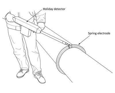
The integrity of the pipe coating can be tested for areas were pipe is not protected, these areas are known as a Jeep or Holiday. The Jeep meter (Figure 22) is an electronic testing unit that finds these imperfections so that they can be repaired before the piping is buried.
Methods of cathodic corrosion protection
All metals have a known electrical value on an electromotive scale. If two metals have different electrical potential, a current will flow between them. The current always flows from active metals (metals with higher potential) to less active metals (metals with lower potential).
Four things are necessary for galvanic corrosion to occur. They are:
- an anode
- a cathode
- an electrolyte
- a conductive path.
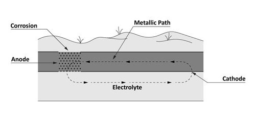
The current flows between metals of differing potential regardless of whether the metals are close together or far apart (Figure 23).
For galvanic corrosion to occur there must be a complete electrical circuit. The electrical current travels from the anode to the cathode in the electrolyte.
The simplest method of protecting against galvanic corrosion is to connect the protected metal to a sacrificial metal that acts as the anode in the electrochemical cell. The sacrificial metal corrodes instead of the protected metal.
There are two basic methods of cathodic protection:
- passive galvanic anode system
- impressed current system
Passive galvanic anode system
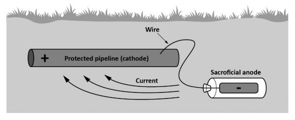
Anodes are usually installed near the pipe and connected to the pipe with an insulated conductor. They are sacrificed (corroded) instead of the pipe. Anodes are “sized” to meet the electrical current requirements of the soil. Anodes are made of materials such as magnesium (Mg), zinc (Zn), or aluminum (Al).
The sacrificial anode consists of a bag containing either magnesium or zinc ingot and other chemicals and is connected by wire to an underground metal piping system. It functions as a battery that induces a direct current on the piping system to retard corrosion (Figure 24).
Impressed current systems
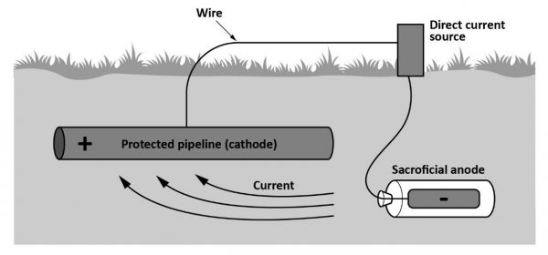
For structures where passive galvanic corrosion protection is inadequate (e.g., long pipelines), an external DC electrical power source is used to provide current. This direct current is induced onto the pipe by means of a rectifier (Figure 25).
These systems are normally used along transmission pipelines where there is less likelihood of interference with other pipelines. Anodes made of corrosion-resistant material such as graphite, high-silicon cast iron, lead-silver alloy, platinum, or scrap steel are used to disperse the electric current. The DC rectifier will typically have a DC output of between 10 and 50 amperes and 50 volts, depending on the system requirements.
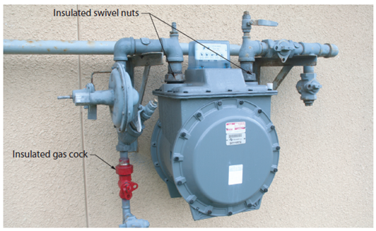
Electrical Insulation
For piping systems with cathodic protection, the current is regulated to follow a specific electrical path. A protected piping system must be electrically insulated from other metallic structures to prevent stray electrical currents from affecting the protected underground pipeline. This is accomplished by installing a dielectric fitting on the pipeline directly outside the building wall. This prevents electrical contact between protected piping (underground) and unprotected piping (above ground). This fitting is usually an insulated union, insulated flange, or insulated meter spud (Figure 26).
Identification of Gas Piping
Pipe markers should be added to all piping systems to identify the contents of any section of piping in a facility. The primary visual indicator of a pipe marker is the colour. ASME defines the colour codes by hazard classifications. All flammable or oxidizing fluids or gas are labeled yellow with black text.
In addition to the color-coding scheme mentioned above, the standard ANSI/ASME A13.1 also includes requirements for the content, sizing, and placement of pipe markers. Additionally, section 6.17 of the B149.1 gas code specifies the minimum requirements based on the type of building and the pressure in the gas system.
 Now complete Self-Test 1 and check your answers.
Self-Test 1
Self-Test 1
- Which of the following cannot be used in a gas piping system?
- Street elbow
- Close nipple
- Thread protector couplings
- None of the above are permitted
- For steel press-connect fittings used on gas systems the internal sealing element is colour coded red.
- True
- False
- Flared nuts used on gas systems may be of the brass forged or machined type.
- True
- False
- Flare fittings for all copper tubing are base on what tube dimension?
- ID
- OD
- CTS
- Both OD and Nominal size
- On an underground catholically protected piping system the pipe will be considered what component?
- Anode
- Cathode
- Electrolyte
- DC source
The answers for the following questions can be found in Section 6 of the B 149.1 Gas Installation Code.
- When tubing is run in hollow walls or partitions it must be protected by 16 gauge plates or sleeves if it is within a minimum of _______ inches of the wall’s surface.
- 0.75″
- 1.00″
- 1.50″
- 1.75″
- Gas lines installed underground must be buried a minimum of what distance?
- 12″
- 15″
- 18″
- 24″
- What is the maximum permitted spacing for horizontal support of 1 ¼″ NPS black iron gas pipe?
- 6 ft.
- 8 ft.
- 10 ft.
- 12 ft.
- What is the maximum permitted spacing for horizontal support of 1″ OD copper gas tubing?
- 6 ft.
- 8 ft.
- 10 ft.
- 12 ft.
- When penetrating a floor with a gas line, what minimum distance must the un-threaded portion extend through the floor?
- 25 mm
- 50 mm
- 75 mm
- 100 mm
- What is the minimum depth required for a drip pocket or dirt pocket?
- 2″
- 3″
- 4″
- 6″
- What is the maximum diameter required for a drip pocket or dirt pocket?
- 1″ NPS
- 2″ NPS
- 3″ NPS
- 4″ NPS
- May a quick-disconnect device be used as a substitute for a manual shut-off valve?
- Yes
- No
- What is the maximum spacing permitted for identification of tubing systems in residential buildings?
- 2 m
- 3 m
- 4 m
- 6 m
- What is the maximum permitted length of an approved hose that may be used to connect a construction heater to the gas supply?
- 20 ft.
- 50 ft.
- 75 ft.
- 100 ft.
Check your answers using the Self-Test Answer Keys in Appendix 1.
Media Attributions – TO BE REORGANIZED
- Figure 1 “Carbon steel butt-weld Sch40 90 deg elbow” by Trades Training BC is licensed under a CC BY 4.0 licence.
- Figure 2 “Malleable iron to cast iron bead comparison” by Trades Training BC is licensed under a CC BY 4.0 licence.
- Figure 3 “Viega MegaPressG elbow” by Camosun College is licensed under a CC BY 4.0 licence.
- Figure 4 “Prohibited nested bushings” by Camosun College is licensed under a CC BY 4.0 licence.
- Figure 5 “SAE Flare union” by Trades Training BC is licensed under a CC BY 4.0 licence.
- Figure 6 “Forged and externally machined nuts” by Trades Training BC is licensed under a CC BY 4.0 licence.
- Figure 7 “CSST ½″ straight fitting” by Trades Training BC is licensed under a CC BY 4.0 licence.
- Figure 8 “Gas compression stab fittings” by Camosun College is licensed under a CC BY 4.0 licence.
- Figure 9 “Approved manual gas shutoff valves – plug and ball” by Trades Training BC is licensed under a CC BY 4.0 licence.
- Figure 10 “Approved manual gas shutoff valves – eccentric” by Camosun College is licensed under a CC BY 4.0 licence.
- Figure 11 “Gas convenience outlet” by Camosun College is licensed under a CC BY 4.0 licence.
- Figure 12 “Appliance dirt pocket” by Camosun College is licensed under a CC BY 4.0 licence.
- Figure 13 “Expansion loop with guides and anchors” by Trades Training BC is licensed under a CC BY 4.0 licence.
- Figure 14 Typical parts of a firestop by Trades Training BC is licensed under a CC BY 4.0 licence.
- Figure 15 “Copper tube support with isolative capability” by Trades Training BC is licensed under a CC BY 4.0 licence.
- Figure 16 “Plastic grommets” by Trades Training BC is licensed under a CC BY 4.0 licence.
- Figure 17 “Striker plate protecting CSST tubing” by Trades Training BC is licensed under a CC BY 4.0 licence.
- Figure 18 “Pipe bollards filled with concrete protecting gas piping” by Trades Training BC is licensed under a CC BY 4.0 licence.
- Figure 19 “Sleeved gas service pipe” by Camosun College is licensed under a CC BY 4.0 licence.
- Figure 20 “Example of properly backfilled underground pipe” by Trades Training BC is licensed under a CC BY 4.0 licence.
- Figure 21 “PE Sleeved meter riser with tracer wire for PE tracing” by Rodney Lidstone, Camosun College is licensed under a CC BY 4.0 licence.
- Figure 22 “Jeep test” by Camosun College is licensed under a CC BY 4.0 licence.
- Figure 23 “Corrosion of an underground metallic pipe” by Camosun College is licensed under a CC BY 4.0 licence.
- Figure 24 “Passive anode system” by Trades Training BC is licensed under a CC BY 4.0 licence.
- Figure 25 “Impressed Current Systems” by Trades Training BC is licensed under a CC BY 4.0 licence.
- Figure 26 “Gas service with insulated unions” by Trades Training BC is licensed under a CC BY 4.0 licence.
