Learning Task 2
Describe Atmospheric Burners
An atmospheric burner is a simple device that requires no fans or electrical supply, and it is designed to burn gaseous fuels efficiently and simply. It is one of the most common types of burners found in residential and commercial equipment, although many appliances have moved towards various types of mechanical burners.
Flame Characteristics
Atmospheric burners can be either a “luminous burner” or a “Bunsen burner”, each having its own unique characteristics.
Luminous Burner
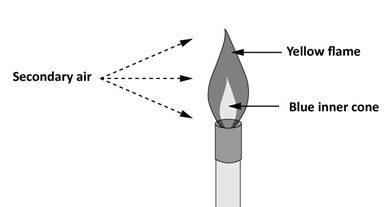
A luminous flame burner does not premix gas and air before ignition and consequently the flame depends upon the air around the flame (secondary air) for combustion. When the gas is heated inside the flame without air, the hydrogen and carbon particles separate. The flame has a small blue inner cone created by the hydrogen burning at a greater speed and a lower temperature than does carbon. The slower burning carbon, because of their higher temperature, produce an incandescent light creating a large glowing yellow flame (Figure 1). This type of burner is used in decorative appliances and appliances that are designed to give off light.
Bunsen Burner
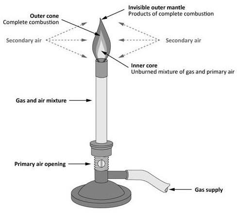
Most atmospheric burners today use a Bunsen flame, named after Robert Wilhelm Bunsen who discovered that premixing air with the gas before it is ignited produced a much more efficient flame. The flame is blue in colour, non-luminous, smaller in size and has a higher temperature. The bright blue flame is the result of premixing primary air with the fuel. The remainder of the air necessary for combustion is supplied by the secondary air, from around the flame. A stable atmospheric Bunsen burner flame has several color zones. Each of these zones (Figure 2) marks a stage in burning of the gas.
Inner cone
On the burner tip, or port, is a thin, blue cone called the inner or primary cone. The inner cone marks the first step in the burning process where gas is burned to form products such as aldehydes, alcohols, carbon monoxide, and hydrogen. The velocity of the unburned gas-air mixture forms the shape of the inner cone. Inside the inner cone is a darker area, an unburned, fairly cool gas-air mixture.
Outer cone
The inner cone is surrounded by a darker outer cone. At the outer cone secondary air around the flame diffuses into the flame to take part in the burning. If enough secondary air is present and other conditions are favourable, products from the inner cone are completely burned here, yielding the final products, carbon dioxide and water vapour. Highest flame temperatures usually occur at a point just above the outer cone.
Outer mantle
A colorless mantle surrounds the outer cone. Since burning is usually completed at the outer cone, there are almost no unburned gases at the outer mantle. This nearly invisible mantle only glows because of the combustion products’ high temperature.
Types of Bunsen flames
The primary air supply sets the Bunsen flame characteristics. If the proper amount of primary air is premixed with the gas, the burner will provide a stable blue flame. Adjustments to the air supply will cause the flame to change shape and color. These changes result in one of three types of flames:
- Reducing flame
- Oxidizing flame
- Neutral flame
The reducing flame is a flame with low oxygen. It has a yellowish color due to the presence of unburned carbon or hydrocarbons. The reducing flame is also called a carburizing flame, since it tends to introduce carbon into molten metal when being used for welding or brazing operations.
An oxidizing flame is the flame produced with an excessive amount of oxygen. When the amount of oxygen increases, the flame shortens, its color darkens, and it hisses and roars. The oxidizing flame is usually undesirable for welding and soldering, since, as its name suggests, it oxidizes the metal’s surface.
The neutral flame is the flame in which the amount of oxygen is precisely enough for burning, and neither oxidation nor reduction occurs. This flame has a good balance of oxygen and is clear blue.
Flame Impingement
If a cold surface touches (impinges) the bright blue inner cone of the Bunsen flame it will reduce the temperature and cause incomplete combustion. Soot forming on the colder surface is an indicator of this condition.
Impingement of the outer cone will not cause incomplete combustion because the heat from the inner cone maintains the temperature required for combustion. This principle is sometimes used in burners to reduce flame temperatures and lower NOx levels.
Flame retention
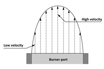
Flow velocity is not the same at all points across a burner port. At some distance above the burner port, the flow velocity equals burning speed, and the flame stabilizes at that point. Since flow velocity is highest at the port centerline, the flame stabilizes the furthest from the burner port around the centerline. The flame also stabilizes at lower points near the burner port walls, were the friction slows down the flow velocity. When the flow velocities across a burner port are shown as arrows (Figure 3) you can see why the inner flame assumes its typical conical shape. Burner ports can be designed to increase the gas volume and still create a low velocity area for the flame to anchor or retain itself. Otherwise the flame will lift from the port and possibly extinguish itself.
Burner Operation
All atmospheric burners are designed to provide complete combustion, stable flames, and quiet operation. To understand fully how an atmospheric burner operates, let’s look at the burner components and how they operate.
Burner Parts
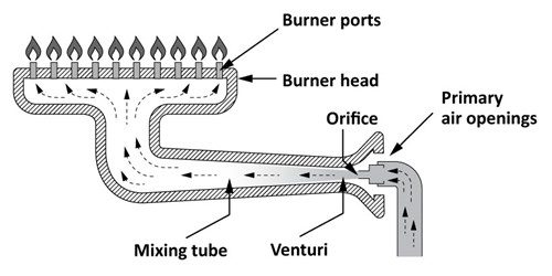
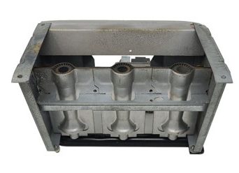
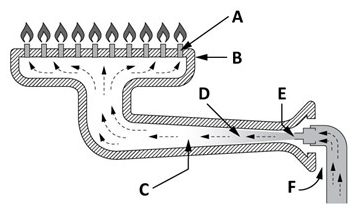
Gas burners have many different shapes, sizes, and styles but they all have essentially the same components (Figure 4).
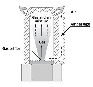
Venturi
The venturi is a short tube with a constricted, throat-like passage. This narrowing passage increases the velocity and creates a negative pressure in relation to the air surrounding the burner. Due to the negative pressure, atmospheric air is sucked in and mixed with the high velocity gas flow.
Recall Bernoulli’s Theorem
For any given flow rate:
- when velocity increases, the pressure decreases
- when velocity decreases, the pressure increases.
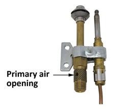
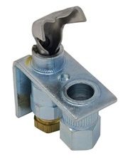
Primary air openings
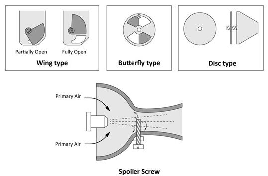
Some burners are furnished with fixed primary air openings, and may have a device to adjust primary air, such as an air shutter. This shutter is used to adjust the size of air openings to control primary air flow.
Primary air control devices can take a variety of forms. Some of the more common types are wing, butterfly, rotating or sliding disc and spoiler screw.
Orifice
Technically the orifice is not part of the burner, but it is such a vital part of the burner system that it is included in the explanation of burners. The gas enters the burner through the orifice and the combination of the gas pressure and the orifice size controls the volume and velocity of gas being injected into the burner. Adjusting the gas supply (manifold) pressure will change the velocity of the gas stream and the venturi affect, thereby changing the amount of primary air being drawn into the burner. A good example of that is the fact that a typical atmospheric burner may operate at manifold pressure of approximately 4” WC when firing on natural gas, but that same burner when converted (re-orificed) to operate on propane will have the manifold pressure adjusted to approximately 10” WC. The higher pressure is needed to draw in the greater ratio of primary air required for the propane gas.
Mixing tube
The mixing tube is the portion of the burner that lies between the venturi and the burner head. The gas and primary air mix together as they move along this tube.
Burner head
When the gas/air mixture enters the burner head (the point where the area is greatest) the velocity is at its lowest point and therefore, the pressure is at its highest point within the burner. The increased pressure will allow the gas/air mixture to be uniformly distributed to the burner ports with enough velocity to match the flame speed of the fuel gas. Its size and shape can be tailored to fit an appliance combustion chamber and to provide even heat release to the heat transfer surfaces.
Burner ports
The burner port is an orifice, or opening, that does three things:
- discharges the air-gas mixture for ignition
- distributes flames to provide an even heat transfer to the heat exchanger
- spreads the flames so they can be reached by secondary air.
Burner Adjustments
A properly functioning burner should have the following characteristics:
- Uniform heat distribution and flame height, with good flame distribution over the burner area.
- Complete combustion, where neither carbon nor carbon monoxide escapes from the flames.
- Stable flames that do not lift away from the burner ports.
- Ready ignition where the flame travels rapidly and easily from port to port over the entire burner.
- Quiet operation during ignition, burning, and on extinction.
As a general rule, simple adjustments can make a properly designed burner work satisfactorily under changing service conditions. A small hard blue flame or a flame blowing off the burner ports or lighting back at the burner orifice indicates too much primary air and the air shutter should be closed. A soft, blurred or yellow tipped flame indicates lack of primary air and the air shutter should be opened.
Types of Burners
Burners are designed in many shapes and sizes to accommodate the wide variety of heat exchangers and combustion chamber requirements.
There are two main categories of atmospheric burners used on gas appliances:
- Main burners
- Pilot burners
Main Burners
There are two common types of atmospheric main burners:
- Single port
- Multiport
Single port burners
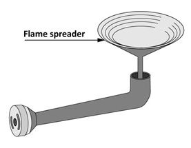
Single port or Mono-port burners consist of a single pipe or single nozzle of the inshot or upshot design. An inshot burner usually fires horizontally and the gas burns on the end of the straight extension of the mixer tube (Figure 6). A flame spreader is sometimes used to deflect the flames in a predetermined pattern.
In an upshot burner, air-gas mixture flows through a bend and into a riser tube where it burns vertically. These are common in domestic storage type water heaters.
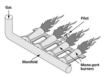
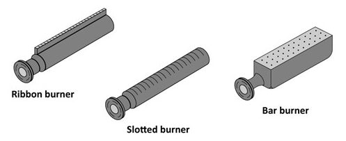
Multiport burners
The multiport burner is the most common atmospheric burner used in appliances. There are a number of different shapes and types of multi-port burners including; drilled ports, ribbon burners, slotted port, or bar burners (Figure 8).
When a number of these burners are used together as shown in Figure 9, it is referred to as a burner bed.
Pilot Burners
The primary function of a pilot burner is to ignite the main burner flame. No one pilot burners design can give an adequate ignition flame for all types of main burners. Consequently, there are many different pilot burner designs with a wide selection of mounting styles and directional hoods. Most pilot burners may also serve as a component in the flame safety circuit and are monitored by a device that shuts off the gas supply to the main burner if the pilot flame is extinguished.
Pilot burners are often described by either; their ability to premix primary air or their ignition sequence. The ignition sequence will be described in Competency E-6 Select Flame Safeguards
Pilot burner aeration
Pilot burners, as with main burners, can be categorized according to their ability to premix gas with air. Consequently, two basic types of pilot burners are; aerated pilots and non-aerated pilots.
Aerated pilots
Aerated pilots premix air and gas, and therefore develop a sharp blue flame. These pilots have a relatively stable flame and are not normally affected by draft or main burner variations. Aerated pilots produce higher flame temperatures making them good for use with heat activated safety devices, such as a thermocouple (Figure 10).
The most common problem associated with aerated pilot burners is clogging of the primary air openings due to dust and lint. This is especially true for burners that are near the floor, such as water heaters. An aerated incinerating pilot, can help combat the dust problem. This type of pilot draws the primary air through a tube or air duct (Figure 11). This tube passes around the pilot flame, incinerating any lint or dust that could be in the primary air.
Non-aerated pilots
Non-aerated pilots have a softer flame which sometime includes a little yellow colouring. The non-aerating pilots do not have the same dust and lint problems as the aerated pilots, but they can be affected by draft and main burner variations. A deflector target will often be used to direct the flame toward the main burner port and shield the pilot flame
To create the similar stable characteristics of an aerated pilot the target shield will have a tapered shape to create a venturi effect on the secondary air and improve the mixing of the air and gas (Figure 12).
Troubleshooting Atmospheric Burners
The most common problems associated with atmospheric burners are:
- Flashback
- Extinction Pop
- Flame Liftoff
- Floating Flames
- Waving Flames
- Flame Roll Out
- Yellow Tipping
- Fluctuating Flames
- Gas odour
Flashback
When flashback occurs in a burner, the gas/air mixture ignites inside the burner to burn near the orifice. This burning in the mixing tube usually creates a roaring noise like a torch.
Any flashback condition must be avoided as prolonged burning inside the burner can cause damage to the burner as well. The burning action inside the mixing tube will not get enough air, and cause incomplete combustion producing carbon monoxide and aldehydes. Incomplete combustion can also produce free carbon (soot), which clogs the inside of the burner.
Remedies for flashback
Flashback on ignition or during burner operation can be caused by a very lean gas/air mixture and can be usually eliminated by reducing the primary air to the burner. Make sure the air adjustment does not produce yellow-tipping of the flames. The burner may be underfired, so check the input rate and adjust it to its correct value (orifice size and manifold pressure), if necessary. The orifice size may need to be enlarged, or the gas pressure increased, if the input is found to be too low.
Sometimes only one burner of several in an appliance flashes back, such as in a multi-sectional furnace. Check the orifice size of that burner. If flashback occurs with the gas valve in the OFF position, the valve is probably leaking. Experience has shown that sticking valves which are slow opening and/or closing may cause flashback. Replace the valve. The burner ports themselves may require cleaning. Be sure not to enlarge or deform the burner ports. Replace the burner or burners if the above corrections fail to eliminate the flashback.
Extinction Pop
Sometimes a type of flashback occurs when the burner is shut off. This problem is commonly called “extinction pop”. Extinction pop, as the name implies, creates a noise or a “bang”. Ordinarily, it is not followed by burning in the burner head or mixing tube, since the gas supply is turned off. The pop occurs when the gas supply to the burner is shut off, or sometimes it may be delayed for a few seconds.
Ordinarily, extinction pop is not unsafe or hazardous, and will not damage the appliance. It may result in a customer complaint because of the noise created. However, the explosion may blow out the pilot flame. If an automatic pilot safety device is used to sense the pilot flame, it will shut off the gas supply to the appliance.
Remedies for extinction pop
It may be possible to eliminate extinction pop by reducing the primary air supply to the burner, due to the fact that a lean mixture may exist at the burner port with a richer mixture inside the mixing tube when the gas supply is shut off. This can be a common problem on long atmospheric burners. Make sure to check for proper manifold pressure and orifice size. Cleaning of the burner and/or orifice may be required. If these actions fail to correct the problem, a burner change may be required.
Flame Liftoff
When flame liftoff occurs, part of the flame lifts or “dances” on the burner port. Lifting flames may occur on a few or on all of the burner ports. If flames lift from a number of burner ports, they may create a distinct flame noise. Lifting burner flames result when the flow velocity of the gas/air mixture from a burner port is greater than the flame burning speed. The flame cannot stabilize on or just slightly above the burner port, as in normal operation.
Lifting flames which create a roaring noise in an appliance can lead to customer complaints. Of a more serious concern, products of incomplete combustion may escape the flames if the flame cones rupture. Unburned gas may also escape, reducing the appliance’s efficiency.
Remedies for lifting flames
Any operating factor or burner design factor which increases flow velocities may be the cause of flame lifting. The simplest way to stop burner flames from lifting is to reduce the primary air. However, before doing this always check that the appliance input is correct, the orifice size and/or the manifold pressure may need to be reduced first. Flame lifting on pilot burners is often a result of high gas pressure
Flame lifting may only be on one of several burners in an appliance. Check the orifice size of that burner to make sure it is not being overfired. When reducing the primary air to stop the flames from lifting, do not reduce it to the point that yellow-tipping occurs.
Floating Flames
The term floating flame often causing confusion with lifting flames but they are quite different, as are the causes and corrective steps. As previously described flame liftoff has lifting or blowing flames that are well defined and hard, and may create a blowing noise, whereas floating flames are lazy looking. They do not have well-defined cones and appear to be “reaching” for air. Use extreme caution when removing access doors or inspection doors while the burners are operating. The sudden supply of oxygen could cause the flames to blow through the doors. The flames are long, undefined and quiet and tend to roll around in the combustion chamber, sometimes completely off the burner ports (Figure 13). Usually a strong aldehyde odour is present.
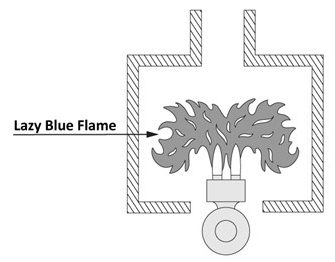
Floating flames almost always indicate incomplete combustion. Floating flames are a dangerous condition, which require immediate attention. If there is an inadequate supply of secondary (and excess) air the burner flames will float. Combustion products will recirculate lower in the combustion chamber. These products contaminate the air supply, adding to the problem. If the appliance utilizes a pilot for main burner ignition, it will often smother and go out. The flame safeguard will then shut off the gas supply and stop any further incomplete combustion. This will indicate a problem which must be corrected immediately.
Remedies for floating flames
A lack of combustion air causes burner flames to float. Several conditions or a combination of these conditions can be the cause. The appliance may be overfired. If so, the flue outlet provided for the rated input may be too small to handle the increased flow rate. Check the appliance input rating and reduce it if necessary.
Floating flame can be a result of poor venting, check for blockages at the flue collar of the appliance if it is equipped with a draft control device. If the appliance is not equipped with a draft control device, a blockage anywhere in the venting system could cause floating flames check causes of poor venting. Check for blockages at the burner ports and clean them if necessary. Adjust the primary air to get rid of any yellow tipping which may have produced soot to block the flue passages. Make sure combustion air inlet openings are clean and are not blocked. Contamination of the air supply may cause flames to float.
Waving Flames
Waving flames is another expression that must not be confused with flame lifting or floating flames. This condition is a result of drafts across burners which can cause flames to waver or appear to be unstable (Figure 14).
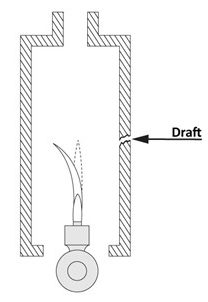
Waving burner flames can lead to incomplete combustion if the flames impinge on cool surfaces. Pilot flames under draft conditions may go out, or they may be directed away from the flame safeguard. In either case, the gas supply to the burners will be shut off.
Remedies for waving flames
Drafts affecting pilot flames may simply be external drafts such as across the floor. Protect the pilot with a suitable shield. If the main burner flame in a furnace begins to waver only after the fan motor is energized, this may indicate a more serious problem such as a cracked heat exchanger. Replace the heat exchanger or appliance without delay.
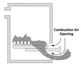
Flame Rollout
When the condition known as flame rollout occurs, flames rollout of the front of the combustion chamber when the burners are ignited (Figure 15).
Flame rollout may create a fire hazard or scorch appliance finishes, burn wire, or damage controls. The gas in the burners mixing tube may be ignited, producing flashback.
Remedies for flame rollout
Flame rollout is actually a variation of floating flames, with flames reaching for air outside the combustion chamber. Again, the basic cause is a lack of combustion air. This lack of air may be due to overfiring of the burners, poor draft, or blockages in flue passages. Apply many of the same corrections for these problems listed for floating flames.
Some appliances use step-type controls to achieve what as known as a soft start. These controls limit the initial gas flow to the burner by starting the appliance on low-fire to establish a draft in the appliance before the full flow rate or high fire is allowed. Check the operation of this control and replace it if it is faulty.
Use caution when opening access/service panels on appliances where rollout/floating flames are suspected. The flames can extend several feet and may cause burns to your face and/or hands.
Yellow Tipping
If not enough primary air is supplied to a Bunsen flame, yellow tips appear. Yellow tipped flames indicate incomplete combustion in appliances. This condition is aggravated if the flames impinge on cool surfaces such as the heat exchanger. Yellow flames which produce soot (carbon) on the heat exchanger can have an insulating effect on heat transfer; a 1/32 of an inch build up of soot or scale on the combustion side of the heat exchanger could result in efficiency losses exceeding 16%. Sooting presents a serious problem if it collects to restrict flue passages. Plugged flue passages impede venting of combustion products and therefore, reduces the amount of air that can be drawn into the combustion chamber. If the volume of combustion air is decreased, incomplete combustion can occur.
Do not confuse yellow tips with red or orange streaks which sometimes appear in flames. These colour streaks are usually due to dirt and dust in the primary air supply and can usually be eliminated by cleaning the burner and or air supply grill to the appliance. By using tinted glasses, such as brazing or cutting goggles, will eliminate the orange streaks from view, leaving true yellow tips still visible.
Remedies for yellow tipping
Yellow tipping is caused by a lack of primary air. This condition may be due simply to an incorrect setting of the primary air shutter. If this is the case, slowly open the primary air shutters to get rid of the yellow tips. Make sure that the increase in primary air does not cause flame lifting or flashback.
Lint and dust may restrict primary air openings, or collect inside the burner tube, or on the inside of the burner head to reduce primary air, causing yellow tipping. If so, clean and readjust the burner. A burner orifice that is out of alignment, drilled improperly or is dirty will reduce primary air injection. Check the orifice. Clean it, realign it, or replace it if necessary.
Fluctuating Flames
A fluctuating gas pressure at the burner orifice can cause the length of burner flames to fluctuate over a period of time without adjusting the burner. Fluctuating flames usually do not create any immediate problems, such as incomplete combustion, unless flames impinge on cool surfaces. This condition should be corrected however since it warns of possible future problems and appliance efficiency losses.
Remedies for fluctuating flames
Unsteady gas pressures cause flames to fluctuate. Usually this condition indicates a supply problem such as; faulty or oversized hunting regulator, or undersized gas piping causing other appliances to affect the gas line pressure.
If burner flames shorten without changes in gas pressure or primary air adjustment. Check the burner orifice for blockages by dust or dirt from the supply piping. Small pilot orifices are quite prone to blockages. Occasionally, too much lubricant in pilot valves restricts gas flow to the pilot burner. Remove any excess lubrication.
Gas Odour at Primary Air Openings
Under normal burner operation, a negative pressure (vacuum) should exist inside the primary air openings of a burner, drawing in air. If all gas fed to the burner by the orifice does not flow to the burner head, some gas may spill from the primary air openings. If this condition is found, check the burner for restrictions, and check that the orifice is not out of alignment.
 Now complete Self-Test 2 and check your answers.
Self-Test 2
Self-Test 2
- A luminous flame burner does not premix gas and air before ignition.
- True
- False
- A Bunsen burner produces a large glowing yellow flame.
- True
- False
- A Bunsen burner premixes the air with the gas before it is ignited.
- True
- False
- Which type of Bunsen flame has a yellowish color due to the presence of unburned carbon or hydrocarbons?
- Neutral flame
- Reducing flame
- Oxidizing flame
- Luminous flame
- Which type of Bunsen flame has a hissing shortened flame?
- Neutral flame
- Reducing flame
- Oxidizing flame
- Luminous flame
- The flow velocity is highest at the centerline of the burner port opening.
- True
- False
- Match the names of the burner parts to their lettered locations.
- Venturi
- Mixing Tube
- Burner Ports
- Orifice
- Burner Head
- Primary air openings
- What part of the burner increases the gas velocity and creates a negative pressure, used to suck in the combustion air?
- Orifice
- Venturi
- Burner port
- Mixing Tube
- The manifold pressure required for an atmospheric burner operating on propane gas is typically 2.5 times higher than that required for natural gas, in order to draw in the higher ratio of primary air required.
- True
- False
- One of the two pilot burner categories describes their ability to premix primary air. What does the other category describe?
- Orifice type
- Burner shape
- Ignition sequence
- Thermocouple types
- If flashback is occurring in an atmospheric burner, which of the following actions may be required?
- Clean the burner and increase the primary air
- Clean the burner and decrease the gas pressure
- Decrease the primary air and/or increase the gas pressure
- Increase the primary air and/or decrease the gas pressure
- How can flame lift-off be corrected?
- Decrease the primary air
- Add more secondary air
- Increase the pipe size to appliance
- Turning the regulator adjusting screw clockwise
- What usually causes a noisy, lifting, blowing pilot flame?
- High gas pressure
- A lack of secondary air
- Too large of a pilot orifice
- A partially blocked pilot orifice
- Which of the following conditions would cause a floating flame?
- Low gas pressure
- A blocked vent
- Too much primary air
- An underfired appliance
- What could be the problem with a furnace if a flame is waving or rolling out when the air circulation fan comes on?
- Too much primary air
- A cracked heat exchanger
- Partially blocked flue outlet
- An over-pressurized manifold
Check your answers using the Self-Test Answer Keys in Appendix 1.
Media Attributions
- Figure 1 “Luminous flame” by Camosun College is licensed under a CC BY 4.0 licence.
- Figure 2 “Bunsen Burner” by Camosun College is licensed under a CC BY 4.0 licence.
- Figure 3 “Burner port flow velocity” by Camosun College is licensed under a CC BY 4.0 licence.
- Figure 4 “Atmospheric burner parts” by Camosun College is licensed under a CC BY 4.0 licence.
- Figure 5 “Primary air control devices” by Camosun College is licensed under a CC BY 4.0 licence.
- Figure 6 “Four Inshot mono-port burners” by Camosun College is licensed under a CC BY 4.0 licence.
- Figure 7 “Upshot mono-port burner” by Camosun College is licensed under a CC BY 4.0 licence.
- Figure 8 “Multiport upshot burners” by Camosun College is licensed under a CC BY 4.0 licence.
- Figure 9 “Burner bed” by Camosun College is licensed under a CC BY 4.0 licence.
- Figure 10 “Aerated pilot with thermocouple” by Camosun College is licensed under a CC BY 4.0 licence.
- Figure 11 “Aerated incinerating pilot” by Camosun College is licensed under a CC BY 4.0 licence.
- Figure 12 “Non-aerated target pilot” by Camosun College is licensed under a CC BY 4.0 licence.
- Figure 13 “Floating flame” by Camosun College is licensed under a CC BY 4.0 licence.
- Figure 14 “Waving flame” by Camosun College is licensed under a CC BY 4.0 licence.
- Figure 15 “Flame rollout” by Camosun College is licensed under a CC BY 4.0 licence.
- “Burner parts – matching” in Self-Test 2 by Camosun College is licensed under a CC BY 4.0 licence.
