Learning Task 1
Understanding Gas Sizing Tables
The gas piping system must be sized using good engineering practice which accounts for all of the flow factors. This can be done by way of gas flow formulas or more easily by using the capacity tables supplied in Annex A and B of the 149.1 Gas Code.
Flow Factors
As was previously studied, the factors that affect the gas rate of flow in a piping system are:
- Relative density of the gas
- Length of pipe
- Pressure drop
- Diameter of pipe
The first two factors will be determined by the installation itself. Additionally, the pressure drop available will also have limitations based on good engineering practice.
Even though the greater the pressure difference between two points in a pipe line will increase the volume of gas being delivered, there are limitations. For example, there will still need to be adequate pressure left at the end of the pipeline to operate the appliance controls and burners. Additionally, if the piping system is operated at to great of a pressure drop the system will be very noisy as the flowing gas could reach sonic velocity.
For these reasons the Natural Gas and Propane Installation Code book specifies the maximum allowable pressure drop in a system, based on the system supply pressure.
Gas piping systems with supply pressures:
- less than 7″ w.c. (1.75 kPa) must be designed so the pressure drop does not exceed 0.5″ w.c. (125 Pa).
- 7″ w.c. to 14″ w.c. (1.75 kPa to 3.5 kPa) must be designed so that the pressure drop does not exceed 1″ w.c. (250 Pa).
- the pressure drop for a 2 Psig (14 kPa) system operating on natural gas can be either 1.5 Psig (10 kPa) or 1 Psig (7 kPa) depending on what pressure is required at the end of the operating system. The pressure drop for a 2 Psig (14 kPa) system operating on propane must not exceed 1 Psig (7 kPa).
- 5 Psig (34 kPa) systems must be designed so that the pressure drop does not exceed 2.5 Psig (17 kPa).
- 10 Psig (70 kPa) systems must be designed so that the pressure drop does not exceed 5 Psig (34 kPa).
- 20 Psig (140 kPa) systems must be designed so that the pressure drop does not exceed 10 Psig (70 kPa).
Therefore, the pipe size becomes the flow factor that must be properly selected by the installer.
Selecting the Correct Capacity Table
Selecting the proper table may seem like a simple task but when you consider there are 96 different tables to choose from it is easy to see why the majority of mistakes that are made in sizing are attributed to simply using the incorrect table.
Each table is based on the following sequence of pipe system criteria:
- Type of gas
- Type of Pipe
- System supply pressure
- Pressure drop
Review the description at the top of the tables as you read through the following criteria explanations. The required information is presented in an order that will enable you to selectively pinpoint the correct table.
Type of Gas
The gas code includes tables for sizing both natural gas and propane gas systems. The natural gas tables are included in Annex A and the propane tables are in Annex B. If an alternate gas is being used Table A.15 has multipliers that can be used to convert the natural gas table values for the alternate gas.
Type of Pipe
The first half of the tables in each Annex are for use with carbon steel pipe systems. Tables A.1 to A.7 in Annex A for natural gas or Tables B.1 to B.5 in Annex B for propane. These tables may also be used for a plastic piping system but you will need to be aware of the inside diameter of the type of plastic being used as it may be less than inside diameter (ID) of schedule 40 steel pipe, which was used to calculate the capacities for these tables. Although plastic pipe has smoother flow characteristics that carbon steel pipe, a reduced plastic pipe ID size may cause lower flow capacities. For reference Table A.17 supplies the ID of some of the different plastic pipes based on their Standard Dimeson Ratio (SDR).
The second half of the tables in each Annex are for used with copper tube systems. Tables A.8 to A.14 in Annex A for natural gas or Tables B.6 to B.10 in Annex B for propane. These tables are based on Type K tubing as it has a smaller inside diameter than Types G and L.
Manufacture supplied sizing tables must be used when sizing corrugated stainless steel tubing (CSST). These are typically laid out and used in the same manner as the B149.1 Gas Coed tables.
System Supply Pressure
The system supply pressure is also identified at the top of each table. Notice that the previously identified table criteria groupings start with the lower system supply pressure, then increased with each subsequent table. There is an Imperial and a metric version of each table within this identified system supply pressure. For example, Table A.1(a) is for gas supply pressures less than 7 in w.c. or the metric equivalent Table A.1 (b) is for gas supply pressures less than 1.75 kPa.
Pressure Drop
Although pressure drop is the most important factor affecting the flow of gas in a piping system it is listed last in our table selection process, only because the allowable pressure drop has already been determined for us by the calculations made within the table. By staying within the values shown in these tables we will ensure that the pressure drop listed at the top of the tables is not exceeded. For most of the tables you will not need to select the pressure drop, this will be determined by the selection of the appropriate system supply pressure table. The only exception is for 2 psig (14 kPa) natural gas systems, were there is a choice between using a pressure drop pf 1 psig (7 kPa) or 1.5 psig (10 kPa). In this case you will need to consider the minimum required inlet pressure at the end of the 2 psig system that will be necessary for the line pressure regulator to function correctly. If unsure it is always best to size the system based on a 1 psig (7 kPA) pressure drop, this will ensure the most left-over energy at the end of the 2 psig system.
Using the Capacity Tables
To use the tables there is important information that must be gathered. This information is best placed on a system sketch or drawing for reference. The creation of the system drawing will be covered in competency E-4 Design a Building Fuel Gas Distribution System. For consistency the drawing will be supplied to you in this competency.
From the design drawing you will need to know:
- Load on each section of pipe
- Length of pipe or tube
Piping loads
This term expresses the volume of fuel that must pass through a pipe each hour. This volume is determined by all of the appliance maximum inputs that are connected to that pipe. Each section of pipe has its own piping load. The capacity table pipe loads are expressed in thousands of Btuh (MBH) or kW, if the exact required load demand is not shown in the table the next larger table value will be used to ensure the pipe has ample flow capacity.
Pipe Length
The longer the length of run of the piping or tubing, the greater the pressure drop that will occur for a given flow rate. Therefore, in order to ensure a minimum pressure drop, pipe and tube sizes will need to increase for systems with longer runs. In order to simplify the sizing process, and ensure that the maximum allowable pressure drop is not exceeded to any of the appliances, the distance from the system supply meter or regulator to the furthest appliance is used for the entire pipe sizing procedure. This distance represents the worst-case scenario and will be known as the Longest Measured Run (LMR) of the piping system. Each fitting on a pipe system adds resistance to the gas flow, notice that some of the tables will include in their description “including fittings” and others will not. If the pipe sizing table includes fittings, a 20% allowance has been included in the table length. This allowance is usually more than enough for a normal piping system. For the higher pressure tables that do not include a fitting allowance, the fittings will need to be individually accounted for when computing the longest run, this will be explained in detail later.
Reading a Capacity Table
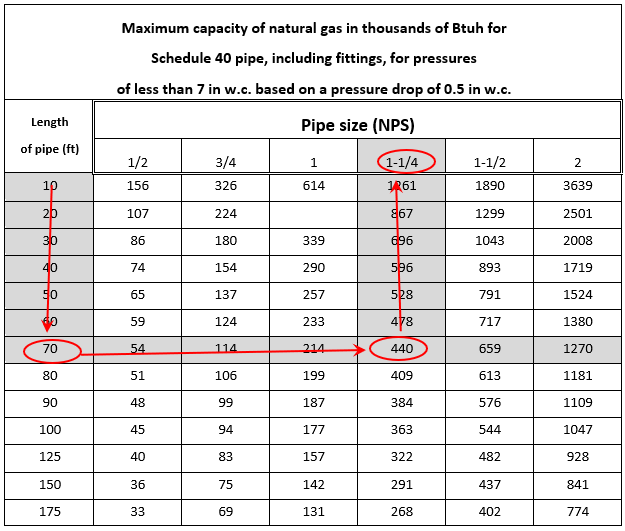
Assuming the required table for the system was Table A.1 (A) Imperial, we will use similar table shown in Figure 1 as a guide, for a single appliance system that has:
- Longest measure run (LMR) of 65 ft.
- Appliance maximum rated input of 300,000 Btuh
Use the following procedure when using the tables:
- The rated inputs will first need to be converted to MBH for the purpose of the tables. 300,000 Btuh/1000 = 300 MBH
- Look down the length of pipe column for a value exactly the same or larger than the longest measure run, this row will be referred to as the code zone (CZ). If there was more than one appliance on this pressure system, this would be the only row that would be used in the entire sizing procedure for that whole system. LMR of 65 ft. = CZ of 70 ft.
- Move across the code zone until an equal of greater value then the pipe load being sized is located. For pipe load of 300 MBH stop at 440 MBH
- The required pipe size is shown at the top of the column. In this case 1 ¼″ NPS iron pipe size is required.
 Now complete Self-Test 1 and check your answers.
Self-Test 1
Self-Test 1
- The greater the pressure drop through a piping system the more volume of gas being delivered.
- True
- False
- The gas pipe sizing tables in the B149.1 code book do not limit the amount of pressure drop in the piping system.
- True
- False
- The greater the pressure drop through a piping system the more pressure that is left at the end of the pipeline.
- True
- False
- If the piping system is operated at to great of a pressure drop, the system will be very noisy as the flowing gas could reach sonic velocity.
- True
- False
- Using the alternate gas Table A.15 for what is the multiplier for Butane gas (SG 2.00) that can be used to convert the natural gas tables?
- 1.31
- 1.00
- 0.680
- 0.547
- Which table supplies the inside diameters of some of the different plastic pipes based on their Standard Dimeson Ratio (SDR).
- Table A.15
- Table A.16 (a)
- Table A.16 (b)
- Table A.17
- The copper tube tables are based on Type K tubing as it has a larger inside diameter than Types G and L.
- True
- False
- For the list identify in order pipe system criteria in the best order that will ensure the proper table is selected.
- System supply pressure
- Pressure drop
- Type of gas
- Type of pipe
- The B149.1 sizing table can be used when sizing corrugated stainless steel tubing (CSST).
- True
- False
- Within the identified table criteria groupings the tables start with the lower system supply pressure, then increased with each subsequent table.
- True
- False
- If the exact required load demand is not shown in the table the next larger table value will be used to ensure the pipe has ample flow capacity.
- True
- False
- To ensure that maximum allowable pressure drop is not exceeded to any of the appliances, the distance from the system supply meter or regulator to the furthest appliance is used for the entire pipe sizing procedure.
- True
- False
- When using the imperial sizing tables the rated inputs will first need to be converted to MBH.
- True
- False
Check your answers using the Self-Test Answer Keys in Appendix 1.
