Learning Task 1
Describe the Natural Gas Supply and Distribution System
Natural gas either in a gaseous or liquid state can be transported between facilities or to consumers by ships/vessels, special trucks, and pipelines.
Pipelines are an efficient and safe means of transporting natural gas. Some of the advantages of using a pipeline to transport gas are:
- Continuous delivering of gas to consumers without disruption. The delivery is not affected by most environmental factors.
- Pipelines can be routed to take short cuts to its destination thereby reducing the time of transportation compared to other means of transportation.
- The large volume of gas that is transported
According to the Fraser Institute’s 2015 study, pipeline transportation is the safest and most reliable means of transporting gas.
Bringing Fuel Gas to the Consumer
With so many varieties of geological formations, Canada yields many types of natural gas. Exploration studies and seismographic surveys indicate likely sources of oil and natural gas in a particular area.
Once a productive well has been established, gas processing plants separate the oil and gas into different productive components. Transmission companies move both the natural gas and liquefied petroleum (LP) gases to markets thousands of miles from the wellhead.
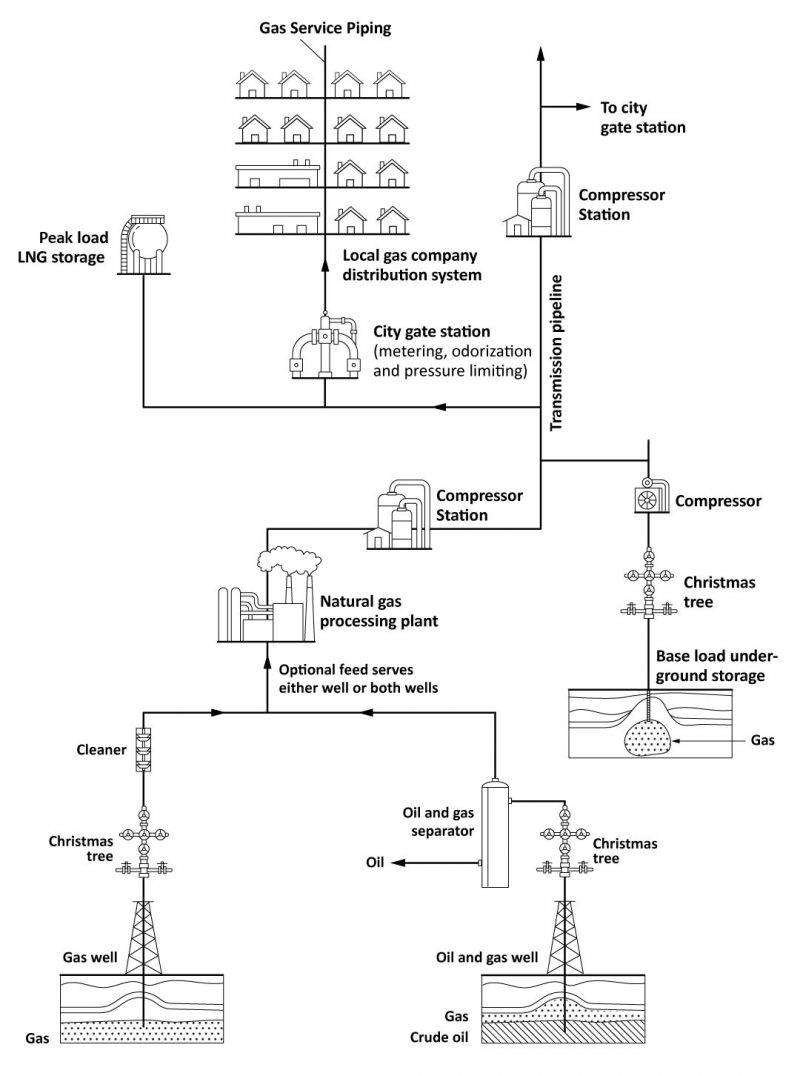
The process of gas transmission, storage and distribution, from drill well head to consumers, is shown in Figure 1.
Drilling
Drill rigs are units composed of a complex arrangement of machines and instruments which bore through the porous sedimentary rocks to find a pocket containing trapped crude oil or natural gas. As the borehole is being drilled, the hole is sheathed in a steel casing at various depth intervals to support the well from collapsing and create a controlled return path for the pumped drilling fluid and removed material. The upper first depth interval casing string is cemented into place, then each consecutive depth interval is drilled to a smaller size and the subsequent casing slips inside the previous one, and they are all run to the surface (well head) were they are supported. Once the drilling rig has completed it is dismantled and relocated.
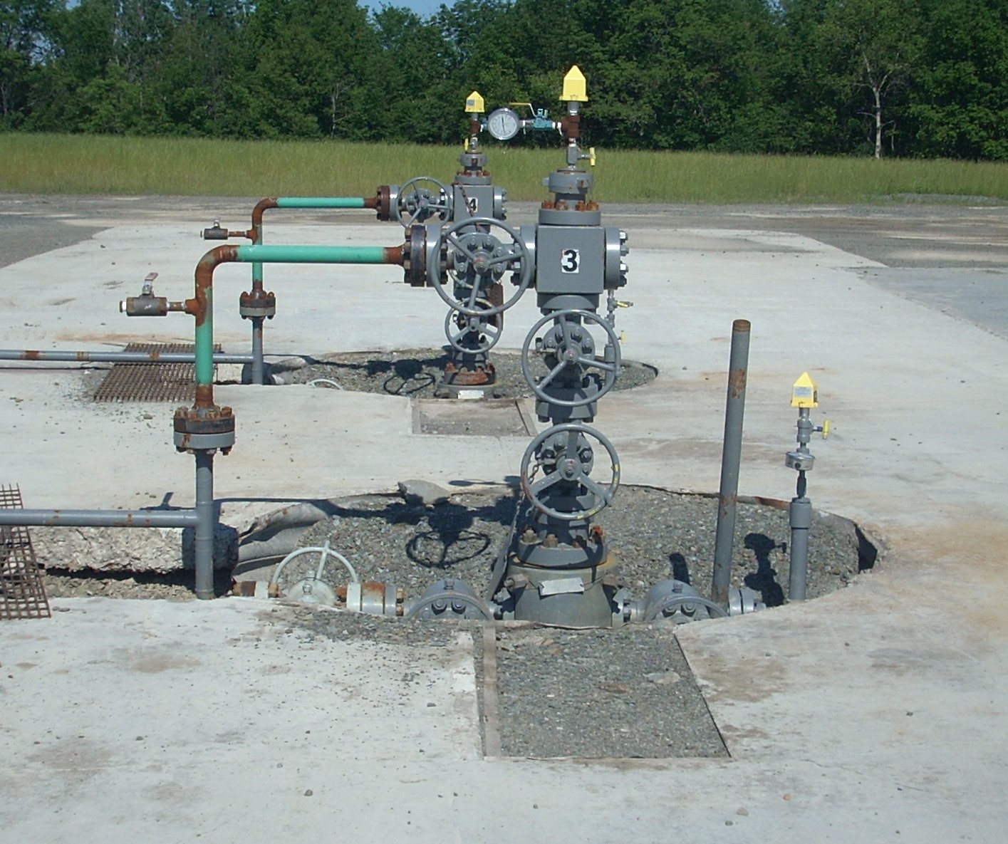
If it has been established that the well will produce sufficient oil or gas, then production tubing is run through the casing to transport the oil and gas to the surface. The production tubing is connected at the surface to an assortment of valves, pressure gauges, and flow line connections (Figure 2), often called a “Christmas tree.”
Processing
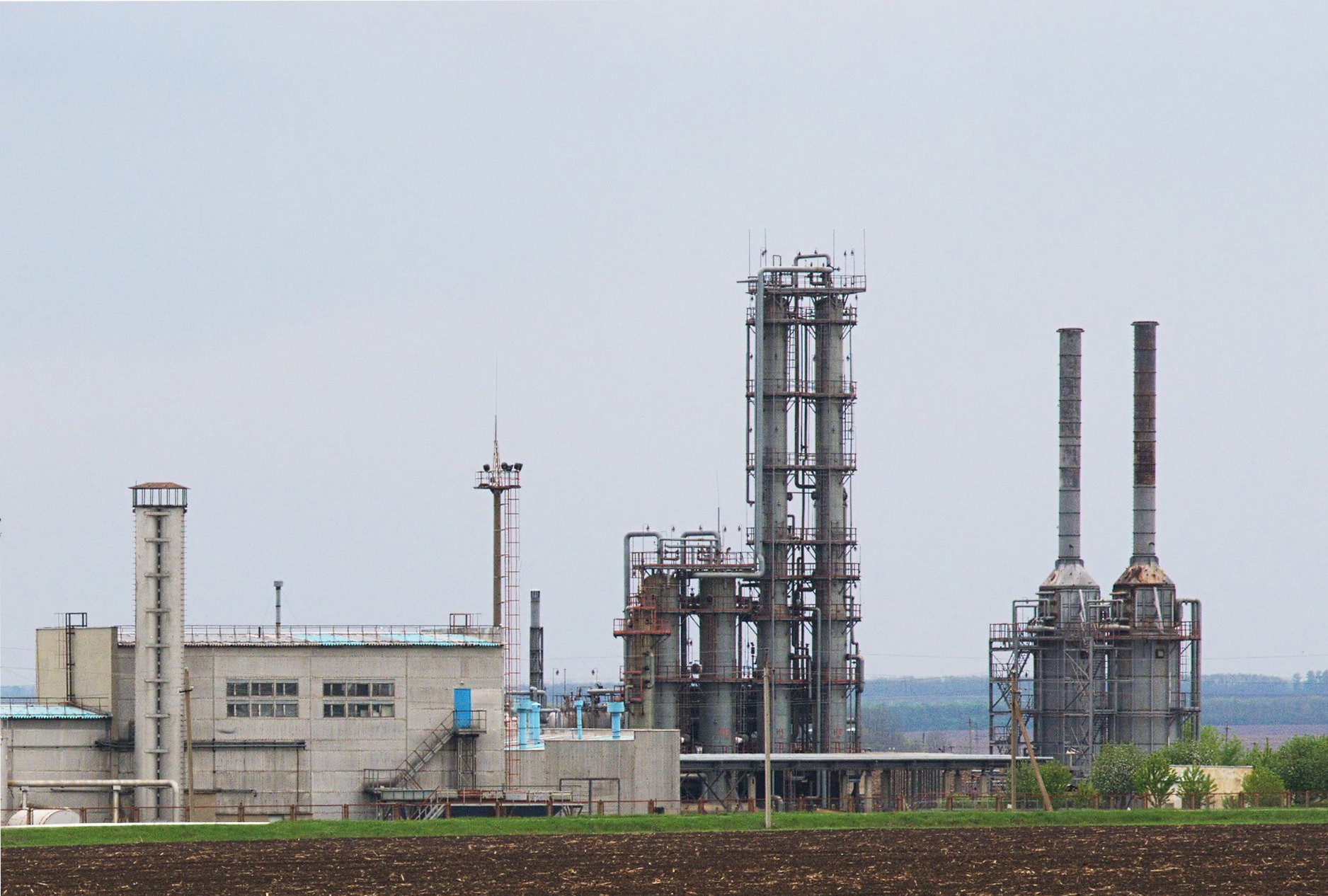
Gas processing plants operate near the well fields and separate the components of natural gas that are used in different areas of the petrochemical industry (Figure 3). It is noteworthy that many processing plants obtain more revenue from the sale of gas by-products than from the sale of gas itself. Sulphur is one example of a major by-product.
Transportation
Because of their different natures, natural gas and LP-gases are transported to consumers in different ways.
Natural gas
Large pipeline transmission companies gather the gas from the plants and channel the fuel to local and distant markets. The natural gas is compressed from 5500 – 8000 kPa (800 to 1,200 psi) so that it can be pushed though the transmission pipelines at speeds of 11–32 kilometers per hour.
As natural gas moves through a pipeline, distance, friction, and elevation differences slow the movement of the gas, and reduce its pressure. To ensure that gas continues to flow optimally the pressure must be periodically boosted, so additional compressor stations are placed, typically 80 – 100 kilometers apart, along the pipeline.
The transmission companies take care of maintenance of pipelines which includes checking cathodic protection levels for the proper range, and surveillance for construction, land erosion, or leaks.
LP-gas
LP-gases are not transported in their gaseous state, since they were condensed into the liquid state upon extraction from natural gas or petroleum oil. After they leave the refinery, they are stored in a liquid state under pressure.
Distribution
When the transmission company has delivered it, and before the local utility can use the gas, it must have its pressure reduced. To do this, the gas passes through a regulating station, called a city gate or town gate. Distribution city gate branches may be installed at points along the transmission line.
The city gate station controls metering, pressure limiting, and odourization of the gas before it is finally distributed by the utility company to the individual consumers. Since natural gas is colourless and odourless specific chemicals, called mercaptan, are added, to give natural gas a distinct odor before it is distributed to the highly populated areas. That rotten egg odour is used as a safety measure to ensure that natural gas leaks do not go undetected. The transmission pipeline pressures are reduced to below 690 kPA (100 psi) at the gate stations then transported to the consumers through the distribution mains.
Storage
The natural gas storage infrastructure can be utilized to accommodate sudden rises or falls in demand. Storage acts as a buffer between transportation and distribution, to ensure adequate supplies of natural gas are in place for seasonal demand shifts (base load), and unexpected demand surges (peak load).
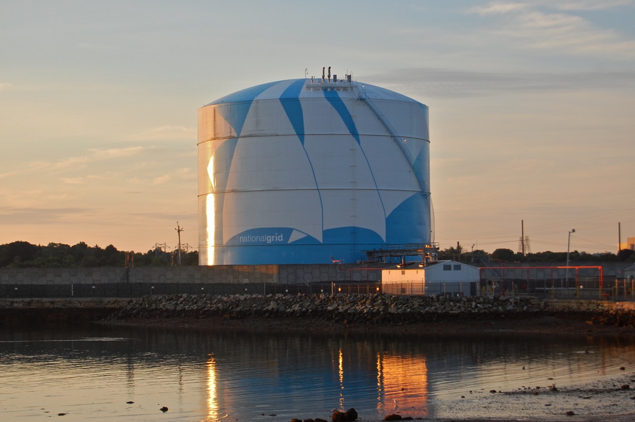
Base load gas is usually stored underground, in large storage reservoirs. There are three main types of underground storage: depleted gas reservoirs, aquifers, and salt caverns. In addition to underground storage, natural gas can be stored as liquefied natural gas (LNG) in large insulated above-ground tanks (Figure 4) for peak load periods. As a liquid at −161 °C (−258 °F), it occupies about 600 times less space than gas stored underground. The LNG storage facilities are generally located close to market, giving them the ability to provide high deliverability at very short notice, by releasing and returning the liquid to its gaseous state when it is needed.
The release of gas from the liquid storage is also used to maintain the remaining stored liquid at low temperature, this is known as auto-refrigeration.
LP-gases in refineries are also stored in above-ground storage tanks similar to natural gas storage facilities. They range in capacity from 2 kg tanks to tanks which hold thousands of liters.
Service Piping
The gas utility installs and maintains the gas service, which includes the service line, service riser, service stop (valve), service regulator, and meter (Figure 5).
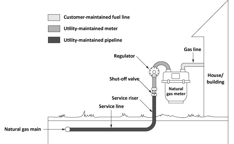
The Natural Gas and Propane Installation Code specifies the maximum gas pressures allowed inside different classes of buildings. The service regulator will need to reduce the utility distribution pressure accordingly, for example a single-family dwellings is limited to a maximum of 14 kPa (2 psig), whereas pressures in industrial and commercial applications range from 35 to 140 kPa (5 to 20 psig).
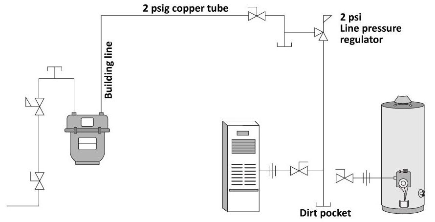
Consumer Gas Piping System
The consumer gas piping system conveys the fuel gas from the point of supply to the gas burning appliances. It may be black iron pipe, CSST, copper tubing or polyethylene (PE) plastic (underground only). The point of supply for natural gas is usually a gas utility companies’ meter and, for propane, a propane storage tank. The gas fitter is responsible for designing a piping system, capable of supplying the required volume of gas to each gas-fired appliance, following good piping practices and the requirements of the B149.1 National Gas Code. Figure 6 shows the typical parts of a consumer fuel gas piping system.
 Now complete E-1 LT1 Self-Test and check your answers.
Self-Test 1
Self-Test 1
- What is the safest and most reliable method of transporting natural gas?
- Trucking
- Railway
- Pipeline
- Aircraft
- Transmission lines are the pipes that move the gas from the city gate station to the customers.
- True
- False
- What is the maximum pressure of natural gas in city distribution mains?
- 35 kPa
- 140 kPa
- 680 kPa
- 8000 kPa
- The release of gas from the liquid storage will reduce the temperature of the remain liquid.
- True
- False
- What is the maximum Natural gas supply pressure to a single-family dwelling?
- 14 kPa
- 35 kPa
- 140 kPa
- 450 kPa
Check your answers using the Self-Test Answer Keys in Appendix 1.
Media Attributions
- Figure 1 “Gas transmission from drill site to utility company” by Camosun College is licensed under a CC BY 4.0 licence.
- Figure 2 “Gas wells” by Gerry Dincher is licensed under a CC BY-SA 2.0 licence.
- Figure 3 “Solohiv natural gas plant” by ReAl is licensed under a CC BY-SA 3.0 licence.
- Figure 4 “National Grid LNG Tank” by Fletcher6 is licensed under a CC BY-SA 3.0 licence.
- Figure 5 “Consumer gas service” by Camosun College is licensed under a CC BY 4.0 licence.
- Figure 6 “Building gas piping system” by Camosun College is licensed under a CC BY 4.0 licence.
- “Check” by Kimmi Studio is licensed under a CC BY 4.0 licence.

.jpg)