Learning Task 3
Sizing Gas Piping Systems Over 2 psig
High pressure gas is any gas pressure over 1/2 psig. Although the two psig gas piping systems discussed in LT3 are classified as high pressure, the pipe sizing tables include fittings. This Learning Task will only discuss systems used in industrial and commercial applications, operating at 5 to 20 psig, were the pipe capacity tables do not have an allowance for fittings built into them.
Although not technically correct, the two different sizing procedures are often referred to as:
- Low Pressure Sizing; when fittings are included in tables
- High Pressure Sizing; when fittings are not included in
For the high pressure sizing procedure it will be necessary to complete a separate fitting allowance calculation.
Calculating Fitting Allowances
If a pipe sizing table does not include an allowance for fittings, the resistance through the fittings must be added to the measured length. The resistance through a fitting is expressed as the equivalent resistance through a specific length of straight pipe. In other words, each pipe fitting is equal, in resistance, to an equivalent length of straight pipe. The equivalent length values are listed in Tables A.16 and B.11 of the Natural Gas and Propane Installation Code.
Fitting Equivalent Length Tables
Both table A.16 and B.11 are identical and either can be used for natural gas or propane system sizing. Each one has an imperial and metric version it is very important to not get these mixed up. As this is a common error we recommend highlighting the words imperial and metric on all tables.
When looking at the table we notice the following columns and information:
- The first column on the far left identifies the fitting sizes by there nominal imperial pipe size for both the metric and imperial tables you will select a row in this column that matches your fitting size
- The second column shows the actual inside diameter of the different nominal sizes. This column is for reference only and will not be used. The equivalent lengths shown in the tables have been computed on the basis that the inside diameter corresponds to that of Schedule 40 (standard-weight) steel pipe, which is close enough for most purposes.
- The third column is used for threaded 45 degree elbows. For example a ½″ threaded 45 degree elbow would create resistance to gas flow equivalent to that of 0.73 feet (0.22 metres) of ½″ pipe.
- The fourth column is for threaded 90 degree elbows
- The fifth column is for threaded tees
- The sixth column is for valves. Although the table shows a Plug style valve, this column will be used for all quarter turn valves. Notice the values in this column are the same as those in the threaded 90 degree elbow column.
- The Globe, Angle and Swing check columns will not be used for gas systems they would only be applicable to the Liquid side of an LP system.
- The last three columns are used on a welded piping systems. The welded bend values are for standard radius manufactured 90 degree butt weld fittings. There are two welded tee columns depending on whether the tees are manufacture forged tees or fabricated mitred tees. Socket weld fittings which have more resistance are often used for welded pipe sizes under 2″. For socket weld 90 degree fittings use the threaded 90 degree fitting column. For socket weld tees use the mitred tee column although the threaded tee column will also work.
It is important to remember that when we are performing the fitting equivalent length tabulation only the fittings that are on the LMR path will be listed in the material list, as the purpose of the tabulation will be to add the equivaled length of fittings to the LMR to get the Longest Equivalent Run (LER).
Some addition points to keep in mind when calculating the fitting equivalent length are:
- Do not include fittings which do not change the direction of flow (pipe couplings, unions, reducing couplings), other than valves.
- Only tees which change the direction of flow 90 degrees are included in the equivalent length of pipe, do not include tees were the measure run that is being calculated flows through the run of the tee.
- Reducing tees that change flow direction are calculated by using the largest inlet size of the tee.
Sizing Procedure
As you saw in order to use the fitting equivalent length table you will first need to know the pipe sizes. Since pipe sizing tables for system pressures of 5 Psig (34 kPa) and higher do not include fittings, an estimate for fittings will be added to the longest measured run in order to select an estimated code zone for the initial sizing. These initial pipe sizes can then be used to calculate the total equivalent length of the fittings on the LMR. The calculated equivalent length of fittings will then be added to the actual measured length of the run to see whether or not the estimate code zone was correct.
The high pressure sizing procedure is similar to low pressure, except for steps seven and nine:
- Identify the gas (natural gas, propane, etc.).
- Identify the piping material (carbon steel pipe, copper tubing, or other).
- Identify the pressure system and the allowable pressure drop.
- Select the correct pipe sizing table.
- Calculate the gas load in Btu/h (or kW) on each section of pipe and list each load.
- Calculate the longest measured run in the system.
- Estimate the appropriate code zone.
- Size each pipe in the system from the estimated code zone.
- Prove the code zone
Step seven - At this point, you do not know the size of the fittings, so you must include an allowance for a reasonable number of fittings that is added to the measured run to select a code zone for initial sizing. This initial estimate can be done by simply adding 20% to the measured run. At this point it is not imperative that you estimate is correct as that will be checked in step number nine. When you become more familiar with the process you will start recognize situations were a different percentage would be better suited, due to runs with excessive or very few fittings.
Step eight - sizes the pipe based on that estimated code zone.
Step nine - is a check to see whether you chose the correct code zone. This is very important. Since you have guessed at the code zone, if the fitting estimate was incorrect and the wrong code zone was used the pipe sizes may not be correct. You do this check by comparing the LER to the code zones that were available to use in the selected table. If the wrong estimated code zone was used then the pipe sizes must be rechecked in the appropriate code zone to see if any of the sizes will change.
Examples 1 -5 psig (34 kPa)
Refer to Figure 1 for an example of the sizing of a 5 psig system. Go through each step to size each pipe in the system.
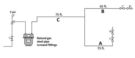
- Identify the type of gas; Natural gas
- Identify the type of pipe; Carbon steel pipe
- Identify the system operating pressure; The gas pressure being delivered through the gas meter is 5 psig.
- Select the pipe sizing table; From the information gathered in Steps 1, 2 and 3;, the appropriate table to be used is Table A.5 (Imperial). By using Table A.5, the pressure drop in the system should not exceed 2.5 psig.
- Calculate loads on each section of pipe in thousands of Btu’s per hour (MBH);
- Pipe “A” = 1,000 MBH
- Pipe “B” = 750 MBH
- Pipe “C” = Pipe “A” + Pipe “B” = 1,750 MBH
- Calculate the longest measured run of the system; LMR =145 feet to the end of Pipe A.
- Estimate the code zone, then from the table chose a code zone that is closest to your estimate;
- Multiply the longest measured run by 1.2 (adding 20% for fittings).
- 145 feet x 1.2 = 174 ft.
- If you refer to Table A.5 you can see, the code zone that is closest to our estimate is 175 feet, so we will choose that code zone for our initial sizing
- Size each pipe in the system using the same selected code zone;
- Pipe “A”: 1,000 MBH = 3/4″
- Pipe “B”: 750 MBH = 3/4″
- Pipe “C”: 1,750 MBH = 1″
- Prove the Code Zone: To proof the length of pipe runs, add the measured length of pipe with the fittings equivalent length of pipe to find the total equivalent length of the run. You must ensure that path that created the longest equivalent run is verified. This is typically the initial LMR plus its fitting equivalent length, but occasionally a shorter measure run may tun out to be longer in equivalent length due to, more or larger, fittings. For this reason, it may be necessary to proof additional runs beyond the initial LMR proof.
Proof Procedure:
- List all fittings on the run, starting with the longest measured run. Remember it is only the fittings that are on the run being proofed not all of the fittings on the system. A highlighter is very helpful for this step.
- Look up their equivalent lengths from Table A-3.
- Add the fittings equivalent length to the measured length to get the total equivalent length of the run.
- Once you have verified the Longest Equivalent Run (LER) compare it to the estimated code zone that was used to ensure it was the correct choice.
- If a more appropriate code zone is identified than you must resize the piping on the proper code zone.
- If any pipe sizes change then the system needs to be reproofed to verify that the new code zone was correct.
Meter to regulator serving appliance at Pipe A (LMR):
[latex]\begin{array}{ll} \text{3 - 1″ threaded 90° @ 2.62 feet} & = 7.86 \text{ feet} \\ \text{1 - 1″ threaded tee @ 5.24 feet} & = 5.24 \text{ feet} \\ \text{2 - ¾″ threaded 90° @ 2.06 feet} & = 4.12 \text{ feet} \\ \text{1 - ¾″ threaded valve @ 2.06 feet} & = \underline{2.06 \text{ feet}}\\ \text{Equivalent Fitting Length} & = 19.28 \text{ feet} \\ \text{Measured Length} & = \underline{145.00 \text{ feet}} \\ \text{Equivalent Length of Run (ELR)} & = 164.28 \text{ feet} \end{array}[/latex]
By looking at the drawing of this simple system it is pretty easy to tell that the run from pipes C to B will not be longer in equivalent length when you consider that pipes A and B are the same size and pipe B has less fittings.
On more complexed systems it is not as easy to determine this without performing a proof of any alternate runs that you suspect may be longer in equivalent length. Therefore for this example we have also performed a proof of the C to B run for the purpose of demonstrating the process of checking alternate runs.
Meter to regulator serving appliance at Pipe B (C-B):
[latex]\begin{array}{ll} \text{3 - 1″ threaded 90° @ 2.62 feet} & = 7.86 \text{ feet} \\ \text{1 - 1″ threaded tee @ 5.24 feet} & = 5.24 \text{ feet} \\ \text{1 - ¾″ threaded 90° @ 2.06 feet} & = 2.06 \text{ feet} \\ \text{1 - ¾″ threaded valve @ 2.06 feet} & = \underline{2.06 \text{ feet}}\\ \text{Equivalent Fitting Length} & = 17.22 \text{ feet} \\ \text{Measured Length C-B} & = \underline{140.00 \text{ feet}} \\ \text{Equivalent Length of Run (ELR)} & = 157.22 \text{ feet} \end{array}[/latex]
If both pipe A and pipe B’s equivalent length of runs are less than the selected code zone, the code zone is okay. In neither case does the ELR exceed the selected code zone of 175 ft. Therefore, the 175 ft code zone is okay and the pipe is sized correctly
If any ELR had exceeded the chosen code zone, it would indicate the chosen code zone is too short and the piping would have to be resized and re-proofed on the next longest code zone.
Additionally, there is the possibly that the fitting allowance guess was very excessive. In that case if our Longest Equivalent Run (LER) was quite a lot shorter that the selected code zone and in fact fell within the next smallest code zone on the table, then we should also resize and reproof on the next shortest code zone so that we don’t unnecessarily oversize the system.
 Now complete Self-Test 3 and check your answers.
Self-Test 3
Self-Test 3
- Size the drawing in Figure 2 and show all calculations.
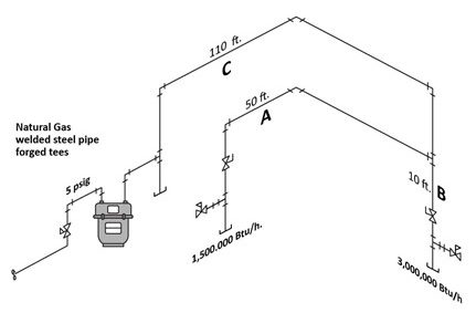
Figure 2 Type of Gas Piping Material System Pressure Table Used Table Allowable Pressure Drop Longest Measured Run (LMR) Code Zone (CZ) Proofed Longest (ELR) Pipe Letter Pipe Load Pipe Size A B C - Size the drawing in Figure 3 and show all calculations.
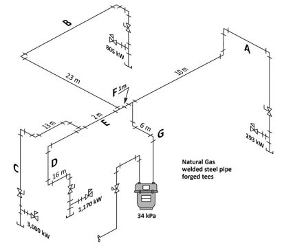
Figure 3 Type of Gas Piping Material System Pressure Table Used Table Allowable Pressure Drop Longest Measured Run (LMR) Code Zone (CZ) Proofed Longest (ELR) Pipe Letter Pipe Load Pipe Size A B C D E F G - Size the drawing in Figure 4 and show all calculations.
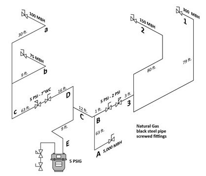
Figure 4 7″ WC Piping System:
Type of Gas Piping Material System Pressure - 7″ WS Table Used Table Allowable Pressure Drop Longest Measured Run (LMR) Code Zone (CZ) Pipe Letter Pipe Load Pipe Size A B C 2 PSG Piping System:
Type of Gas Piping Material System Pressure - 2 PSI Selected Pressure Drop - 1 PSI Table Used Longest Measured Run (LMR) Code Zone (CZ) Pipe Letter Pipe Load Pipe Size 1 2 2 5 PSG Piping System
Type of Gas Piping Material System Pressure - 5 PSI Table Used Table Allowable Pressure Drop Longest Measured Run (LMR) Code Zone (CZ) Proofed Longest (ELR) Pipe Letter Pipe Load Pipe Size A B C D E
Check your answers using the Self-Test Answer Keys in Appendix 1.
Media Attributions
- Figure 1 "Pipe sizing example for 5 psig system" by Camosun College is licensed under a CC BY 4.0 licence.
- Figure 2 by Camosun College is licensed under a CC BY 4.0 licence.
- Figure 3 by Camosun College is licensed under a CC BY 4.0 licence.
- Figure 4 by Camosun College is licensed under a CC BY 4.0 licence.
