Learning Task 2
Describe Flame Detectors
The control system of a gas appliance utilizes flame detection devises to ensure the pilot and or main burner are lit safely. Knowing how flame detectors work, where they are applied, and how they interact with other controls is important to understanding the overall flame safety circuit. Any pilot flame that is supervised by some form of primary safety control designed to sense its presence before prior to gas being admitted to the main burner is referred to as a Proved pilot. The following flame detectors are commonly used with pilot flame ignition systems:
- Thermocouple
- Thermopile
- Flame rod
Thermocouple
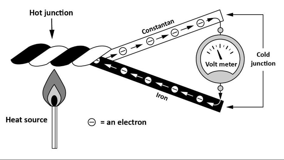
The thermocouple is made of two dissimilar metals joined together at one end called the hot junction. The opposite end, which is not joined together, is called the cold junction (Figure 1). It is important that only [latex]\dfrac{3}{8}[/latex] to [latex]\dfrac{1}{2}[/latex] in (10 mm to 13 mm) of the hot junction is heated by the pilot flame, as the greater the temperature difference between the hot and cold junctions, the greater the voltage generated. The thermocouple generates approximately 25 to 30 millivolts (mV), which is enough to power the electromagnet in a safety shut-off valve or safety switch.
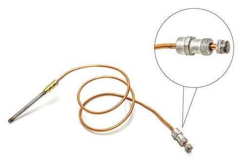
One of the ends of the cold junction is connected to the metallic outer sleeve of the thermocouple, while the other end of the cold junction is connected to an insulated wire inside the outer sleeve (Figure 2). The outer sleeve is typically made of constantan a nickel and copper-based which has a constant resistivity over a wide range of temperatures. The ends of the cold junction become the leads to the safety shut-off valve or switch. Commonly, thermocouples are 18, 24, and 36 in (0.5 m, 0.6 m and 0.9 m) long, but models are made as long as 60 in (1.5 m). When replacing a thermocouple, it is important to order one that matches.
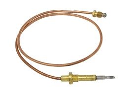
If the standing pilot flame were to be extinguished there is delay of up to 90 seconds, while the thermocouple cools, before the gas valve shuts off. Therefore, the gas code sets limitations on their uses depending on the gas input to the burner or the type of gas. For example, appliances with a specific gravity greater than air (such as propane), shall have a maximum flame response time of 20 seconds. These appliances will be equipped with fast response thermocouples (Figure 3). As many of these appliances, such as fireplaces, are convertible for either fuel this is the type of thermocouple that is installed.
Thermopile
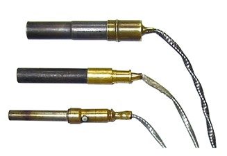
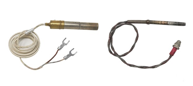
Thermopiles, also known as powerpiles or pilot generators, are similar to thermocouples and generate electricity from the heat of a pilot flame. Internally they consist of multiple thermocouples joined together in series to generate more voltage. Most thermopiles consist of 10 to 30 thermocouples connected in series, creating output ranges from 250 to 750 mV (Figure 4).
The higher voltage enables the thermopile to power an appliance’s combustion safety circuit and its control circuit, as long as the pilot is lit. If the pilot flame should go out, both circuits would be broken and shut off. Thermopiles are made in two designs, either two wire or coaxial (Figure 5). The coaxial style having a very similar connection as a thermocouple.
Flame Rod
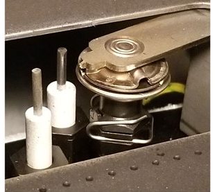
Many modern appliances have intermittent pilots which will have an electronic ignition system to light the pilot and a flame rod to detect the pilot flame. Flame rods are small diameter metal rods supported by an insulator, the tip-end of the rod projects into the flame(Figure 6).
For spark ignition systems the rod is typically made of “Kanthol” which is an alloy capable of operating in temperatures of up to 2,400 ºF (1,300 ºC). There is not always a separate flame rod sometimes the spark igniter and flame rod are combined and use the same rod to serve both purposes. For hot surface ignition system, the “Globar” which has a maximum operating temperature of 2,600 ºF (1425 ºC) can also double as the flame rod.
The operation of the flame rod is based on principle of flame ionization, whereby ions are formed during combustion process. This ionization process makes the flame a high resistance conductor of electricity. This phenomenon can be used to make a flame act like a switch and complete the flame sensing circuit by allowing a small amount of current to flow whenever the pilot flame is present (Figure 7).
The original systems developed that used this characteristic were susceptible to potential false flame indications through shorts circuits caused by carbon deposits that could conduct current. The flame rectification system was developed to recognize the difference between high resistance leakage to ground and an actual flame.
Flame Rectification System
When AC voltage is applied across the non-rectified flame conductive system shown in the previous Figure 7 the resulting flame current constantly changes during each half cycle of the AC supply. Consequently, the amount of current is the same in each direction.
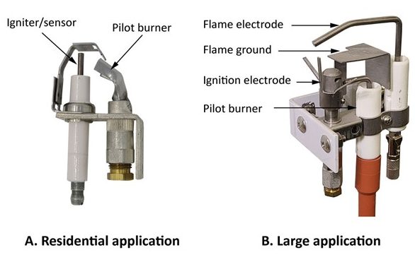
The flame rectification system also uses two electrodes, but with one important difference: the ground electrode is much larger than the flame electrode. Usually the ground electrode will be the burner head. In some cases, additional metal rods or plates must be added to the burner to increase the grounding surface area, as it must be at least 4 times larger (usually up to 10 times larger) than the flame rod or flame electrode. (Figure 8).
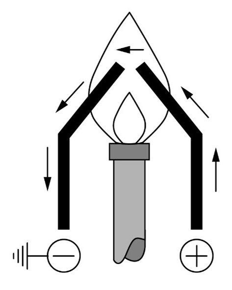
For a rectified system, when an AC supply voltage is placed across the two electrodes during the first half of the AC cycle, the flame rod is positive and the grounding area is negative (Figure 9 A). The positively charged ions collect on the negative charged grounding area. Since the grounding area is very large, it holds many ions. The positively charged ions pull a high stream of electrons into the flame, more than if the grounding area was the same size as the flame rod. This results in a high current flowing from the grounding area to the flame rod during the first half cycle of the AC supply voltage (Figure 9 C).
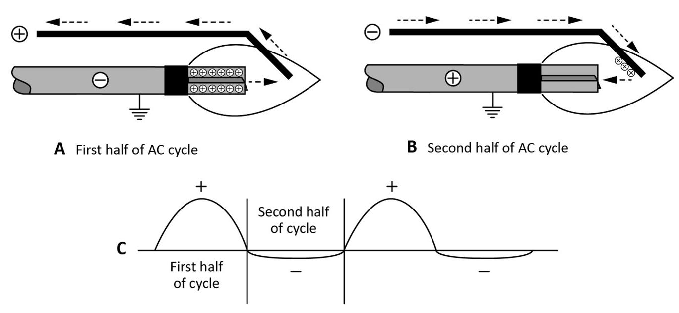
During the second half cycle, the reverse process takes place (Figure9 B). However, the capacity of the flame rod to hold ions is less than the grounding area and the resulting flame current is smaller (Figure 9C).
Since the current in one direction is so much larger than the current in the other direction, the resultant current is, effectively, a pulsating direct current (Figure 9C). The flame signal should be steady when measured with a DC microammeter (μA).
The advantage of a rectified system over a conductivity system is that the rectified system can detect a high resistance leak. Sometimes a short circuit occurs between the flame rod and ground; carbon may build up between the rods or the insulating ceramics may crack and allow moisture to provide a path to ground. If this occurs, the current flow is the same in both directions and this signal would be rejected by the flame safeguard control as a flame failure.
 Now complete Self-Test 2 and check your answers.
Self-Test 2
Self-Test 2
- The point at which the two dissimilar metals are joined on a thermocouple is known as what?
- Anode
- Hot junction
- Cold junction
- Galvanic junction
- Thermocouples are used with which type of pilot?
- Direct Pilot
- Standing pilot
- Interrupted pilot
- Intermittent pilot
- What portion of the hot junction should be heated by the pilot flame?
- Full length of thermocouple
- ½″ away from the top
- First 0.375″ to 0.5″ thermocouple
- Bottom/Base ½″ of thermocouple
- What does a thermocouple power when it is being heated?
- Fan
- Safety coil
- Thermostat
- Main gas valve
- A thermopile contains approximately 10 to 30 thermocouples?
- True
- False
- How are multiple thermocouples electrically connected within a thermopile?
- Series
- Parallel
- What setting should a multimeter be on measuring the flame sensing circuit?
- μAmps DC
- μVolts AC
- μAmps AC
- μVolts DC
- Flame rods for spark ignition systems are typically made of what high temperature resistant alloy?
- Stainless steel
- Constantan
- Kanthol
- Inconel
Check your answers using the Self-Test Answer Keys in Appendix 1.
Media Attributions
- Figure 1 "Thermocouple hot and cold junctions" by Camosun College is licensed under a CC BY 4.0 licence.
- Figure 2 "Thermocouple construction" by Trades Training BC is licensed under a CC BY 4.0 licence.
- Figure 3 "Fast response thermocouple" by Camosun College is licensed under a CC BY 4.0 licence.
- Figure 4 "Thermopiles from top to bottom; 750mV, 500 mV, 250 mV" by Camosun College is licensed under a CC BY 4.0 licence.
- Figure 5 "Thermopile types - Two wire and Coaxial (right)" by Camosun College is licensed under a CC BY 4.0 licence.
- Figure 6 "Pilot burner with separate flame rod and spark igniter" by Camosun College is licensed under a CC BY 4.0 licence.
- Figure 7 "Electron flow through ionized flame" by Camosun College is licensed under a CC BY 4.0 licence.
- Figure 8 "Rectified flame rod ground area" by Camosun College is licensed under a CC BY 4.0 licence.
- Figure 9 "Current flow in a flame rectification system" by Camosun College is licensed under a CC BY 4.0 licence.
