Learning Task 3
Describe Pilot Thermocouple Systems
The combustion safety circuit detects the presence or absence of a flame. If a flame is not proven, the combustion safety circuit prevents or terminates the flow of gas to the main burner and/or pilot burner. Combustion safety circuits incorporating standing pilots use a thermocouple or thermopile to detect the presence of a pilot flame. The use of thermally activated systems is limited by their slower responds time than electronic systems. The Gas Code stipulates that a combustion safety control system must de-energize the main burner fuel shut-off valve in the event of flame failure within 90 seconds for gases that are lighter than air, and within 20 seconds for gases heavier than air when the appliance has a maximum input of 120 kW (400,000 Btuh) or an appliance with a maximum input of 300 kW (1,000,000 Btuh) if it is atmospherically fired and it has an unrestricted vertical flow of combustion products. Appliances with an input in excess of 120 kW (400,000 Btuh) must have a flame failure response time that is within 4 seconds.
Although standing pilot systems have been largely replaced by intermittent pilot systems, they are still common on commercial kitchen equipment as well as existing gas fireplaces and storage water heaters, that may require servicing.
Standing Pilot Combustion Safety Circuits
Combustion safety circuits incorporating standing pilots can be designed to mechanically interrupt the flow of gas with a safety shut-off valve, or to electrically interrupt the control circuit using a safety switch.
Pilot Safety Shut-Off Valve Systems
A safety shut-off valve can only be used where there is a constant pilot supervised by a thermocouple or thermopile. The safety shut-off valve is also referred to as a Pilotstat, as it thermally monitors the pilot flame. The safety shut-off valve is controlled by an internal electromagnet (solenoid) which is powered by the energy produced by the thermocouple being heated by the pilot flame. As long as the pilot is lit, the thermocouple supplies enough voltage to energize the safety shut-off valve. If the pilot light blows out, the thermocouple begins to cool and the current flow through the coil of the electromagnet weakens. This causes the magnetic field to weaken to the point where the spring force overcomes the electromagnetic force and the solenoid releases the keeper plate (Figure 1), and the valve snaps closed stopping the flow of gas.
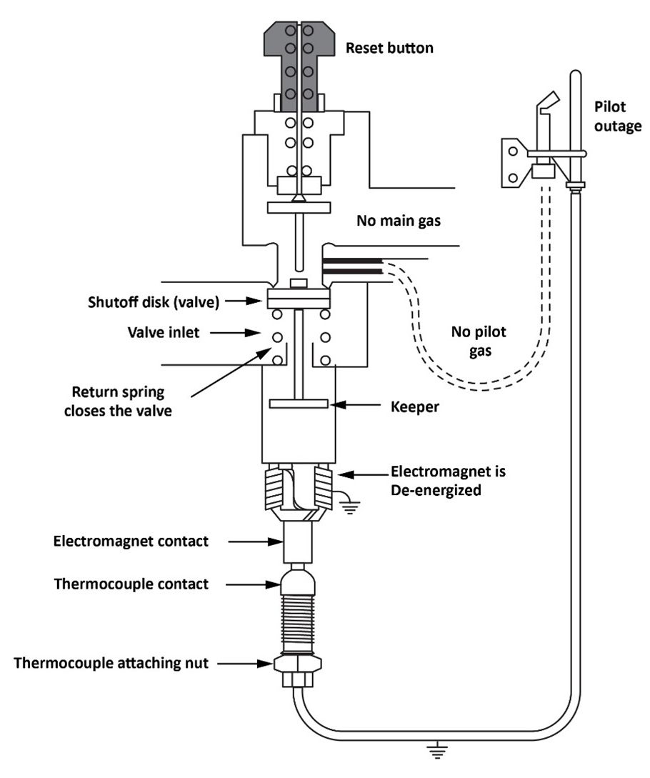
In 100% safe systems, the valve shuts off the gas to both the main burner and the pilot light. Non-100% safe systems only shut off gas to the main burner. The safety shut-off valve is often one component within a combination gas valve. Figure 2 shows the thermocouple connected to the safety shutoff valve, that has been removed and placed in front of the appliance combination gas valve. The gas enters at the connection on the left therefore the safety shut-off valve is the first internal component, that the gas must flow through, within this combined gas valve. Since the closing of the Safety shut-off valve would stop the flow to both the pilot and main burners (Figure 1), this is referred to as a 100% safe system.

Lighting a standing pilot system
These instructions are only meant as a general explanation of standing pilot systems. It is important to thoroughly read and understand the manufactures lighting Instructions before attempting to operate any gas appliances. Before operating any gas appliance smell around the area, if you detect a gas odour do not try and light any appliances and take the appropriate precautions.
- Make sure that the thermostat is turned down so the main burner does not light until you are prepared for it.
- The combination gas valve will typically have a knob with three positions; On, Pilot and Off. Turn the knob to the off position and wait three minutes for any potential residual gas within the combustion chamber to clear.
- Confirm that the pilot burner is not light, the pilot burner will be located within the burner chamber near the end of the pilot tube and thermocouple. This will typically be located within a closed chamber and only viewed though a viewing window.
- Turn the control valve knob to the “Pilot” position.
- Press the manual reset button, this will compress the spring and hold a spring against the electromagnet and will also hold the pilot valve open allowing gas to flow to the pilot burner.
- Light the pilot burner by pressing the spark ignition button repeatedly until you see a pilot light flame.
- Allow the pilot flame to heat the thermocouple for about a minute, or until the pilot relay (electromagnet) holds the pilot valve open.
- Release the reset button.
- The pilot relay electromagnetic coil (solenoid) will hold the shut-off valve open and the pilot should remain lit. While the upper spring will push the reset button back out and open the main gas stop enabling gas to flow to the next chamber within the gas valve.
- The gas valve knob can now be turned to the “on” position and set the thermostat to the desired temperature and the main burner should ignite.
If after the heating period the pilot will not remain lit, wait for 10-minutes before attempting again. After several attempts if the pilot will not remain lit, then the pilot safety circuit may be faulty.
Troubleshooting the Pilot Safety Circuit
If the standing pilot will not remain lit it could be due to a number of problems, including:
- Incorrectly positioned or adjusted pilot flame
- Loose thermocouple connection to the gas valve
- Defective thermocouple
- Defective pilotstat coil
Pilot flame positioning
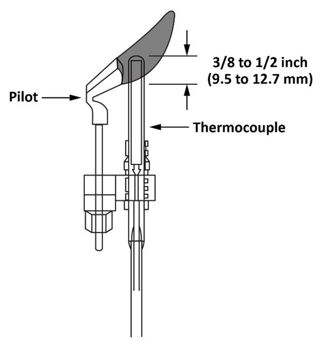
To produce the correct voltage, the thermocouple or thermopile must be correctly positioned in the pilot flame with the proper flame characteristics as shown in Figure 3. It is important that only [latex]\dfrac{3}{8}[/latex] to [latex]\dfrac{1}{2}[/latex] in (10 mm to 13 mm) of the hot junction is heated by the pilot flame, and that no other part of the thermocouple is heated. The greater the temperature difference between the hot and cold junctions, the greater the voltage generated.
Loose thermocouple connection
If the thermocouple connection to the control valve is loose then tighten it a ¼ turn past hand tight. You can also remove the thermocouple and check the terminal to make sure it is not broken or cracked. Ensure the threads are in good order and not restricting the end of the thermocouple from making internal contact.
Thermocouple test
To test for a defective thermocouple, use a millivolt-meter or a multi-meter.
The two tests for a faulty thermocouple are:
- Open-circuit test
- Closed-circuit test
Open-circuit test
A thermocouple should produce approximately 30 mV of potential energy when it is not under load.
A voltmeter that will measure low range dc millivoltage is required to perform this test. Most digital meters meet this requirement; however, only special analogue meters are suitable for this application. Always ensure that the proper meter is used for this test.
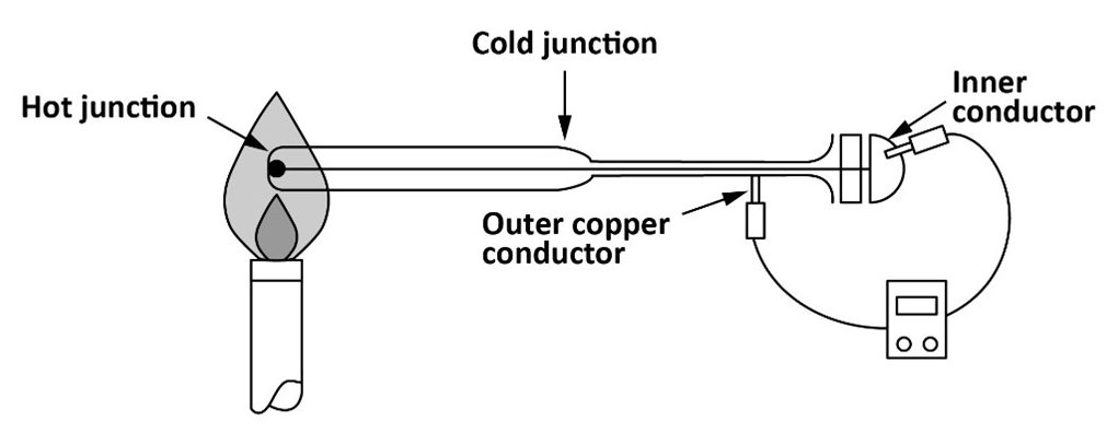
Perform the open circuit test when the thermocouple is not under load; therefore, before starting the test, disconnect the thermocouple from the pilotstat. (Figure 4):
- Select a scale on the millivoltmeter suitable for reading a maximum 30 mV.
- Connect one lead of the meter to the outer constantan conductor of the thermocouple and the other lead to the end of the inner conductor.
- With a pilot flame heating the hot junction of the thermocouple, it should read approximately 30 mV.
- Replace the thermocouple if it produces less than 20 mV.
Inspect the heated end for excessive wear and burned casing, if it appears questionable, the best action is to replace the thermocouple.
Closed-circuit test
All DC voltage sources have an internal or source resistance that can be observed, but not directly measured. To observe the source resistance a second resistance (load) must be connected through a completed circuit. To understand the change in readings between the open and closed-circuit test, and how they relate to the source resistance, it is important to remember the voltage drop laws. The sum of all of the voltage losses will equal the voltage output.
The closed-circuit test will show the millivoltage drop that is being caused by the resistance of the magnetic pilotstat coil compared to the observed amount caused by the internal resistance of the thermocouple itself.
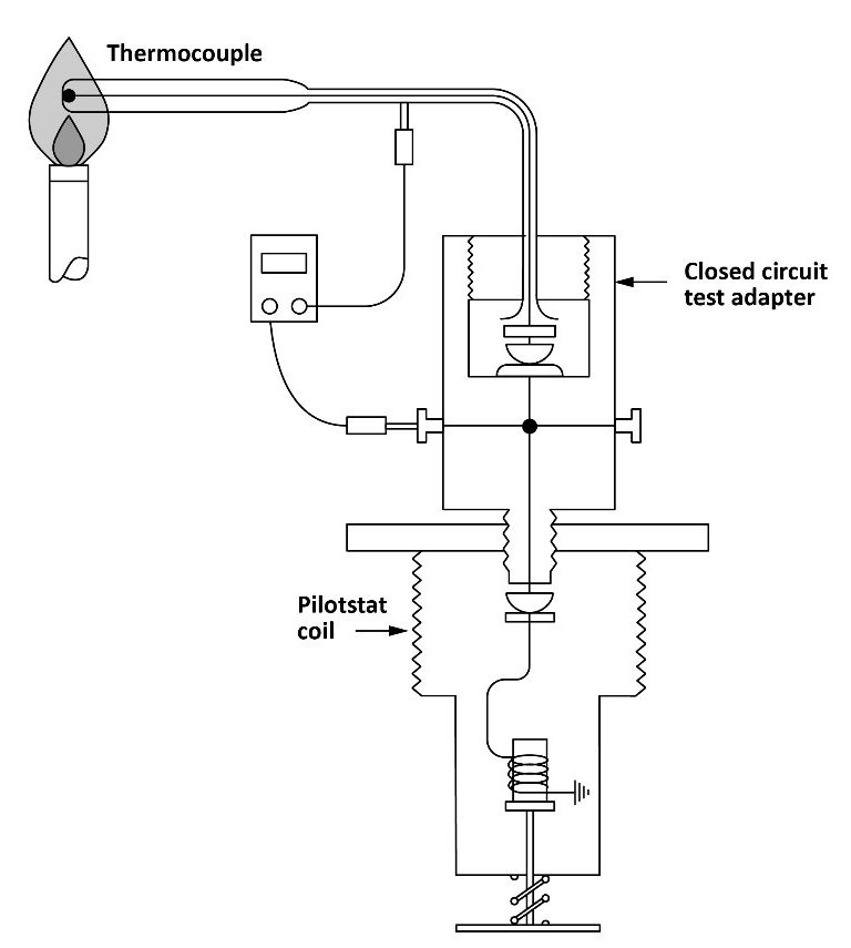
In order perform the closed-circuit test a thermocouple test adapter is required (Figure 5), which will enable the meter to be connected in parallel with the load/coil.
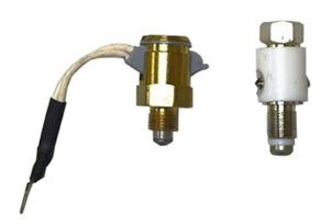
This will test the performance of the thermocouple under load conditions. At the end with the same connections setup, the pilotstat coil can be tested to determine its condition (Figure 6).
A closed-circuit test is completed as follows:
- Disconnect the thermocouple from the pilotstat and install the test adapter.
- Reconnect the thermocouple to the top of the test adapter and relight the pilot burner.
- Connect one test lead to the outer conductor of the thermocouple and the other test lead to the side terminal on the test adaptor (watch polarity).
- Since the side terminal of the test adaptor is internally connected to the inner conductor of the thermocouple, a voltage drop test can be performed while the circuit is energized. This test will measure the voltage drop across the pilotstat coil only, the difference between this reading and the open circuit test represents the energy that is lost within the internal resistance of the thermocouple itself.
- The meter should read about 15 mV if both the thermocouple and Pilotstat are in good condition.
- Notice that this is approximately one-half of the open circuit voltage, the other half of the energy is lost within the internal resistance of the thermocouple itself.
- If the closed-circuit voltage should drop to below 10 mV, replace the thermocouple as it is consuming more than its share of the energy produced.
Pilotstat magnetic coil test
A voltage drop across the coil of 2 mV to 5mV should create enough of a magnetic field to operate the pilotstat and hold the valve open. Also, of the valve stays open with a voltage drop below 2 mV it is sticking or the spring has weakened.
These conditions can be checked using the same meter connection setup as the closed-circuit test (Figure 6):
- Connect one lead of the millivoltmeter to the outer constantan conductor and the other to the terminal on the side of the test adaptor (check polarity).
Under normal operation, the voltage reading is between 10 and 15 mV. - Blow out the pilot gas and allow the thermocouple to cool.
As it cools, watch the millivoltmeter and notice that the reading is slowly decreasing. - The coil of the pilotstat should create enough magnetic field to hold the valve open until the millivoltage drops between 5 and 2 mV.
This drop out of the coil should take place within 90 seconds from flame failure, to meet the requirements of the CSA B149.1 Gas Code

Now complete Self-Test 3 and check your answers.
Self-Test 3
Self-Test 3
- What is the primary purpose of a thermocouple?
- To monitor the main burner
- To energize the gas valve
- To prove that the pilot is lit
- To supply power to the thermostat
- What is the maximum time allowed in the event of pilot outage for the thermocouple to cool down and stop the flow of gas to the burner?
- 45 seconds
- 60 seconds
- 90 seconds
- 120 seconds
- What type of current do thermocouples and thermopiles produce?
- AC
- DC
- 3-phase
- Magnetic
- A thermocouple must be under load to perform an open circuit test. True or False?
- True
- False
- What reading should an open circuit test on a thermocouple produce?
- 9 mV
- 17 mV
- 30 mV
- 250 or 750 mV
- What does a closed-circuit test show?
- Pilot stat dropout millivolts
- Millivolt output not under load
- Millivolt output unheated thermocouple
- Millivolt maintained under load
- A thermocouple should be replaced if it cannot produce a closed circuit reading of more than.
- 2 mV
- 9 mV
- 20 mV
- 30 mV
- During a pilotstat coil test at what mV reading should the coil drop out?
- Between 2-1 mV
- Between 5-2 mV
- Between 20-15 mV
- Between 30-15 mV
Check your answers using the Self-Test Answer Keys in Appendix 1.
Media Attributions
- Figure 1 "Thermocouple safety shut-off valve system" by Camosun College is licensed under a CC BY 4.0 licence.
- Figure 2 "Thermocouple connected to the removed safety shutoff valve" by Camosun College is licensed under a CC BY 4.0 licence.
- Figure 3 "Standing pilot flame position" by Camosun College is licensed under a CC BY 4.0 licence.
- Figure 4 "Open thermocouple test" by Camosun College is licensed under a CC BY 4.0 licence.
- Figure 5 "Thermocouple adapters" by Camosun College is licensed under a CC BY 4.0 licence.
- Figure 6 "Closed thermocouple circuit test" by Camosun College is licensed under a CC BY 4.0 licence.
