Compressed air is atmospheric air which has been mechanically forced (by a compressor) into a storage chamber and then, with a means of control, released to perform a specific task. Compressed air is used by many industries in a large variety of applications – one of the major uses is the spray painting industry for atomizing materials. Other uses are air-operated tools, air control devices, agitating operations, pneumatic water supply systems, temperature and instrument control, fire protection sprinkler systems, liquid or solid transfer by compressed air, and even rodent control.
Atmospheric air, (the air we breathe) consists of approximately 78% nitrogen and 21% oxygen. Air has weight and this weight is called atmospheric pressure. At sea level, this pressure is 101.3 kPa (14.7 psi). This means that the air pressure exerted on every square inch of the earth’s surface and everything on the earth’s surface at sea level is 14.7 pounds per square inch. This pressure is also exerted to the sides and upwards from the earth; therefore, air at the compressor intake, enters at the pressure of 14.7 psi (absolute pressure).
Compressed air is measured on the basis of volume of air used at a given pressure. The reference to volume of compressed air is always a measurement of air in its free state; or standard atmospheric condition (SCFM). Standard air has been defined as being 200 Celsius (680 F), having an atmospheric pressure of 101.3 kPa (14.7 psi), and 36 % relative humidity. Standard air is used when tests are made and efficiencies computed; standard air is also the basis for rating compressors as to volume deliver capabilities.
Altitude
Atmospheric pressure and density of air decrease as the altitude increases. Due to the lower pressure and lesser density of the air, a smaller (output) quantity of air is would be delivered by the compressor at the higher elevation. Air delivery of a compressor is reduced by approximately 3 percent for every 1000 feet in elevation above sea level.
Temperature
There is an adverse effect on an air compressor’s performance when the inlet air temperature rises above normal. Should the temperature rise above 200 Celsius there will be a loss of air delivery equivalent to 2% for every 5.60 C increase in air temperature. For example: if a compressor is operating on a summer day, or in a heated room with an air temperature of 370 C, there would be a 6 percent drop in the volume of air delivered from its rated capability. Therefore, have the compressor installed in a cool section of the plant or near a window, where good air circulation can be had, or install the air intake outside the building on the cool side (North) and pipe the air intake directly into the compressor.
Heat of Compression
Air from the discharge side of a compressor is hot because it has been compressed. The temperature of discharged air ranges, depending upon the type of compressor and the working pressure. The higher the working pressure, the higher the amount of heat generated.
When this heated air enters the air receiver, we sometimes get a false reading on the air pressure gauge. As the heat is dissipated from the air receiver, the temperature drops and the pressure will drop even though no air is being used. This is because hot air requires more space and, conversely, cold air, having greater density, requires less space.
In order to have a true volume or pressure of air in the storage tank or air receiver, the temperature must be brought to room or ambient temperature. This is done by means of an aftercooler. With a true volume of air in the receiver, the on-off cycle of the compressor is kept to a minimum. When air is expanded, due to high intake temperatures, the on-off cycle will be increased as the air in the receiver cools.
The hazards associated with compressed air systems are not easily recognized, as air is often perceived as harmless. As with any compressible fluid under pressure, this perception is far from reality. Some examples of the types of injury that a compressed air system can cause are:
- When used to remove dust and debris from a worker’s body, air may be forced through the skin and could result in an air embolism with potentially fatal results. Also, by driving particles of bacteria under skin, a serious condition such as flesh-eating disease can occur.
- Exhausting air can produce noise levels that may result in damage to a person’s hearing. Exhaust air released by the tools is often not muffled, exposing workers to high decibel levels.
- Particles may be accelerated to a velocity that can result in injury.
- Operating at the incorrect pressure or flow can cause excessive force, resulting in serious injury.
- Air hoses that are the wrong size for the tool or in poor condition with kinks can cause variations in the pressure exerted to the tool. This may cause injury to the operator.
- Severed or broken hoses can thrash violently until the air supply is isolated.
- The tool may discharge air contaminated with oil or antifreeze, causing a respiratory hazard.
- Pneumatic tools may not be grounded or double insulated. Contact with an electrical source could cause shock.
Compressed air systems generally are separated into two subsystems (Figure 1): the supply side and the demand side.
The supply side includes the equipment at the source such as compressors, air treatment devices and primary storage. The supply side produces air flow rates that are measured in standard cubic feet per minute (SCFM), a specification that indicates the volume of air an air compressor can provide at a certain pressure.
The demand side is basically distribution piping, secondary treatment equipment, and the end use tools. A properly designed and installed demand-side system minimizes air pressure differentials and reduces waste of air due to leakage and drainage.
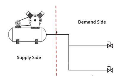
Figure 1 Basic Compressed Air System
The supply side includes the equipment at the source such as compressors, air treatment devices and primary storage. The supply side produces air flow rates that are measured in standard cubic feet per minute (SCFM), a specification that indicates the volume of air an air compressor can provide at a certain pressure.
The demand side is basically distribution piping, secondary treatment equipment, and the end use tools. A properly designed and installed demand-side system minimizes air pressure differentials and reduces waste of air due to leakage and drainage.
Supply Side Сomponents
Supply-side components (Figure 2) could include the following:
- air intake
- air compressor
- motor and controls
- intercooler
- aftercooler
- moisture separators
- receivers
- primary treatment equipment and accessories
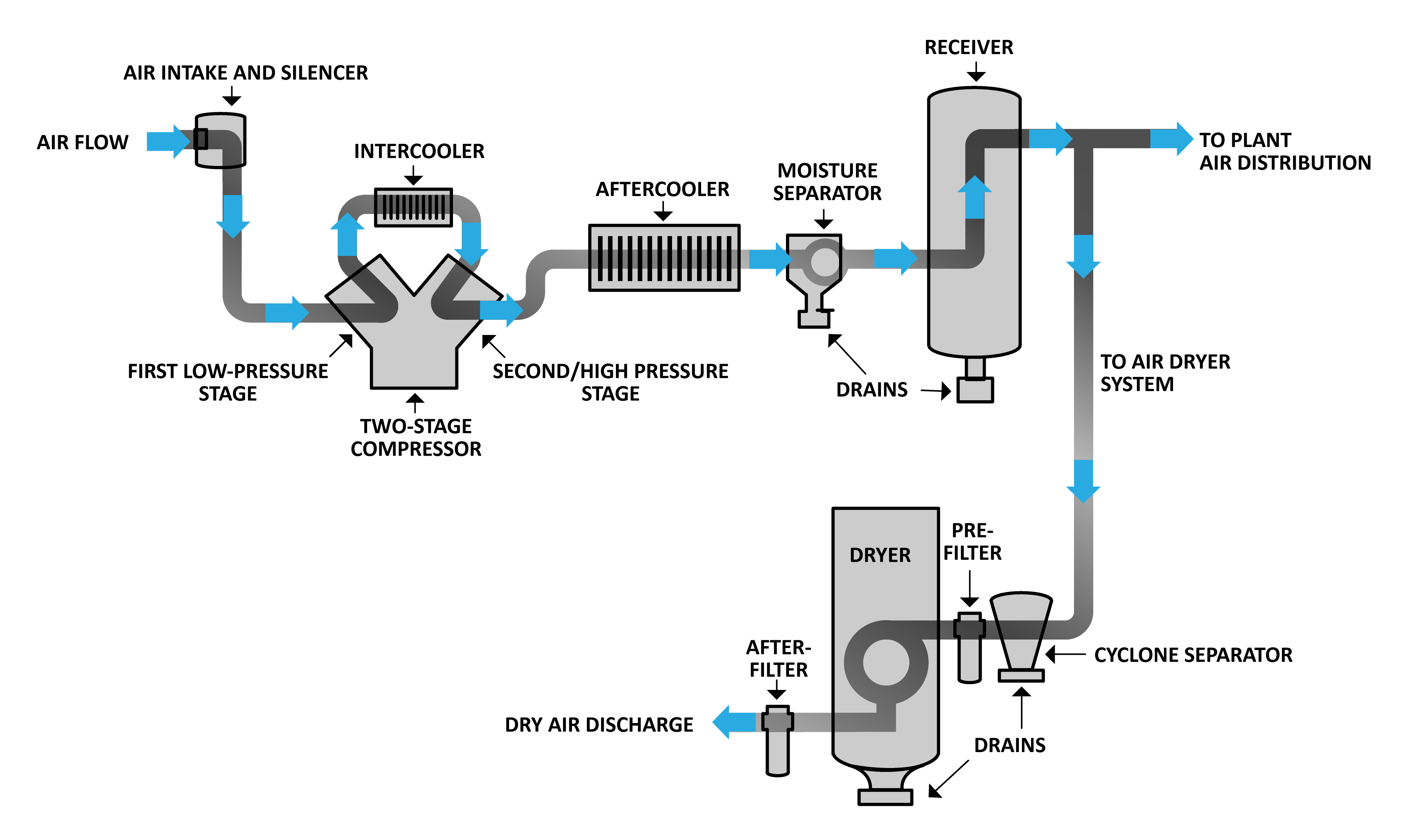
Figure 2 Supply Side Components
Compressed air supply auxiliary equipment includes the compressor intercooler, aftercooler, filters, separators, air dryers, heat recovery equipment, lubricators, pressure regulators, air receivers, condensate drains and automatic drains. These devices associated with the air compressor help to condition compressed air to the required specifications.
Compressor types and operation
There are two basic compressor types, which compress air in different ways:
Reciprocating compressors
Major types of reciprocating compressors include:
- reciprocating single acting (single- and two-stage)
- reciprocating double acting
- reciprocating diaphragm
- reciprocating rocking piston type
Reciprocating single acting single-stage
Reciprocating single acting (single-stage): Air is drawn in from the atmosphere and compressed to final pressure in a single stroke (Figure 3). Single-stage compressors are generally used for pressures of 70 to 135 psi (490 to 945 kPa).
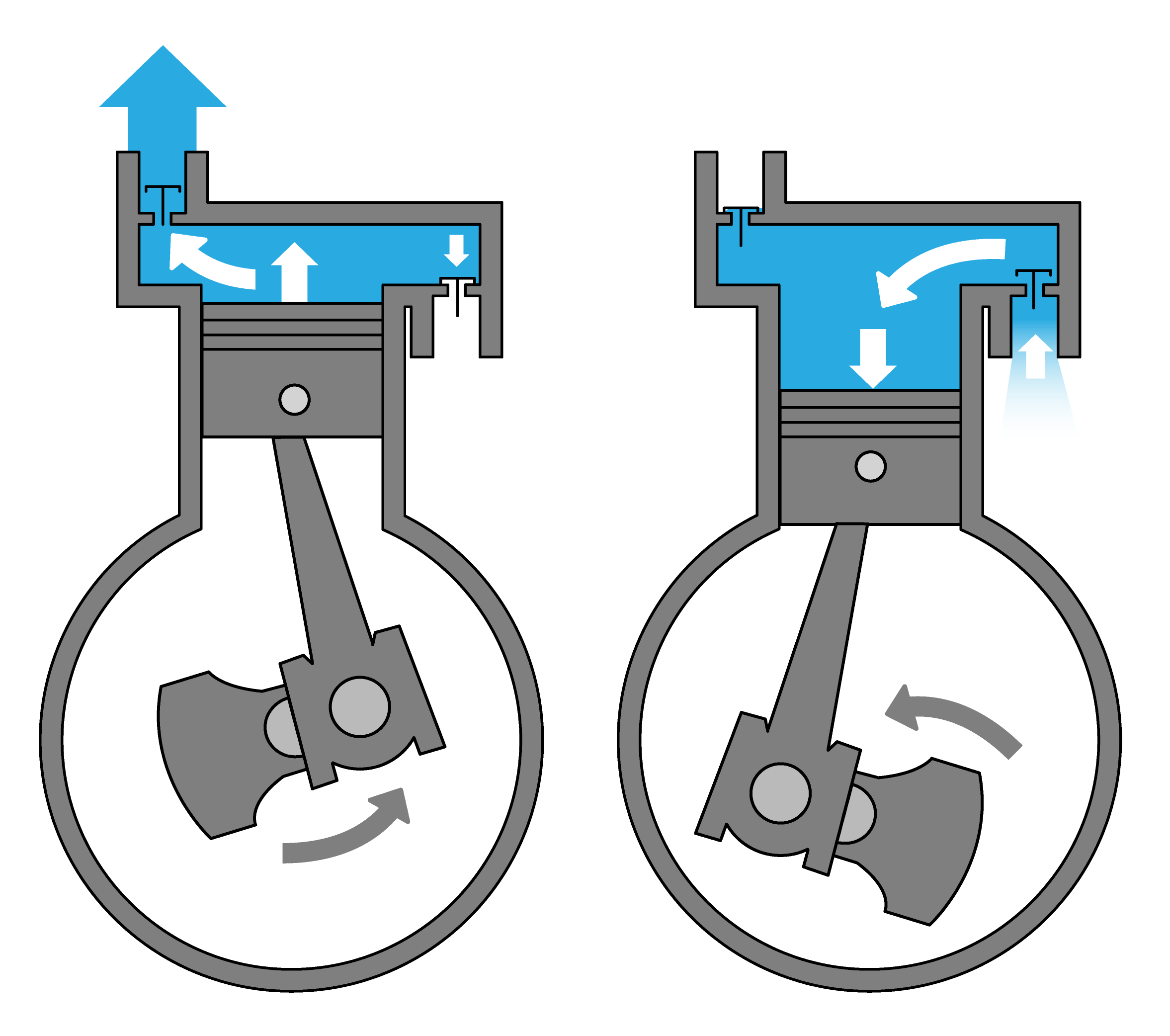
Figure 3 Single-stage reciprocating single acting air compressor
Reciprocating single acting (two-stage)
Reciprocating single acting (two-stage): This design (Figure 4) has a minimum of two cylinders in series:
- low-pressure cylinder (largest)
- high-pressure cylinder (smallest)
The reason why the cylinders are different sizes is that, as the air is passed from cylinder to cylinder it requires less space at each stage. Air is compressed once in the large cylinder and then sent through an intercooler, which reduces discharge air temperatures. The air is compressed again in the smaller cylinder. Two-stage air compressors produce a larger volume of air at higher pressures than smaller single-stage compressors.
Figure 4 Two-stage reciprocating single acting air compressor
Reciprocating double acting
Reciprocating double acting: This design has compression chambers on both sides of the piston (Figure 5). On the downstroke, air is drawn in at the top end of the piston while air is compressed at the bottom end. On the upstroke, air is drawn into the bottom end while air is compressed at the top end. Double acting reciprocating compressors may have one or more stages and are typically water-cooled. Sizes range from around 40 horsepower (30 kW) to over
1000 horsepower (745 kW). Very few manufacturers still produce the double acting reciprocating compressor because it is quite expensive to produce, requires special foundations to handle vibration and requires frequent extensive maintenance.
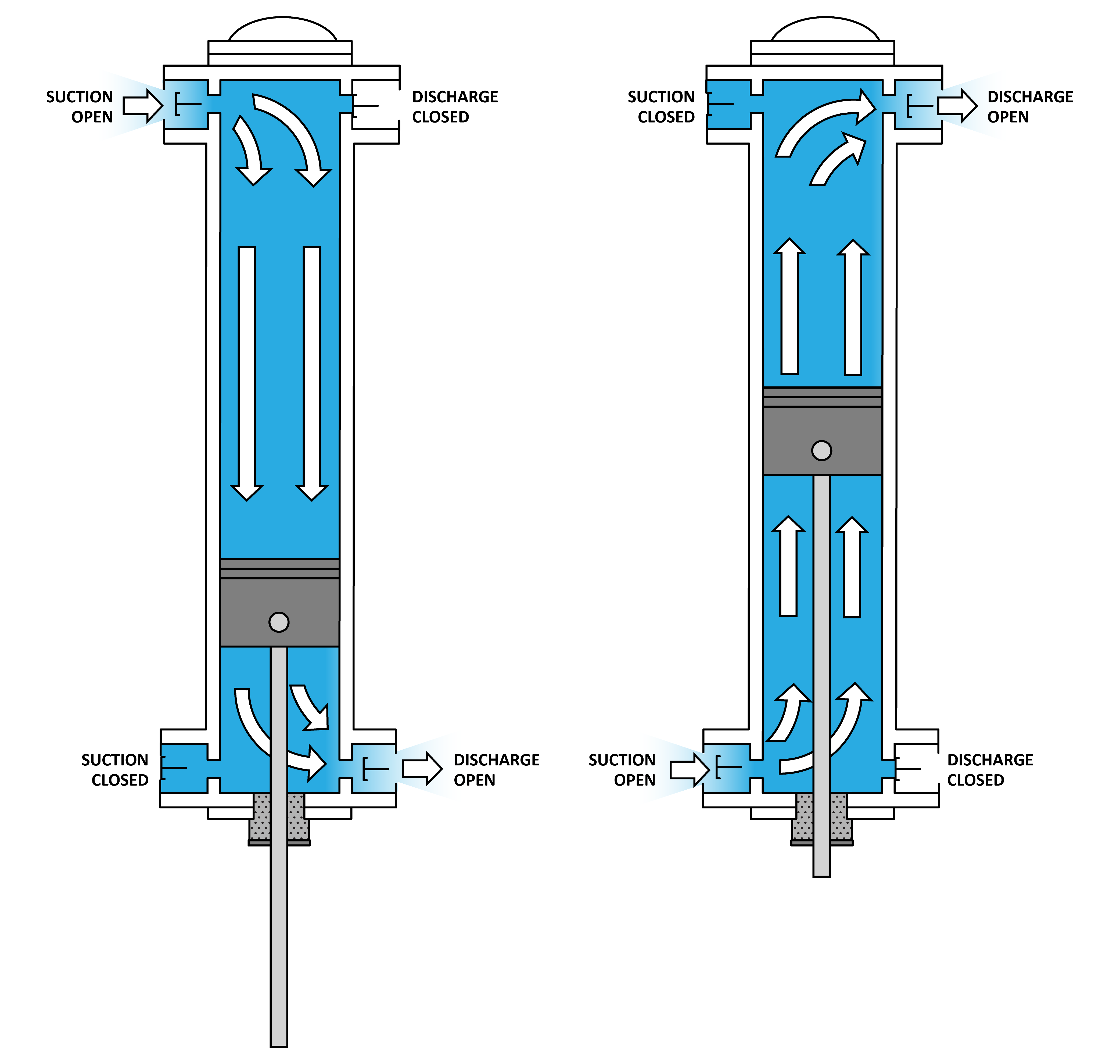
Figure 5 Single-stage reciprocating double acting air compressor
Reciprocating diaphragm
Reciprocating diaphragm: This design is a variation of the reciprocating compressor. The reciprocating diaphragm compressor (Figure 11) develops pressure through the reciprocating or oscillating action of a flexible disk actuated by an eccentric cam. Since a sliding seal is not required between moving parts, this design is not lubricated. Diaphragm compressors are often selected when no contamination is allowed in the output air line or atmosphere. Diaphragm compressors are limited in output volume and pressure, and they are used most for light-duty applications.
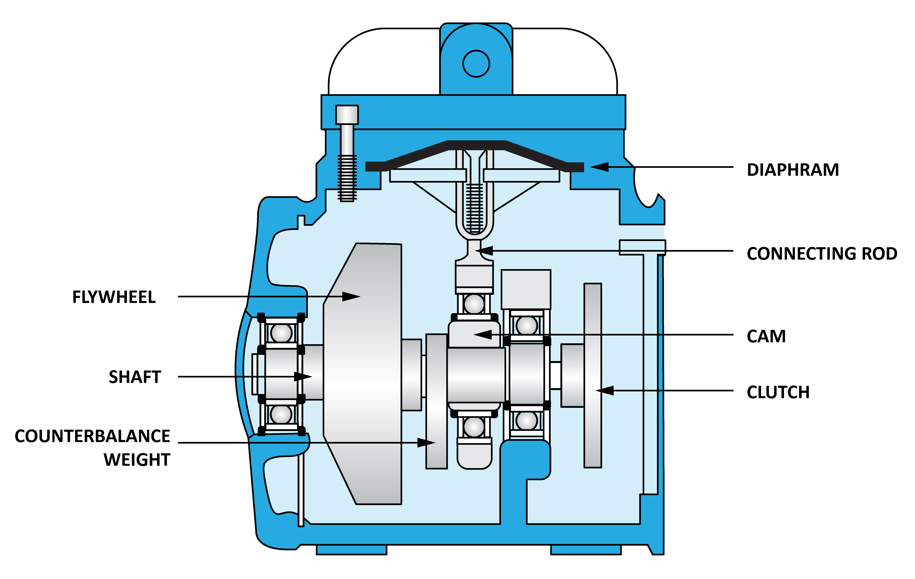
Figure 6 Reciprocating diaphragm single acting air compressor
Reciprocating rocking piston
Reciprocating rocking piston: This design is a variation of the reciprocating piston compressor. It develops pressure through the reciprocating action of a one-piece connecting rod and piston. The piston head rocks as it reciprocates. These compressors (Figure 7) use non-metallic, low- friction rings and do not require lubrication. Rocking piston compressors are available in single and dual stage and are generally used for pond irrigation systems.
Rotary air compressors
Major types of rotary air compressors include:
- rotary sliding vane
- rotary helical screw
- rotary scroll air
Rotary sliding vane
In this design, pumping action is produced by a series of sliding, flat vanes as they rotate in a cylindrical housing. As an eccentrically mounted rotor turns, the individual vanes slide in and out of their slots by centrifugal and pressure-loading forces (Figure 8). This creates a series of air compartments of unequal volume against the wall of the housing. These compartments get larger during the suction part of the cycle, creating vacuum at the intake port, and smaller during the discharge portion of the cycle, creating pressure at the exhaust port. The vacuum and pressure flows are free of pulsation because the inlet and exhaust ports do not have valves, and the air is moved continuously rather than intermittently.
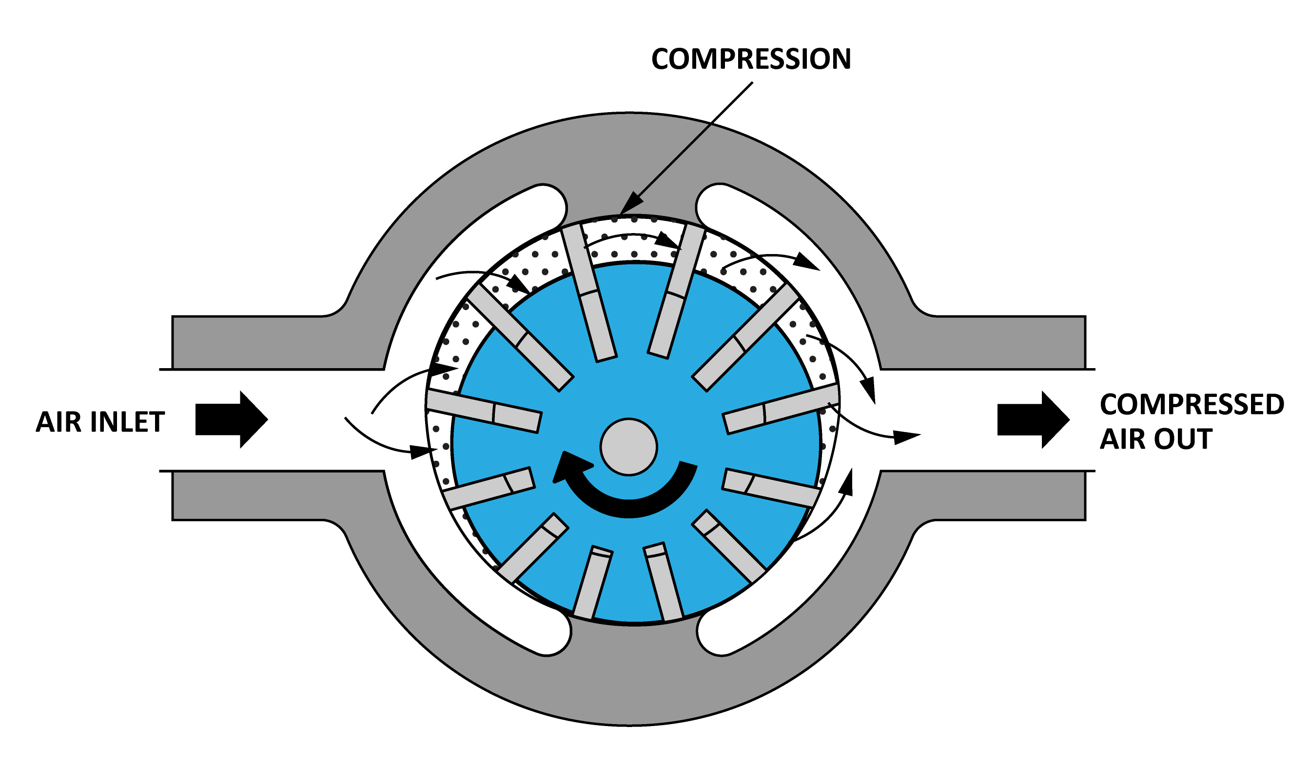
Figure 6 Reciprocating diaphragm single acting air compressor
Rotary screw
This design uses two rotors (helical screws) to compress the air (Figure 9). The rotors are of different shape but are machined to mesh together with a small clearance space between them. When the rotors start turning, air is drawn in on one side (the suction side), where it is trapped between the rotors. Since the rotors are continuously turning, the air is pushed to the other end of the rotors (the pressure side) and new fresh air enters to replace it.
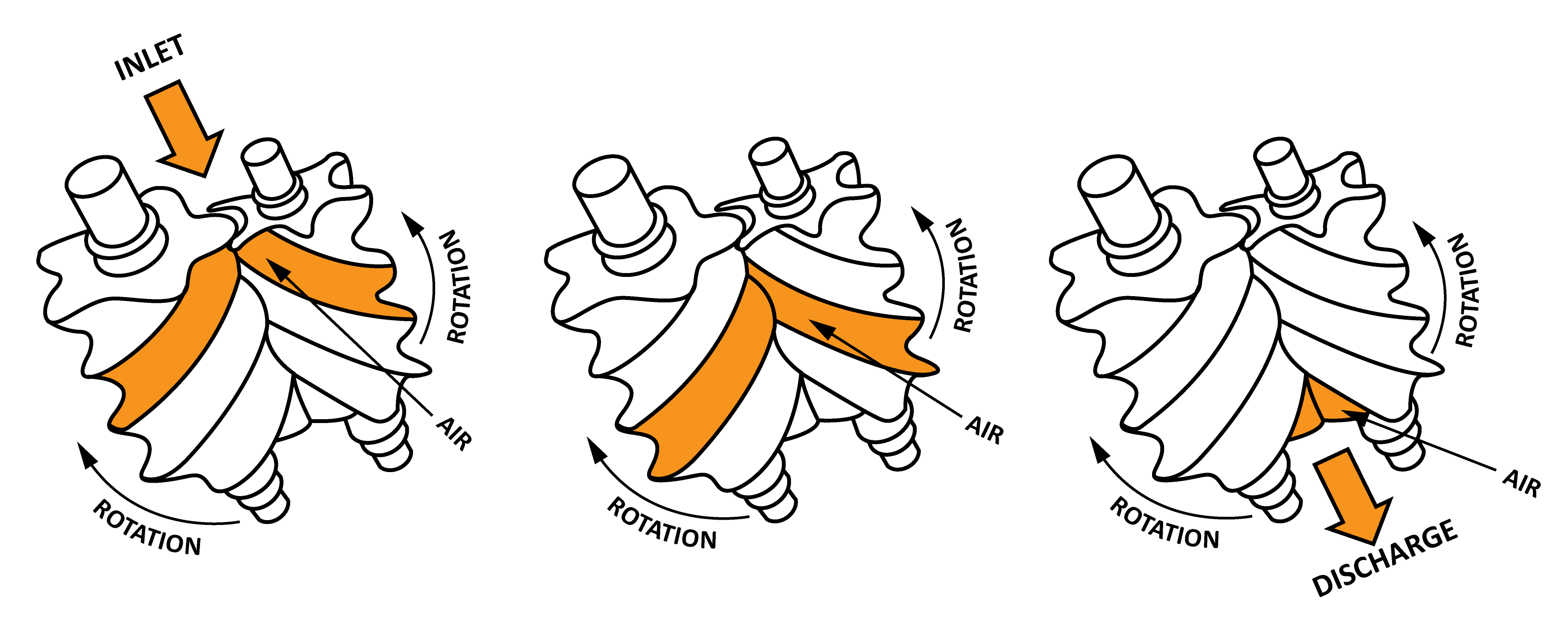
Figure 9 Compression in a twin-screw compressor
Advantages of the rotary screw compressor include smooth, pulse-free air output in a compact size with high output volume over a long life. For manufacturing processes that require 100% duty cycle a rotary screw compressor is often used, as they are designed to go all day without stopping, whereas a piston compressor normally works better when it can take a break.
Rotary screw compressors are either oil injected or oil free. In the oil injected type a motor drives the male rotor which in turn drive the female rotor, with a thin film of oil between them to lubricate and seal the gaps between the rotors to provide compression. Oil lubricated compressors will have an internal oil handling system to separate and treat the air/oil mixture that leaves compressor (Figure 10), so that the oil can be recovered and injected back into the compressor (Figure 10).
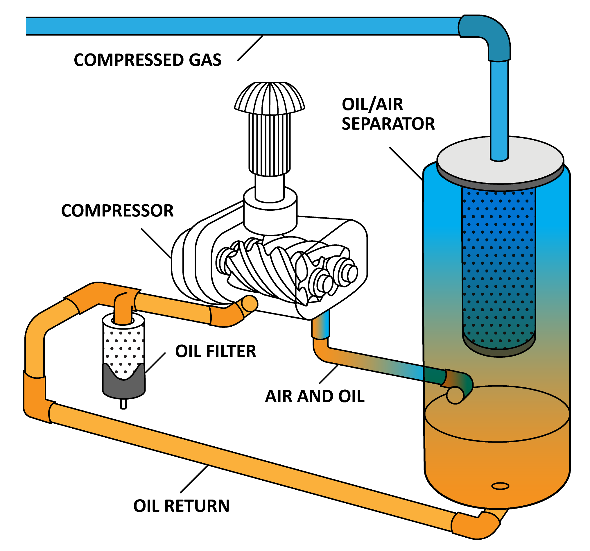
Figure 10 Oil injected rotary screw compressor
Oil free rotary screw compressors have rotors with tighter tolerances to achieve compression. There are additional timing gears to maintain alignment as they must spin at much higher speeds than an equivalent oil injected type (Figure 11). Although oil is not used in the compression stage it is still required to lubricate and cool the bearing and gears.
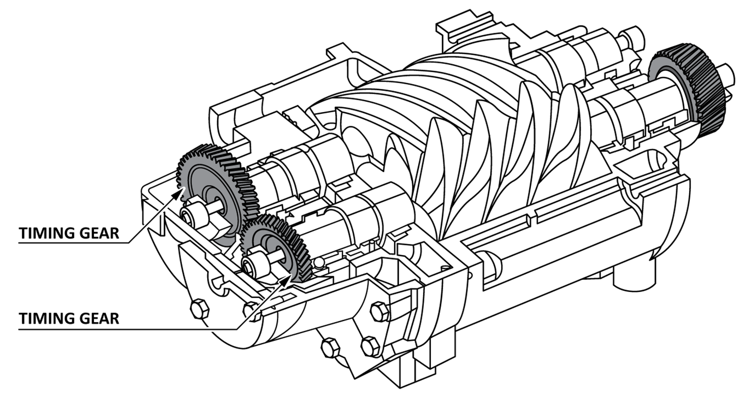
Figure 11 Oil-free screw compressor with synchronizing helical screws to maintain very small rotor clearances
Rotary scroll
In this design, the compressor contains two spiral elements (Figure 12). One moves in eccentric circles and the other is stationary. Air is drawn in between the two spiral elements on the suction side and is transported to the centre of the spiral. Due to the reduced volume at the spiral centre, the air is compressed. It takes about 2.5 turns for the air to reach the centre exhaust pipe.
The big advantage of this type of compressor is the quiet operation. Since there is only one moving part and there is no oil, maintenance is very easy.
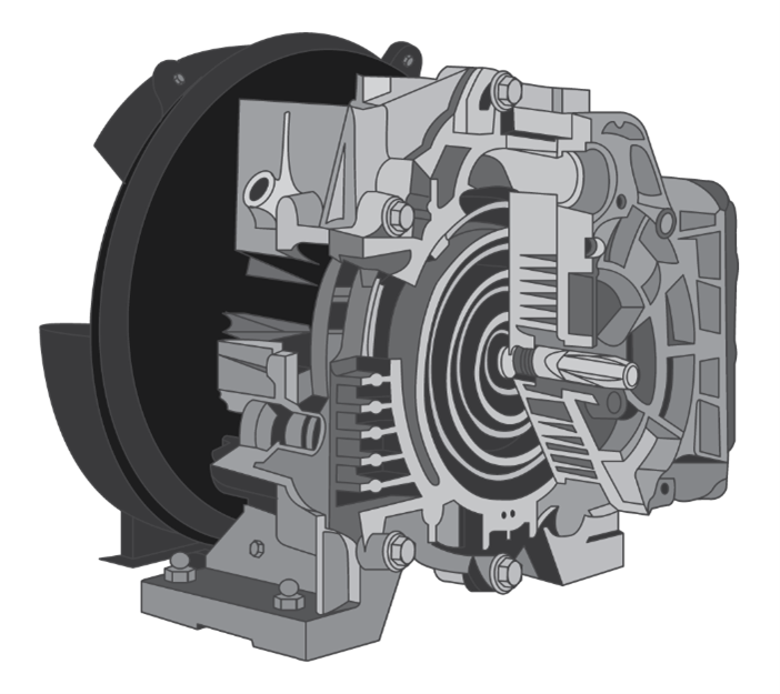
Figure 12 Rotary scroll compressor cross section
Intercooler
In a multi-stage unit compressor (Figure 13), the air is compressed in succeeding cylinders (stages), absorbing heat along the way. An intercooler is installed between the stages to help cool the air before it is introduced into the next stage for further compression. This heat rejection process contributes to the compressor’s efficiency.
Intercoolers in multi-stage units may use air cooling or water cooling. In air cooling the compressed air passes through a chamber equipped with cooling fins that are exposed to the ambient air. The fins provide an increased surface area that allows the heat energy to move more readily to the surface and to escape into an area of lower temperature.
Water cooling is achieved by passing the compressed air through a water-cooled heat exchanger. Cool water flows around the outside of the air line, quickly taking heat away and cooling the compressed air rapidly.
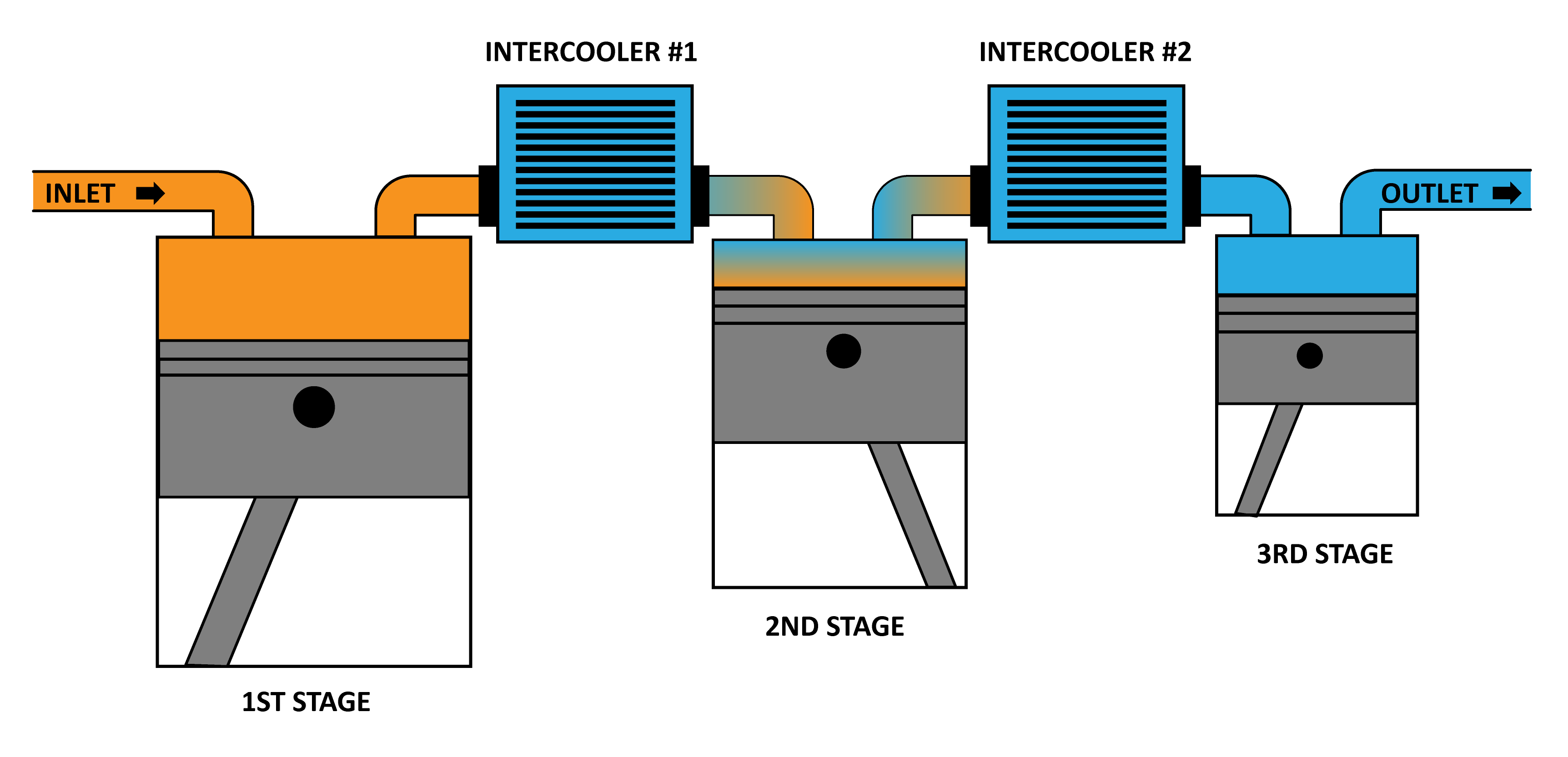
Figure 13 Three-stage compressor with twin intercoolers
Aftercooler
An aftercooler is a heat exchanger that cools the hot compressed air to condense the water vapour that otherwise would condense in the piping system. The aftercooler can be either air or water cooled (Figures 14) and is installed after the last stage of compression. They are generally equipped with a water separator with automatic drainage. Approximately 80–90% of the condensate is collected in the aftercooler’s water separator.
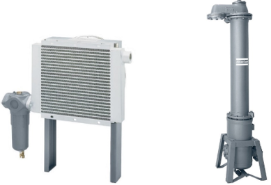
Figure 14 Air-cooled aftercooler (left) Water cooled after cooler (right)
Compressor manufacturers may include aftercoolers within the compressor package. In general these compressors are referred to as integral aftercoolers. A stand-alone or freestanding aftercooler is also available for some installations and should be placed close to the compressor.
Air filters
Compressor air filters can be found in two places in the compressed air system:
- at the air-intake to the air compressor
- in the compressed-air piping, between the compressor and the end user’s equipment, air tools, etc.
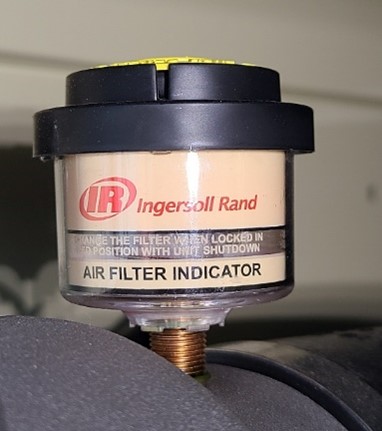
The intake-air filter (Figure 15) is the most important filter on your compressor because dust will cause wear to the compressor element, valves and other moving parts.
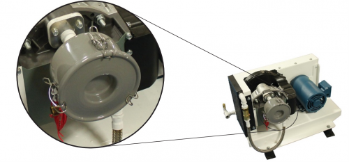
Figure 15 Air compressor intake filter
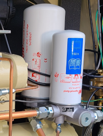
Compressed air filters downstream of the air compressor, also known as line filters, are generally required to remove contaminants, such as particulates, condensate and lubricant. Numerous choices for filtering are available; the choice depends on the application of the air and the required degree of cleanliness.
Generally, the finer the filter, the greater the pressure differential (pressure drop) across the element. Particulate filters are used to remove solid particles and have the lowest differential. Coalescing filters that are used to remove lubricant and moisture usually have the highest differential. For oil and particulate filters, use filtration only to the level required by each application.
Moisture Separators
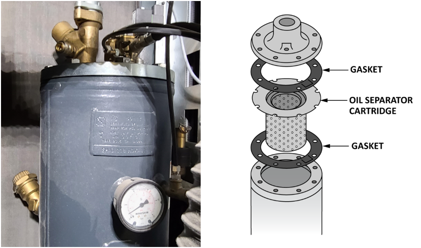
Untreated compressed air is saturated with water vapour which can cause system problems such corrosion and growth of micro-organisms. Moisture separators are devices that remove entrained liquids from the air. They are installed following aftercoolers to remove the remaining condensed moisture. Moisture separators should not be confused with oil separators, which are used within lubricated rotary screw compressors to recover lubricant from the compressed air discharge, and return it to the compressor injection chamber.
Moisture separators come in two types:
- Centrifugal (Cyclone)
- Coalescing
Centrifugal separators direct the air at an angle into a cone shaped chamber which creates a spinning vortex. The rotary motion forces the higher density moisture to the outside, which then falls by gravity to a bowl where it can then be drained off (Figure 16). Auto drains help empty the filter bowl regularly, otherwise the bowls do need to be manually drained regularly to prevent water and other debris from being forced back into the air stream.
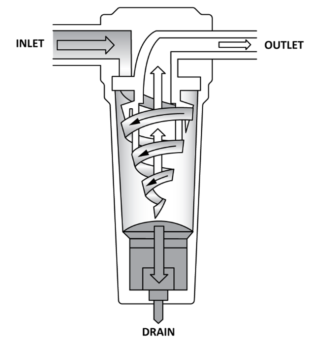
Figure 16 Centrifugal separator
A coalescing separator flows the air from the inside to the outside of a filter element. Solid particles get captured in the filter cartridge. Fluid particles, such as condensate or oil, coalesce or attach to larger droplets, which flow off and are caught in the filter bowl (Figure 17). The filter cartridges must be replaced regularly.
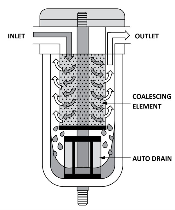
Figure 17 Coalescing separator
Oil and Water Separation
The moisture withdrawn by separators or refrigerant dryers contain oils from the ambient air drawn into the compressor intake. The amount of oil in the compressed air is primarily dependent upon the ambient air quality, which can vary depending on the intake location. Discharging even a small quantity of oil into the sewage system is illegal. An oil and water condensate separation system (Figure 18) removes all of the contaminated condensate from the compressed air and then separates the oils and water through a multistage cascade filtration system. The clean water can then be discharged into the sewage system and the captured oil is properly disposed when it is time to change the filter.
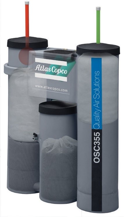
Figure 18 Oil/water condensate separator
Receivers and air storage
An air receiver tank (Figure 19) is an extremely important part of any compressed air system and provides the following benefits:
- It acts as a reservoir of compressed air for periods of peak demand.
- It reduces wear and tear on the motor by reducing excessive compressor cycling.
- It helps to remove water from the system by allowing the air a chance to cool.
- It minimizes pulsation in the system caused by a reciprocating compressor or a cyclic process downstream.
Much the same as a water reservoir provides water during times of drought and stores water during the wet times, an air receiver tank compensates for peak demand and helps balance the supply of the compressor with the demand of the system. You will need to calculate the correct tank size for the air requirements to avoid installing an undersized receiver, which would result in insufficient air volume and cause excessive cycling. An oversized receiver wastes energy by requiring the compressor motor to run longer. A general sizing guideline is three to five gallons per cfm at full load.
It is important to note that receiver tanks are pressure vessels and are required by law to have a pressure relief valve and a pressure gauge. The relief valve should be set to 10% higher than the operating pressure of the system.
It is also important to install either a manual or automatic drain on the receiver tank to remove water from the system. A coalescing filter and air dryer are best placed downstream of the receiver tank. Some systems use two receivers, the additional tank, also known as the dry tank, is placed downstream of the treatment components to store clean dry air.
The receiver piping should enter low and exit high, to promote moisture separation and prevent accumulated condensate from traveling downstream. The tank should be located in a cool area and not in the path of the compressor or dryer’s exhaust flow.
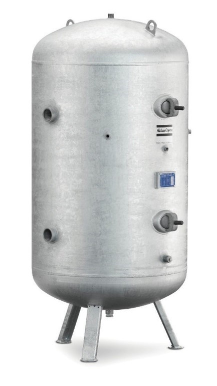
Figure 19 High-pressure air receiver
System drains
Drains are needed at all separators, filters, dryers and receivers in order to remove the liquid condensate from the compressed air system. Failed drains can allow slugs of moisture to flow downstream which can overload the air dryer and foul end-use equipment.
Air dryer
Compressed air leaving the compressor aftercooler and moisture separator is normally warmer than the ambient air and fully saturated with moisture. As the air cools, the moisture will condense in the compressed air lines. If the air is subject to freezing temperatures or is used in an application where water vapour in the air can be harmful to the process, an air dryer is required.
There are four general types of air dryers used in compressed air systems:
Refrigeration dryers
The dew point is the temperature at which the air is fully saturated and cannot hold additional water vapour. As the name implies refrigerated dryers (Figure 20) work by cooling the air to lower temperatures, below the dew point, thus condensing and collecting much of the water vapour. These dryers can not be installed in areas exposed to freezing environments.
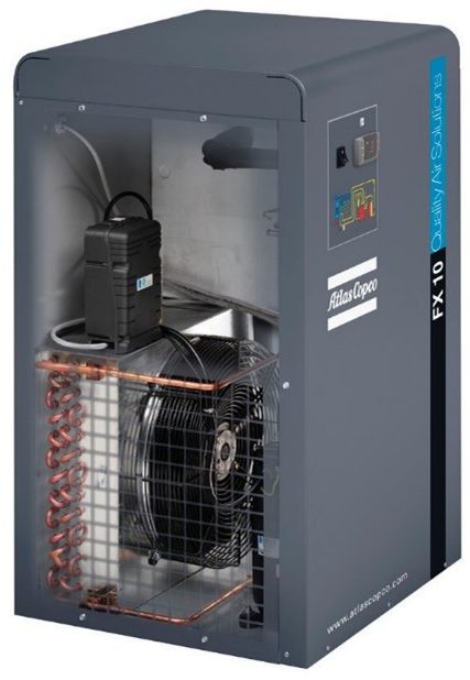
Figure 20 Refrigerant air dryer
Deliquescent dryers
A deliquescent dryer (Figure 21) is basically a tank full of salt tablets. As the compressed air passes through the salt, the salt attracts water and dissolves into a brine that can be drained off. These are the least expensive dryers to purchase and maintain because they have no moving parts and require no power to run. The operating cost consists of the cost of more salt tablets once they are depleted. The fact that they need no electricity to run and that the water they remove from compressed air is part of a salt brine with a lower freezing point also makes them desirable for winter operation outdoors.
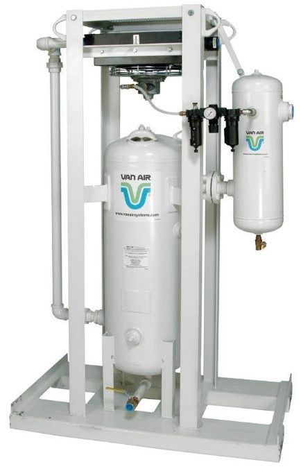
Figure 21 Deliquescent air dryer
Desiccant dryers
Desiccant dryers, also known as regenerative dryers, have two towers filled with desiccant (Figure 22). Desiccant materials are porous and absorb water vapour molecules. That process is reversible, and when the pores contain enough water vapour, exposure to heat or dry air will cause the water vapour to be released. In operation, one tower is drying the incoming air while diverting a percentage of that super dry air to the other tower to purge it of previously accumulated moisture. The towers switch their roles constantly and therefore the term “regenerative” is used to describe this system. This technology is a good choice when the compressed air will be exposed to freezing conditions or where instrument quality air is required, as they virtually ensure that downstream compressed air lines are protected from moisture, condensation and freeze ups.
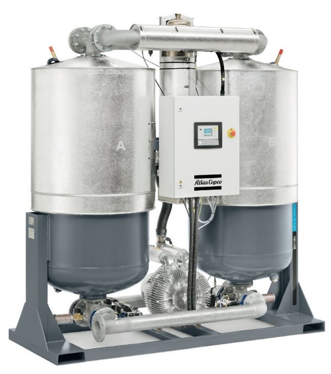
Figure 22 Desiccant air dryer
Membrane air dryers
Membrane air dryers use specially formulated membrane microtubes (Figure 23) that are an excellent medium for producing dry air from standard compressed air.
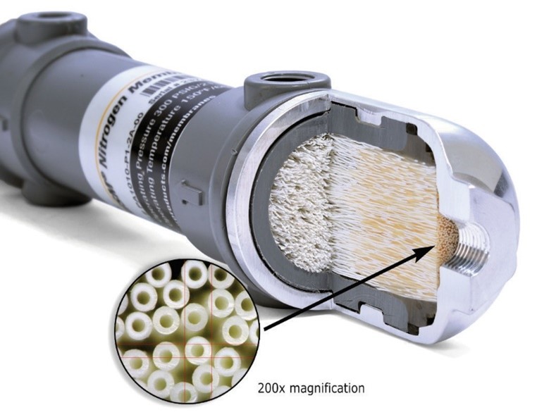
Figure 23 Membrane dryer microtubes
As air passes through a bundle of hollow membrane tubes, the water permeates the membrane walls (Figure 24). The dried air continues down the tubes and into the downstream air system. A small fraction of the dry air is then directed along the outside surface of the membrane to “sweep” the moisture-laden air away from the membrane.
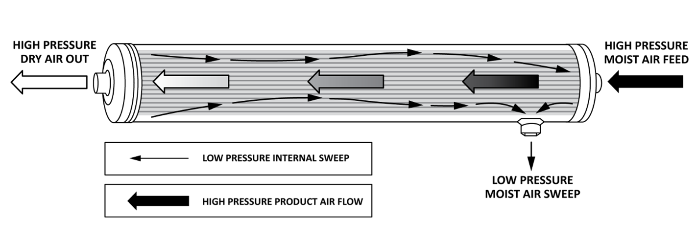
Figure 24 Cactus membrane dryer process
The membranes are highly susceptible to oil and dirt, which cause the membranes to break down quickly. As the structure is microscopic, it cannot be cleaned and has to be replaced.
Membrane dryers come in lightweight modular designs (Figure 25), which are easy to install, making them good for small to medium systems when space is at a premium or for mobile applications.
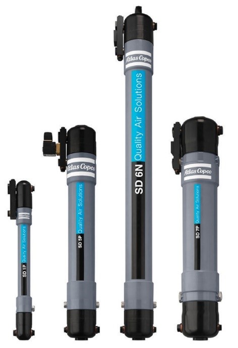
Figure 25 Selection of membrane dryers
Heat recovery equipment
As mentioned earlier, when air is compressed it gives off heat, and this heat must be removed to preserve system performance. Excess heat could be discarded as waste or recovered by transferring it to a cooling medium before the air goes out into the pipe system. As much as 90% of that heat can be recovered to create hot water for washrooms or warm air for a workspace.
An example of this is using a plate heat exchanger to capture heat from the compressor to heat process water in a plant. Double-wall heat exchangers provide additional protection against contamination, which in turn make them more suitable for heating applications in the food and pharmaceutical industries as well as for heating potable water. Some compressor manufacturers offer built-in heat recovery heat exchangers as options. In some cases, they are fully integrated inside the compressor cabinet and require very little on-site design. The heat recovery control unit shown in Figure 26 is for water-cooled, oil-free air compressors.
Figure 26 Heat recovery control unit for water-cooled oil-free air compressors
Demand Side Components
The demand side includes:
- distribution piping
- secondary receiver
- condensate drain trap configurations
- end-use equipment
Distribution piping
The air distribution piping links the various components of the compressed air system to deliver air to the points-of-use with minimal pressure loss. The specific configuration of a distribution system depends on the needs of the individual plant, but frequently consists of an extended network of main lines, branch lines, valves, and air hoses.
The main source of performance problems associated with industrial compressed air systems is often the piping layout. Most systems are usually one of two common types supplying design flow and pressure requirements:
- straight line networks
- closed loop networks
Straight line network
A straight network (Figure 27) maintains the pressure at the point of use by reducing the size of the central pipe as it moves away from the compressor. The problem with this design is that the flow rate must be sacrificed in order to preserve the downstream pressure. As a result, the equipment using the most air flow must be located nearest to the compressor. This generates production problems, as industrial processes are not necessarily designed this way. Although this system layout is comparatively inexpensive, is not the optimal network design.
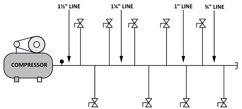
Figure 27 Straight line network
Over time, straight line networks often evolve into “octopus” networks (Figure 28). As new branch lines and equipment are added to an existing straight line network, the additional line and extension piping does not necessarily match the initial configuration. Air flow fluctuations caused by pneumatic equipment usage create problems maintaining pressure and flow requirements at the point of use. This type of network, while quite common, inherits all of the problems of the existing straight line network and makes them worse.
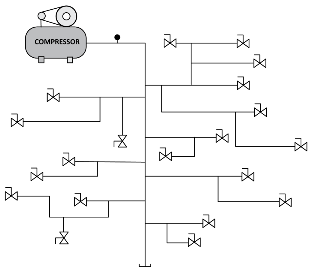
Figure 28 “Octopus” network
Closed-loop network
A properly designed distribution network should provide a balance between flow rate and pressure at all points of use in the system. The system should demonstrate flexibility during varying system demands and allow for future expansion. The best piping layout to achieve this performance is the closed-loop network design (Figure 29).
A closed-loop network allows the air supply to flow through several lines at a time with at least two different supply routes available simultaneously for each feeder pipe descending toward a tool or piece of equipment that could be located at any point in the system such as indicated by the letter “A” in the diagram.
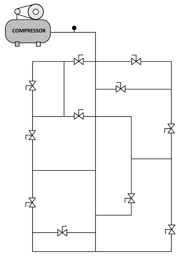
Figure 29 Closed-loop network
A well-built closed-loop network is therefore most often the ideal choice for the distribution of compressed air. In addition to being easy to plan and to modify when needed, this type of distribution system becomes an immense compressed air reservoir that:
- Offers a constant air flow at all times.
- Guarantees a uniform pressure throughout.
- Contributes to the life of the compressor by limiting functioning time.
- Reduces the electrical consumption of the compressor.
Secondary receivers
Some distribution systems provide additional receiver tanks in the process area. This creates an intermediate compressed air reservoir to dampen remote discharge pulsations in the system. These (usually smaller) air receiver tanks can be placed close to applications where there are requirements for relatively short, high air consumption events. So, instead of drawing from the primary storage and compressed air piping system to blast out a huge volume of air for only one short application, the secondary receiver acts as a system shock absorber and turns it into a continuous, smaller system demand.
Secondary receivers are also used to improve the performance of single line systems that have expanded beyond the original design or were a single main line has a considerable distance to travel.
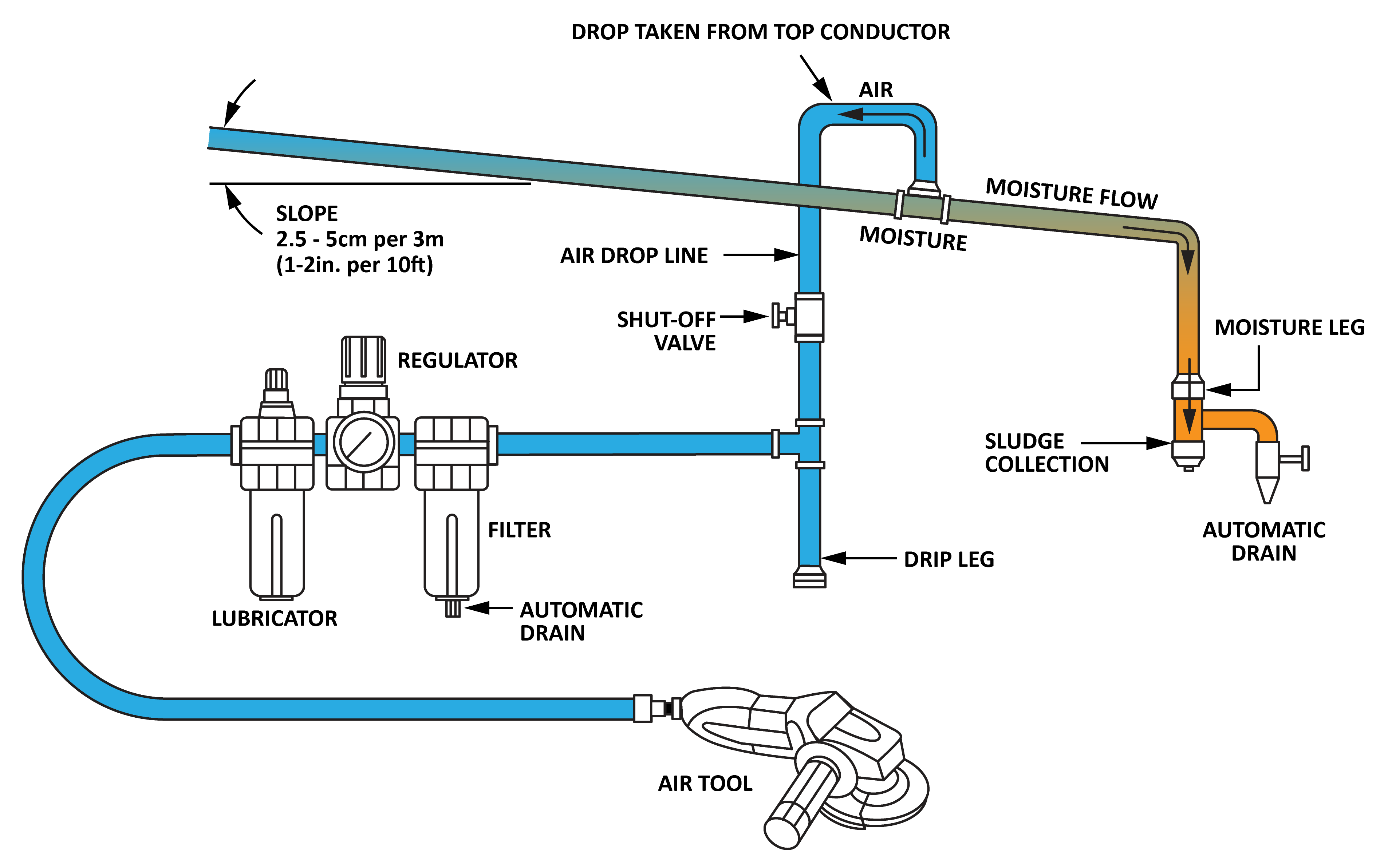
Draining of moisture
Atmospheric air always contains some water vapour. As the air is compressed, the water vapour is compressed along with it, and the increased pressure causes much of the water vapour in the air to condense and drop out in liquid form. When the distribution mains travel outside the compressor room, temperatures are typically lower, which promotes condensation. This water is harmful to the distribution system and the pneumatic equipment. In less-sophisticated systems, manual drains are used at system low points. They are essentially a ball or gate valve that is manually opened to drain the accumulated condensate. Because they depend on human interaction, they are either neglected or completely ignored. To eliminate this problem, a liquid drain trap is used to drain off the water while preventing the escape of compressed air.
Compressed air condensate drain traps automatically discharge moisture and oil from compressed air systems without the loss of any system air during the draining process. This feature is referred to as zero loss. Drain traps are installed throughout the system at locations that may include system low points, receiver tanks, intercoolers, aftercoolers, dryers, filters and drip legs. Unattended drain lines in the compressed air system can fill with liquid, flood the system and interfere with production equipment.
Modern compressed air drain equipment typically uses four main drain technologies:
- internal float drains
- pneumatic/mechanical drains
- timed solenoid electric drains
- electronic level-sensing drains
Internal float drains
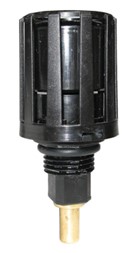
Internal float drains are typically located at the end-user filter housings and are available in normally open and normally closed configurations (Figure 30). The normally closed version is automatic; it operates when the float rises due to accumulated liquid, discharging condensate and debris from within the filter bowl. The normally open version is semi-automatic; it operates when the air-line is depressurized, for example at the end of a shift. When the system is pressurized, it will remain closed but the drain may be operated manually through an internal bypass.
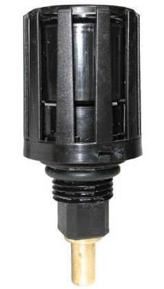
Figure 30 Internal float drain
Timed solenoid electric drains
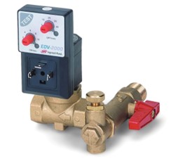
Timed solenoid electric drains operate by using two timers that a user can program according to their application and drain needs (Figure 31). One timer is set for the interval between each time the drain opens. The second timer is set for the amount of time that the drain is open. These drains are more resistant to clogging than internal float drains, although the orifice within the valve through which fluids flow is small, usually 3–5 mm (1/8″ to 3/16″). This orifice can plug up and should be protected with a y-strainer, which itself needs periodic cleaning. Timed solenoid drains are not a zero loss design as they also purge compressed air along with liquids.
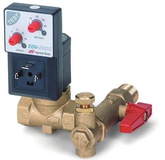
Figure 31 Series timed electric condensate drain
Electronic level-sensing condensate drain
Electronic level-sensing drains are a zero-loss design that operates based on the level of demand, not on a specific time setting where demand is not considered (Figure 32). This approach eliminates the biggest drawback to solenoid timer drains, which is the loss of compressed air. Level-sensing drains are called demand drains because they only activate when liquid is present.
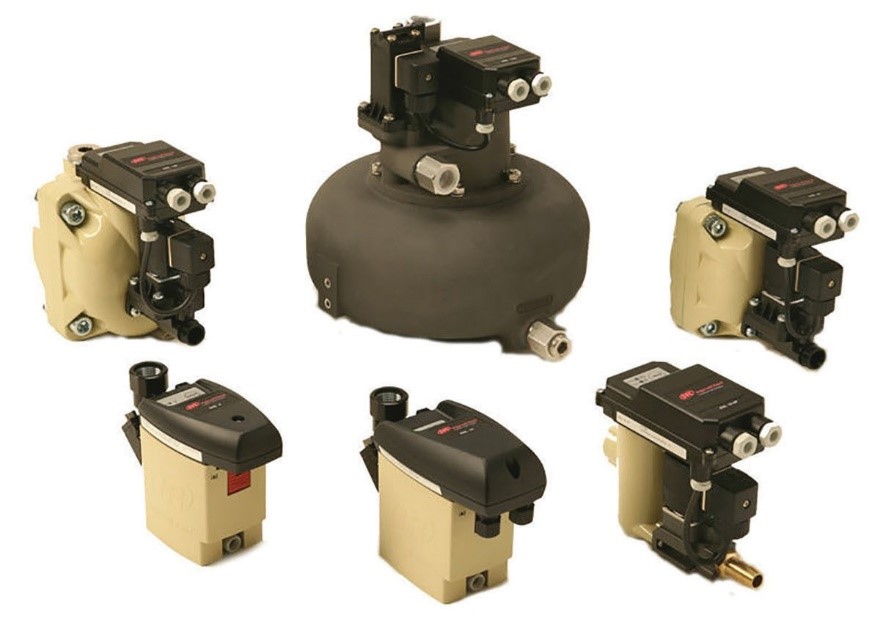
Figure 32 Electronic level-sensing condensate drains
Pneumatic/mechanical drains
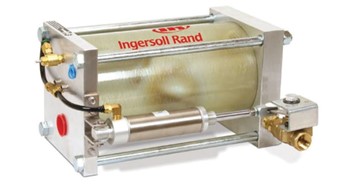
Pneumatic/mechanical drains are also a zero-loss design powered by air rather than electricity, so they are ideally suited for remote or portable applications (Figure 33). An external condensate reservoir collects liquid. When the liquid rises to a set point, a mechanical switch sends pilot air to an air cylinder that opens a ball valve, draining the reservoir. As the level of liquid in the reservoir drops, the mechanical switch closes, shutting off the pilot signal and closing the ball valve. No compressed air is wasted in the process, except for the tiny amount of pilot air. The ball valve has a straight-through flow pattern, so these drains are resistant to clogging and blockage.
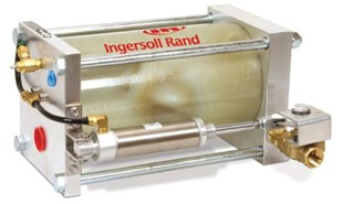
Figure 33 Pneumatic/mechanical condensate drain
End use equipment
Compressed air has many end use applications, including:
- Operating pneumatic cylinders or actuators
- Pneumatic hand tools
- HVAC control systems
- Air brakes
- Underwater diving
- Medical air
- Refilling portable compressed air tanks eg SCUBA or ammunition propulsion
- Sandblasting
- Spray painting
Tool and equipment performance depends on whether they receive the required rate of air flow. It is important to know whether the flow rate specified for a certain tool is stated in unpressurized terms (SCFM; standard cubic feet per minute) or in pressurized terms (CFM; cubic feet per minute), as there can be a great difference in the actual flow rate.
SCFM differs from CFM in that the “S” indicates that the air is “standardized” at 14.7 psia (103 kPa). SCFM establishes standard conditions used in the comparison of the air consumption of air tools and the output capacity of compressors. CFM, on the other hand, must be stated at a specified gauge pressure.
Secondary treatment
Secondary treatment of compressed air refers to the equipment outside of the supply side components. This can include additional filtration, pressure reduction, or lubrication. The final application will ultimately determine secondary treatment that will be installed to ensure the necessary quality of compressed air that is required. For example one installation may be using equipment that requires oil lubrication for air tools; then an automatic line lubricator should be installed. In another case, where paint spraying is done, a lubricator would create a problem.
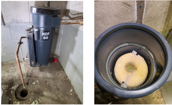
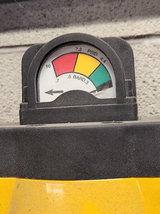
Filters need to be serviced regularly; cartridges need to be cleaned or replaced depending on the manufacturers instructions. Some filters come with differential pressure indicating gauges (Figure 34). Pressure drop is determined by measuring the difference between the inlet and the outlet pressures of a filter element. Once the pressure drop reaches 10psi, the element is starting to become clogged, which can begin to adversely affect system performance.
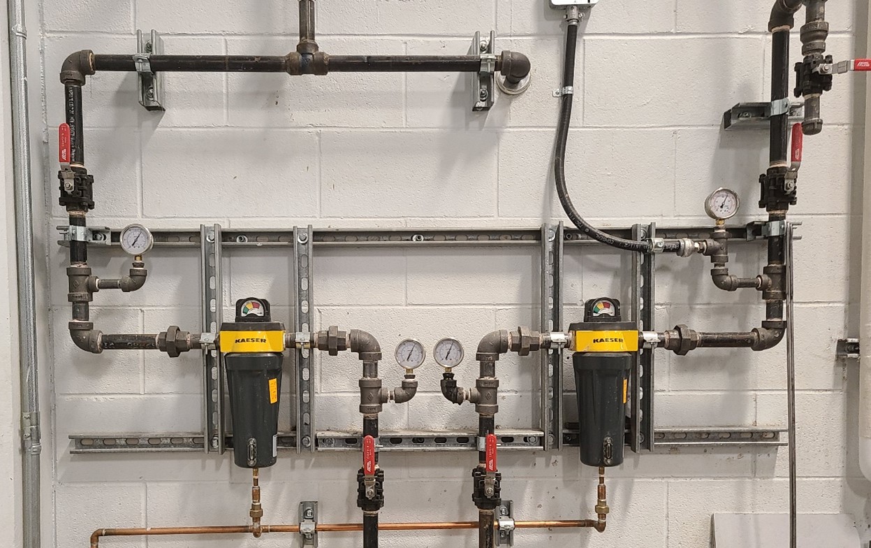
Figure 34 Secondary filter bank
Filter regulator lubricator devices (FRL)
Before air can be used to drive tools and equipment it needs to be filtered, regulated and lubricated. In many cases these air treatments are provided at the connection point with an assembly called a filter, regulator, lubricator (FRL) (Figure 35).
- Filters: These purify the air by filtering out moisture and other impurities.
- Regulators: Pneumatic equipment must operate at the pressure for which it was designed or equipment damage may occur. Regulators are designed to provide constant pressure to ensure that an established pressure is not exceeded.
- Lubricators: Many pneumatic applications require an air supply that contains a lubricant. Lightly lubricating a tool’s moving parts allows the tool to perform at optimal levels and increases its lifespan.
The FRL unit must be installed in the air line in the correct position in order to prevent contaminant damage. If an FRL is installed backwards, the oil from the lubricator will gum up the regulator and the filter.
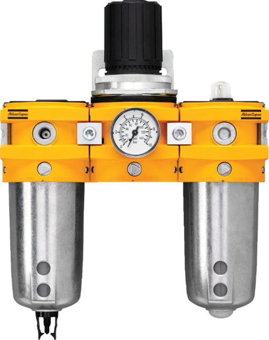
Figure 35 Filter, regulator, lubricator (FLR)
Safety Devices
Every air compressor is fitted with safety features to avoid abnormal and dangerous operational errors of the equipment. If safety alarms and trips are not present on the air compressor, abnormal operation may lead to breakdown of the compressor and may also injure a person working on or around it. Depending on the size and application, an air compressor may have any or all of the following devices.
Pressure relief valve (PRV)
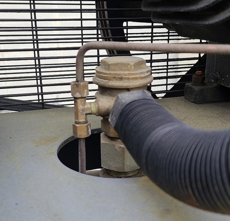
When the pressure inside the system reaches the PRV set point, the air pressure acting on the piston inside the PRV overcomes the spring pressure, forcing the piston out and opening the flow path from the air line or tank to atmosphere, venting excess pressure. Once the over- pressure condition has been reduced below the PRV set point, the valve re-seats and returns to service (Figure 36).
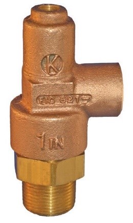
Figure 36 Pressure relief valve
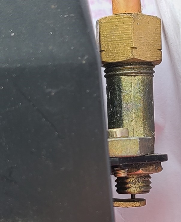
Bursting disk
Also known as a rupture disk, this is an “engineered weak spot” within a pressurized system that is designed to burst at a predetermined pressure (Figure 37). It is a one-time device used to protect a system from overpressure damage.
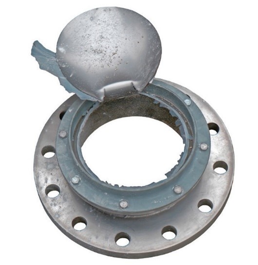
Figure 37 Bursting disk
Fusible plug
Generally located on the discharge side of the compressor, this is a single-use device that operates as a safety valve in response to dangerous temperatures, rather than dangerous pressures. A tapered hole is drilled completely through its length and sealed with a metal of low melting point that flows away if a predetermined high temperature is reached.
Safety alarm systems
Many large industrial applications have specialty alarm systems interlocked into the control system. A safety shutdown of the system will occur under any of the following events:
- Low oil pressure
- Water high temperature
- Water no-flow
- Motor overload
Low oil pressure alarm and trip: If the lubricating oil pressure falls below normal, an alarm sounds, followed by a cut-out or “trip” signal that shuts off power to the compressor to avoid damage to the bearings and crankshaft.
Water high temperature trip: If the intercoolers are choked or the flow of water is restricted, the air compressor will overheat. To avoid this situation, a high water temperature trip is activated that shuts off the compressor.
Water no-flow trip: If the attached pump is not working or the flow of water inside the intercooler is insufficient to cool the compressor, then moving parts inside the compressor will overheat and seize. A no-flow trip is provided to continuously monitor the flow of water and trips the compressor when there is no flow.
Motor overload trip: If the current to the motor during running or starting is very high, the motor may sustain damage. An overload trip will avoid such a situation.
Now complete Self-Test 1 and check your answers.
Image Attributions
- Figure 1 Basic Compressed Air System by Rod Lidstone, adapted from “Basic Compressed Air System” by ITA, is licensed under a CC BY 4.0 licence.
- Figure 2 Supply Side Components by Camosun College is licensed under a CC BY 4.0 licence.
- Figure 3 Single-stage reciprocating single acting air compressor by Camosun College is licensed under a CC BY 4.0 licence.
- Figure 4 Two-stage reciprocating single acting air compressor by ITA is licensed under a CC BY-NC-SA licence.
- Figure 5 Single-stage reciprocating double acting air compressor by Camosun College is licensed under a CC BY 4.0 licence.
- Figure 6 Reciprocating diaphragm single acting air compressor by Camosun College is licensed under a CC BY 4.0 licence.
- Figure 7 Dual and single stage rocking piston air compressors by ITA is licensed under a CC BY-NC-SA licence.
- Figure 8 Rotary sliding vane compressor by Camosun College is licensed under a CC BY 4.0 licence.
- Figure 9 Compression in a twin-screw compressor by Camosun College is licensed under a CC BY 4.0 licence.
- Figure 10 Oil injected rotary screw compressor by Camosun College is licensed under a CC BY 4.0 licence.
- Figure 11 Oil-free screw compressor with synchronizing helical screws to maintain very small rotor clearances by Camosun College is licensed under a CC BY 4.0 licence.
- Figure 12 Rotary scroll compressor cross section by Camosun College is licensed under a CC BY 4.0 licence.
- Figure 13 Three-stage compressor with twin intercoolers by Camosun College is licensed under a CC BY 4.0 licence.
- Figure 14 Air-cooled aftercooler Water cooled after cooler by ITA is licensed under a CC BY-NC-SA licence.
- Figure 15 Air compressor intake filter by ITA is licensed under a CC BY-NC-SA licence.
- Figure 16 Centrifugal separator by Camosun College is licensed under a CC BY 4.0 licence.
- Figure 17 Coalescing separator by Camosun College is licensed under a CC BY 4.0 licence.
- Figure 18 Oil/water condensate separator by ITA is licensed under a CC BY-NC-SA licence.
- Figure 19 High-pressure air receiver by ITA is licensed under a CC BY-NC-SA licence.
- Figure 20 Refrigerant air dryer by ITA is licensed under a CC BY-NC-SA licence.
- Figure 21 Deliquescent air dryer by ITA is licensed under a CC BY-NC-SA licence.
- Figure 22 Desiccant air dryer by ITA is licensed under a CC BY-NC-SA licence.
- Figure 23 Membrane dryer microtubes by ITA is licensed under a CC BY-NC-SA licence.
- Figure 24 Cactus membrane dryer process by Camosun College is licensed under a CC BY 4.0 licence.
- Figure 25 Selection of membrane dryers by ITA is licensed under a CC BY-NC-SA licence.
- Figure 26 Heat recovery control unit for water-cooled oil-free air compressors by ITA is licensed under a CC BY-NC-SA licence.
- Figure 27 Straight line network by Camosun College is licensed under a CC BY 4.0 licence.
- Figure 28 “Octopus” network by Camosun College is licensed under a CC BY 4.0 licence.
- Figure 29 Closed-loop network by Camosun College is licensed under a CC BY 4.0 licence.
- Figure 30 Internal float drain by ITA is licensed under a CC BY-NC-SA licence.
- Figure 31 Series timed electric condensate drain by ITA is licensed under a CC BY-NC-SA licence.
- Figure 32 Electronic level-sensing condensate drains by ITA is licensed under a CC BY-NC-SA licence.
- Figure 33 Pneumatic/mechanical condensate drain by ITA is licensed under a CC BY-NC-SA licence.
- Figure 34 Secondary filter bank by Rod Lidstone, Camosun College is licensed under a CC BY 4.0 licence.
- Figure 35 Filter, regulator, lubricator (FLR) by ITA is licensed under a CC BY-NC-SA licence.
- Figure 36 Pressure relief valve by ITA is licensed under a CC BY-NC-SA licence.
- Figure 37 Bursting disk by ITA is licensed under a CC BY-NC-SA licence.


 Do not place your bare skin too close to a compressed air leak.