An orifice is a hole or opening used primarily in the gas industry to control the direction and amount of gas that is discharged into a burner.
Changing input to the burner can only be accomplished by adjusting the manifold pressure or by changing the area of the orifice.
A gas orifice is a simple device that comes in a variety of shapes and forms.
Orifices discussed in this section fall into two categories; main burner orifices and pilot orifices.
Main Burner Orifices
Main burner orifices come in three common types, each having particular characteristics:
- Fixed (Plug)
- Cap (Universal)
- Adjustable
Fixed orifices
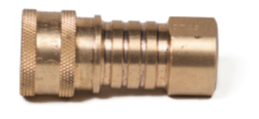
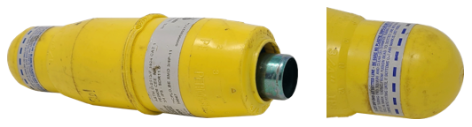
Fixed orifices, also known as orifice spuds, are the most common orifice type and are simply a drilled opening in a brass or aluminium orifice spud. The orifice spud comes with a male thread which allows it to be screwed into the manifold of the burner assembly (Figure 1).
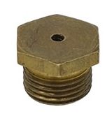
Figure 1 Orifice Spud
Cap (universal) orifices
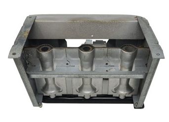
Cap or universal orifices are found on dual fuel appliances designed to be operated on natural gas or propane without replacing the orifices (Figure 2).
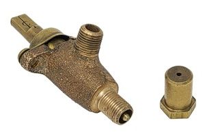
Figure 2 Gas range Cap orifice
Under the cap (or hood) of the orifice is a needle with a hole drilled through it which is sized for the propane use. For propane operation, which has a higher heat value, the cap is threaded onto the needle (clockwise), giving a fixed flow rate through the needle hole. (Figure 3)
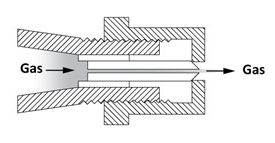
Figure 3 Cap orifice setup for propane
For natural gas use, having a lower heat value, a greater flow rate is required so the orifice cap or hood is unthreaded (counter-clockwise) away from the needle. This allows the gas to also flow both through around the needle opening and around the opening between the shoulder and the edge of the orifice in the hood (Figure 4). For the most part the opening size in the hood becomes the fixed orifice for the required natural gas flow rate, but some flow rate adjustment is available by fine tuning the amount of gas that can squeeze through the area between the needle shoulder and the edge of the cap hole.
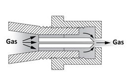
Figure 4 Cap orifice setup for natural gas
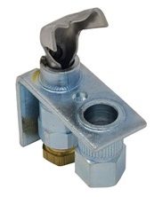
Adjustable orifices
Adjustable orifices are used on some nozzle-mix and pre-mix industrial burners. The needle inside the orifice spud is adjustable to increase or decrease the effective opening of the orifice. The gas flow rate can be altered from zero, with the needle tight against the orifice wall, or to the full flow rate, with the needle backed away from the orifice wall (Figure 5).
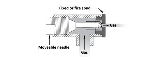
Figure 5 Adjustable orifice
Pilot Orifices
As the flame is very small for a pilot burner, the pilot burner orifice opening will be smaller than the main burner orifice. They come in two common designs types to accommodate their mounting to the pilot burner:
Spud type
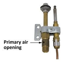
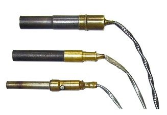
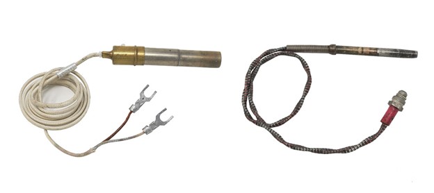
The spud type orifice will have a threaded or flare gas supply connection on its inlet end as well as threaded seat on the orifice end (Figure 6). This short straight thread is used to secure the spud to the pilot burner assembly.
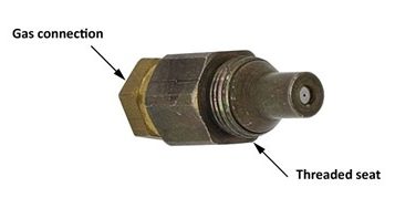
Figure 6 Spud type pilot orifice
Insert type
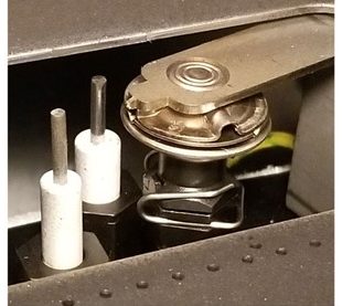
The insert type of pilot orifice has no threaded seat or gas connection. It is an aluminum cone shaped insert that sits in a receptacle on the burner assembly (Figure 7). It gets held in place and sealed by the pilot tubing inlet fitting.
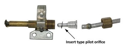
Figure 7 Insert type pilot orifice
The volume of gas (flow rate) that passes through an orifice can be expressed as ft3/hr or m3/hr of flow and the input as Btu/h or kW.
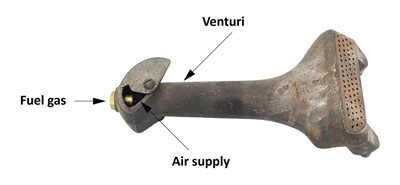
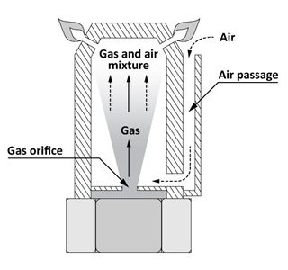
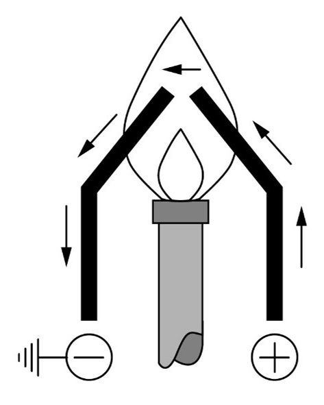
Before examining the sizing of gas orifices, you must be familiar with the following four factors that influence the flow of gas through an orifice (Figure 8).
- K factor
- Pressure drop
- Specific gravity
- Area
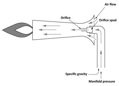
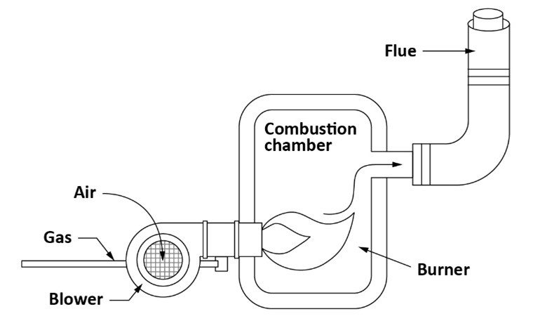
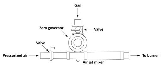
Figure 8 Burner showing gas flow through an orifice
K Factor
The orifice coefficient of flow factor (K factor) is determined by the angle of approach to the orifice and by the orifice design. If the angle of approach is altered by drilling, or by changing the orifice type, the K factor will change. This helps explain why drilling out an orifice doesn’t always get the exact flow result you may expect. This K-factor alteration is the reason that some manufactures will specify that you cannot drill out the orifices when doing a fuel conversion.
Pressure Drop
The pressure drop across an orifice is determined by the manifold pressure of the appliance. It is normally the difference between the manifold pressure and the atmospheric pressure surrounding the orifice outlet. Altering the manifold pressure will change the flow rate through the orifice. Flow rate (Q) increases with the square root of the pressure increase.

Many modern appliances have sealed combustion chambers and the pressure surrounding the orifice outlet can fluctuate, therefore the appliance will have a means to automatically alter the manifold pressure to maintain a constant pressure differential across the orifice. Also, appliances with modulating burners will automatically change the manifold pressure for the purpose of turning down the burner input to match the heat demand.
As was discussed in E5 LT2 it is also worth mentioning that, for atmospheric burners, different manifold pressures are used for different gasses to alter the venturi effect and change the primary air proportion.
Additionally, some burners, that do not rely on primary air pre-mix, may operate on manifold pressures as low as 1″ WC.
Specific Gravity
As we know all gasses have a different density and these are expressed as their specific gravity (Sg) or relative density compared to air. The Sg of natural gas is usually taken as 0.6, propane as 1.5, and butane as 2.0. It stands to reason that a heavier gas will flow less easily through an orifice.
This change in flow rate (Q) can be predicted as it varies inversely to the square root of the Sg of the gas.

In fact, you may have seen some conversion constants used in Table A.15 of the B149 Gas Code for converting the flow rates of the gas pipe sizing tables for alternate gases, these were calculated with this formula.
Area
You can change the flow rate to the burner by resizing the orifice. The flow rate or orifice capacity varies in direct proportion to the orifice’s area measurement.

Drill size
In the gas industry, there are four measuring systems used to indicate the size (diameter) of the orifice, these are based on the drill bit used when the orifice was drilled.
- Drill manufacturers size (DMS)
- Letter size
- Fractional size
- Metric size
Drill manufacturer’s size
This is a series of numbered drill bits ranging from the smallest at No. 80 (0.0135 in.) to the largest at No. 1 (0.2280 in.). An example of a common drill index is shown in Figure 9 includes twist drills from #1 through #40, smaller sizes are too delicate to be used in a power drill.
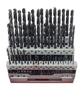
Figure 9 Twist drill index
The orifice drill set in Figure 10 contains the smaller sizes from #40 through #80 and is designed to be used by finger twisting.
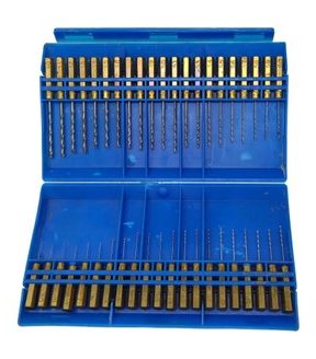
Figure 10 Finger orifice drill set
Letter drill size
This series has letter size drill bits ranging from the smallest at “A” (0.2350 in.) to the largest at “Z” (0.4130 in.).
Fractional drill size
This series of drill bits range from  inch to 1 inch and are expressed in of an inch increments. Bigger drill sizes are available although the unit of increment is larger.
Metric drill size
These drill bit sizes have their diameters expressed in millimetres. The sizing starts at 0.25 mm and increases by 0.05 mm increments.
The flowing table will help correlate the four different drill size systems, as it arranges them in ascending order of size with there equivalent decimal inches diameter.
Drill
Size | Decimal
Inches | Drill
Size | Decimal
Inches | Drill
Size | Decimal
Inches | Drill
Size | Decimal
Inches | Drill
Size | Decimal
Inches |
|---|
| 0.25 mm 0.30 mm #80 0.35 mm #79 | 0.0098 0.0118 0.0135 0.0138 0.0145 | #50 1.80 mm 1.85 mm #49 1.90 mm | 0.0700 0.0709 0.0730 0.0730 0.0748 | 3.90 mm #23 5/32″ #22 4.00 mm | 0.1535 0.1540 0.1562 0.1570 0.1575 | 6.70 mm 17/64″ H 6.80 mm 6.90 mm | 0.2638 0.2656 0.2660 0.2677 0.2716 | 10.40 mm Z 10.50 mm 10.60 mm 10.70 mm | 0.4094 0.4130 0.4134 0.4173 0.4213 |
| 1/64″ 0.40 mm #78 0.45 mm #77 | 0.0156 0.0157 0.0160 0.0177 0.0180 | #48 1.95 mm 5/64″ #47 2.00 mm | 0.0760 0.0768 0.0781 0.0785 0.0787 | #21 #20 4.10 mm 4.20 mm #19 | 0.1590 0.1610 0.1614 0.1654 0.1660 | I 7.00 mm J 7.10 mm K | 0.2720 0.2756 0.2770 0.2795 0.2811 | 27/64″ 10.80 mm 10.90 mm 11.00 mm 11.10 mm | 0.4219 0.4252 0.4291 0.4330 0.4370 |
| 0.50 mm #76 #75 0.55 mm #74 | 0.0197 0.0200 0.0210 0.0217 0.0225 | 2.05 mm #46 #45 2.10 mm 2.15 mm | 0.0807 0.0810 0.0820 0.0827 0.0846 | 4.30 mm #18 11/64″ #17 4.40 mm | 0.1693 0.1695 0.1719 0.1730 0.1732 | 9/32″ 7.20 mm 7.30 mm L 7.40 mm | 0.2811 0.2835 0.2874 0.2900 0.2913 | 7/16″ 11.20 mm 11.30 mm 11.40 mm 11.50 mm | 0.4375 0.4409 0.4449 0.4488 0.4528 |
| 0.60 mm #73 #72 0.65 mm #71 | 0.0236 0.0240 0.0250 0.0256 0.0260 | #44 2.20 mm 2.25 mm #43 2.30 mm | 0.0860 0.0866 0.0886 0.0890 0.0905 | #16 4.50 mm #15 4.60 mm #14 | 0.1770 0.1771 0.1800 0.1811 0.1820 | M 7.50 mm 19/64″ 7.60 mm N | 0.2950 0.2953 0.2968 0.2992 0.3020 | 29/64″ 11.60 mm 11.70 mm 11.80 mm 11.90 mm | 0.4531 0.4567 0.4606 0.4646 0.4685 |
| 0.70 mm #70 #69 0.75 mm #68 | 0.0276 0.0280 0.0292 0.0295 0.0310 | 2.35 mm #42 3/32″ 2.40 mm #41 | 0.0925 0.0935 0.0937 0.0945 0.0960 | 4.70 mm #13 3/16″ 4.80 mm #12 | 0.1850 0.1850 0.1875 0.1890 0.1890 | 7.70 mm 7.80 mm 7.90 mm 5/16″ 8.00 mm | 0.3031 0.3071 0.3110 0.3125 0.3150 | 15/32″ 12.00 mm 12.10 mm 12.20 mm 12.30 mm | 0.4687 0.4724 0.4764 0.4803 0.4843 |
| 1/32″ 0.80 mm #67 #66 0.85 mm | 0.0313 0.0315 0.0320 0.0330 0.0335 | 2.45 mm #40 2.50 mm #39 2.55 mm | 0.0965 0.0980 0.0984 0.0995 0.1004 | #11 4.90 mm #10 #9 5.00 mm | 0.1910 0.1929 0.1935 0.1960 0.1968 | O 8.10 mm 8.20 mm P 8.30 mm | 0.3160 0.3189 0.3228 0.3230 0.3268 | 31/64″ 12.40 mm 12.50 mm 12.60 mm 12.70 mm | 0.4843 0.4882 0.4921 0.4961 0.5000 |
| #65 0.90 mm #64 #63 0.95mm | 0.0350 0.0354 0.0360 0.0370 0.0374 | #38 2.60 mm #37 2.65 mm 2.70 mm | 0.1015 0.1024 0.1040 0.1043 0.1063 | #8 5.10 mm #7 13/64″ #6 | 0.1990 0.2008 0.2010 0.2031 0.2040 | 21/64″ 8.40 mm Q 8.50 mm 8.60 mm | 0.3281 0.3307 0.3320 0.3346 0.3386 | 1/2″ 12.80 mm 12.90 mm 13.00 mm 33/64″ | 0.5000 0.5039 0.5079 0.5118 0.5156 |
| #62 #61 1.00 mm #60 #59 | 0.0380 0.0390 0.0394 0.0400 0.0410 | #36 2.75 mm 7/64″ #35 2.80 mm | 0.1065 0.1083 0.1093 0.1100 0.1102 | 5.20 mm #5 5.30 mm #4 5.40 mm | 0.2047 0.2055 0.2087 0.2090 0.2126 | R 8.70 mm 11/32″ 8.80 mm S | 0.3390 0.3425 0.3437 0.3465 0.3480 | 13.10 mm 13.20 mm 13.30 mm 13.40 mm 17/32″ | 0.5157 0.5197 0.5236 0.5276 0.5313 |
| 1.05 mm #58 #57 1.10 mm 1.15 mm | 0.0413 0.0420 0.0430 0.0433 0.0453 | #34 2.85 mm #33 2.90 mm #32 | 0.1110 0.1122 0.1130 0.1142 0.1160 | #3 5.50 mm 7/32″ 5.60 mm #2 | 0.2130 0.2165 0.2187 0.2205 0.2210 | 8.90 mm 9.00 mm T 9.10 mm 23/64″ | 0.3504 0.3543 0.3580 0.3583 0.3594 | 13.50 mm 13.60 mm 13.70 mm 13.80 mm 35/64″ | 0.5315 0.5354 0.5394 0.5433 0.5469 |
| #56 3/64″ 1.20 mm 1.25 mm 1.30 mm | 0.0465 0.0469 0.0472 0.0492 0.0512 | 2.95 mm 3.00 mm #31 3.10 mm 1/8″ | 0.1161 0.1181 0.1200 0.1220 0.1250 | 5.70 mm #1 5.80 mm 5.90 mm A | 0.2244 0.2280 0.2283 0.2323 0.2340 | 9.20 mm 9.30 mm U 9.40 mm 9.50 mm | 0.3622 0.3661 0.3680 0.3701 0.3740 | 14.00 mm 14.25 mm 9/16″ 14.50 mm 37/64″ | 0.5512 0.5610 0.5625 0.5709 0.5781 |
| #55 1.35 mm 1.40 mm #54 1.45 mm | 0.0520 0.0531 0.0550 0.0550 0.0571 | 3.20 mm #30 3.30 mm 3.40 mm #29 | 0.1260 0.1285 0.1299 0.1339 0.1360 | 15/64″ 6.00 mm B 6.10 mm C | 0.2344 0.2362 0.2380 0.2401 0.2420 | 3/8″ V 9.60 mm 9.70 mm 9.80 mm | 0.3750 0.3770 0.3780 0.3819 0.3858 | 15.50 mm 15.75 mm 5/8″ 16.00 mm 16.25 mm | 0.6102 0.6201 0.6250 0.6299 0.6398 |
| 1.50 mm #53 1.55 mm 1/16″ 1.60 mm | 0.0591 0.0595 0.0610 0.0625 0.0629 | 3.50 mm #28 9/64″ 3.60 mm #27 | 0.1378 0.1405 0.1405 0.1417 0.1440 | 6.20 mm D 6.30 mm E 1/4″ | 0.2441 0.2460 0.2480 0.2500 0.2500 | W 9.90 mm 25/64″ 10.00 mm X | 0.3860 0.3898 0.3906 0.3937 0.3970 | 47/64″ 18.75 mm 19.00 mm 3/4″ 19.25 mm | 0.7344 0.7382 0.7480 0.7500 0.7579 |
| #52 1.65 mm 1.70 mm #51 1.75 mm | 0.0635 0.0650 0.0669 0.0670 0.0689 | 3.70 mm #26 #25 3.80 mm #24 | 0.1457 0.1470 0.1495 0.1496 0.1520 | 6.40 mm 6.50 mm F 6.60 mm G | 0.2520 0.2559 0.2570 0.2598 0.2610 | 10.10 mm 10.20 mm Y 10.30 mm 13/32″ | 0.3976 0.4016 0.4040 0.4055 0.4062 | 31/32″ 24.75 mm 25.00 mm 63/64″ 1″ | 0.9688 0.9744 0.9843 0.9844 1.0000 |
Orifice Sizing Methods
There are two methods of determining the correct orifice size:
- the orifice flow formula
- the orifice capacity tables
Orifice flow formula
The orifice flow formula shown below, gives the relationship between the gas flow through the orifice and the pressure drop across the orifice, the area of the orifice, and the specific gravity of the gas.

| Q | the flow rate of gas in cubic feet per hour |
|---|
| 1,658.5 | a constant used to convert the units of measure for area and pressure to cubic feet per hour |
|---|
| K | coefficient of flow factor that considers the efficiency of the orifice (usually approximately 0.9 for domestic gas burners) |
|---|
| A | cross sectional area of the orifice in square inches |
|---|
| ΔP | the pressure difference or pressure drop across the orifice expressed in inches of water column |
|---|
| Sg | the specific gravity of the fuel gas being used |
|---|
This flow formula is only used for low pressure gas applications, making it appropriate for gas appliance orifices.
The formula could be used as shown above to determine the flow rate through a given orifice size, but more often you are trying to determine the required orifice for a given appliance input. In that case the formula could be reorganized to read:

Here is an example of using the formula to determine the orifice sizes for a 100 MBH appliance with 4 burners operating on natural gas (Sg 0.6) at a manifold pressure of 4 inches of water column using orifice with a 0.9 K factor.
- The first step is to determine the flow rate per orifice in ft3/hr for each orifice:
}}{\small\text{Number of orifices}} \div \text{calorific value of the gas (Btu/}{ft}^{3}) \\ \text{Flow rate per orifice} = \dfrac{100,000 Btuh}{4 \text{ burners}} \div 1000 { Btu/ft}^{3} \\ \text{Flow rate per orifice (Q)} = 25 { ft}^{3}/hr \end{array}")
- Now you can calculate the orifice area:

- You will need to convert the orifice area into a diameter to get the actual drill size:
} = \sqrt{\dfrac{A}{.7854}} \\ D = \sqrt{\dfrac{.0065 { \text{in}}^{2}}{.7854}} \\ D = .0909 \text{ in }\end{array}")
- When we check the drill size cross index chart we find that an orifice with a diameter of .0909 in. falls between:
- 2.30 mm = .0905 in.
- 2.45 mm = .0925 in.
If you were selecting one you would always choose the smaller orifice so that the appliance is not overfired. Therefore the 2.30 mm would be the correct orifice size. If number drill sizes were our only choice then you would go down to a No. 43 having an area of 0.0890 in.
Orifice capacity tables
The orifice capacity tables have been created from the orifice flow formula for a more convenience method of orifice sizing. There are a variety of orifice flow tables available so you must select a table that matches the type of gas being used, identified by its Sg. The K factor, or coefficient of discharge, should also be shown on orifice capacity table, the K-factor used by the table should match the K-factor of the orifice. If the K-factor of the orifice is not known, use 0.9 for commercial and residential equipment.
One example of an orifice capacity table can be found in the CSA B149.1 Natural gas and propane installation code, in Annex I, Table I.3. If you look at that table you will notice the following flow factors that were used in the creation of this table:
- Three different fuel gas options;
- Propane with a gross calorific value (CV) of 2520 and Sg of 1.52,
- Butane, with a CV of 3260 and Sg of 2.00,
- Natural gas with a CV of 1000 and Sg of 0.55
- Orifice K factors – 0.8 and 0.779
- Manifold pressure; Propane and Butane 11 in w.c., Natural gas 3.5
- The flow values per orifice are expressed in Btuh and kW
If any of these factors are different on the actual appliance being used then adjustments will need to be made to the flow values shown in the table to be completely accurate.
As with the flow formula there are some initial steps required to calculate the flow value required for each orifice from the appliance input rating. As there are a variety of orifice tables available the orifice flow values could be expressed as:
- Heat input per orifice (Btuh, or kW)
- Flow Rate per orifice (ft3/hr, or m3/hr)
If the table being used expresses the orifice flow values as a heat input then:
- Heat Input = Input of Appliance (Btuh or kW) ÷ Number of burners
If the table being used expresses the orifice flow values as a flow rate then:
Here are some examples using the Table I.3 in the CSA B149.1 Natural gas and propane installation code.
A boiler is to be fired on natural gas having a calorific value of 1,000 Btu/Ft.3. The appliance rating plate lists an input of 90,000 Btuh and a manifold pressure of 3.5 inches water column. The boiler has three burners.
Determine the orifice sizes:
- Select an orifice capacity table matching; Gas. CV, Sg, manifold pressure and orifice K-factor. For this example we will say that our orifices are 0.779 K-factor to match the code book
- From the table confirm the orifice flow value that is used. In this case the table expresses the flow values as heat input per orifice (Btuh and kW)
- Calculate the heat input per orifice.
- Heat Input = Input of Appliance (Btuh or kW) ÷ Number of burners
- Heat Input per orifice = 90,000 Btuh ÷ 3 burners
- Heat Input per orifice = 30,000 Btuh
- Follow down appropriate (Natural gas ) column until a heat input (equal to or less than) the required 30,000 Btuh is found (Figure 11).
- The closest value that is equal to or less than 30,000 is 29,138. Looking directly to the far left of that row the orifice size would be No. 36, this is the largest orifice size that can be installed without overfiring the appliance.
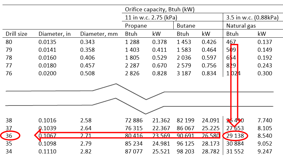
Figure 11 Example 1 excerpt from Natural gas and propane installation code
If the same (90,000 Btuh ) boiler in the previous example is being converted for the use of propane gas having a calorific value of 2,500 Btu/Ft.3 and a manifold pressure of 11 inches water column. The boiler has three burners. Determine the orifice sizes:
- Select an orifice capacity table matching; Gas. CV, manifold pressure and orifice K-factor. For this example, we will say that our orifices are 0.8 K-factor to match the code book.
You will notice the gas code tables use a propane gas with a slightly higher Sg and heat value, this minor difference will not affect our selection but we will look at how to adjust table values when the difference is mote significant in later examples. - From the table confirm the orifice flow value that is used. In this case Table I.3 (Figure 12) expresses the flow values as heat input per orifice (Btuh and kW)
- Calculate the heat input per orifice.
- Heat Input = Input of Appliance (Btuh or kW) ÷ Number of burners
- Heat Input per orifice = 90,000 Btuh ÷ 3 burners
- Heat Input per orifice = 30,000 Btuh
- Follow down the appropriate (Propane gas) column until a heat input (equal to or less than) the required 30,000 Btuh is found.
- The closest value that is equal to or less than 30,000 is 28,383. Looking directly to the far left of that row the orifice size would be No. 52, this is the largest orifice size that can be installed without overfiring the appliance using propane gas.
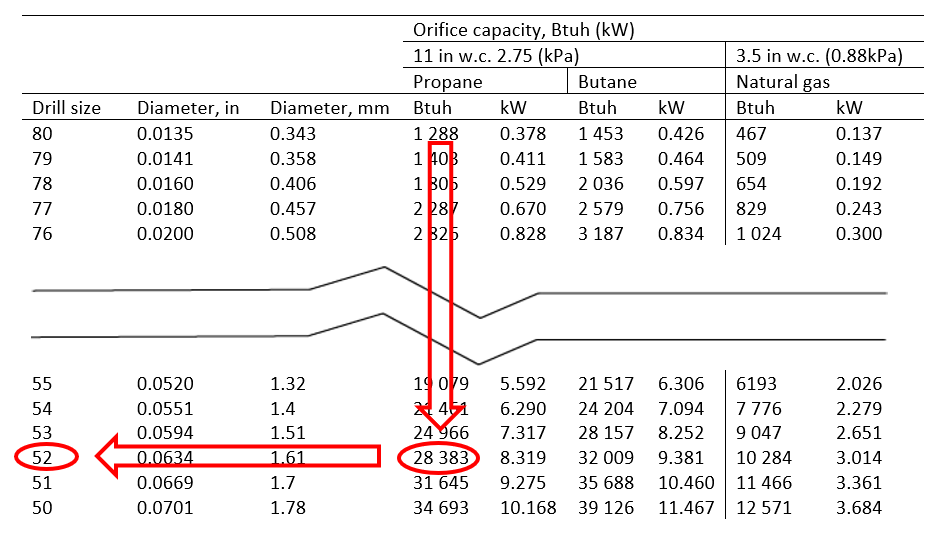
Figure 12 Example 2 excerpt from Natural gas and propane installation code
Alternate tables to the Code book
The previous examples were designed to match the specific flow factors in Table 1.3 of the Gas code. There are many other orifice sizing tables available from other sources such as; manufacturers, internet, spread sheets or even phone apps. If you were to search the internet for “Gas Orifice Capacity Chart” you would find that most of the tables will have more than one choice of manifold pressure, as not all domestic and commercial appliances are designed to operate at the limited choices of pressures that are available in Table I.3.
If you find differences between two tables it is likely that they were created using slightly different flow factors such as the Sg or K-factor. To be completely accurate correction calculations can be made to adjust the flow values shown in the tables.
The orifice capacity table included as Appendix 2 at the end of this book has additional choices for manifold pressures and will be used for the following examples and self test questions.
A forced warm air furnace is to be fired on natural gas having a calorific value of 1,000 Btu/Ft.3 and an Sg of 0.60. The appliance rating plate lists an input of 100,000 Btuh and a manifold pressure of 4.0 inches water column. The furnace has four burners.
Determine the orifice sizes:
- From the table confirm the orifice flow value that is used. In this case the table expresses the flow values as flow rate per orifice in CFH (ft3/hr)
- Calculate the flow rate per orifice.
- Calculate the flow rate per orifice.
- Follow down appropriate (Natural gas) manifold pressure column of 4.0″ WC (Figure 13) until a flow rate (equal to or less than) the required 25 CFH is found.
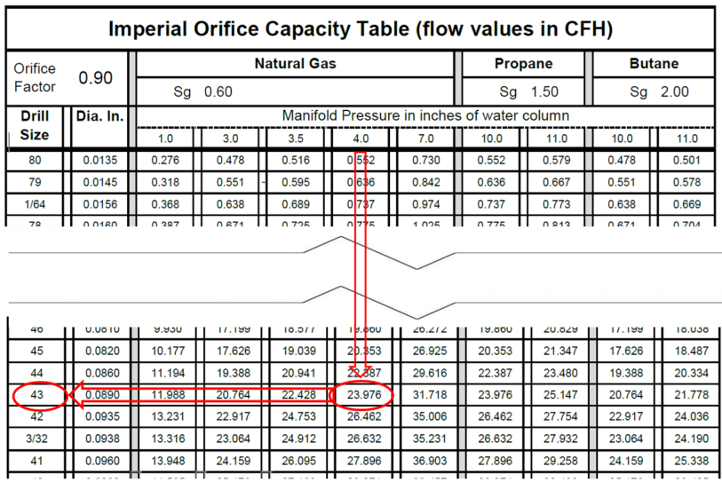
Figure 13 excerpt from Appendix 2 Table
- The closest value that is equal to or less than 25 CFH is 23.976. Looking directly to the far left of that row the orifice size would be No. 43, this is the largest orifice size that can be installed without overfiring the appliance.
If the same (100,000 Btuh ) furnace from the previous example 3 is being converted for the use of butane gas having a calorific value of 3200 Btu/Ft.3 , and Sg of 2.00, and a manifold pressure of 10 inches water column. The furnace has three burners. Determine the orifice sizes:
- Select an orifice capacity table with matching; Gas. CV, Sg, manifold pressure and orifice K-factor. For this example, we will say that our orifices are 0.90 K-factor to match the Appendix 2 table
- From the table confirm the orifice flow value that is used. In this case the table expresses the flow values as flow rate per orifice in CFH (ft3/hr)
- Calculate the flow rate per orifice.
- Follow down appropriate (Butane gas) manifold pressure column of 10.0″WC until a flow rate (equal to or less than) the required 7.813 CFH is found.
- The closest value that is equal to or less than 7.813 CFH is 7.088. Looking directly to the far left of that row the orifice size would be No. 55, this is the largest orifice size that can be installed without overfiring the appliance.
Alternate fuels
As was mentioned earlier one of the factors governing the flow of gas through an orifice is specific gravity. Using a gas with a heavier specific gravity lowers the flow rate, whereas a lighter gas increases the flow rate. It is very important to use the correct orifice capacity table that matches the specific gravity of the gas being used.
There may be times in which there is not a readily available orifice capacity table for type of fuel gas being used, for example some cities may use a Propane-Air mixture. In these cases you would have three options for sizing the orifices:
- Calculate the orifice size using the orifice flow formula, as described earlier,
- Use relative density conversion constants supplied in Table A.15 of the B149 Gas Code for converting the flow rates of alternate gases
- Use an computer generated table which enable you to change any of the flow factors and recalculates itself accordingly.
When looking at Table A.15 of the B149 Gas Code you will notice that these constants are called multipliers as they can be multiplied by the values shown in a Natural gas pipe sizing or orifice capacity table to get the flow values for a gas with a different specific gravity. By multiplying all of the values in natural gas table by the correct multiplier you could create an alternate table. Since this would be a time-consuming process if you only needed a one-time sizing task, it would be easier to divide the desired flow rate by the multiplier from Table A.15 to find an equivalent flow rate of natural gas and then size the orifice based on the natural gas orifice capacity tables.
Determine the correct orifice size for a furnace equipped with five burners having an input of 250,000 Btuh and operating at a manifold pressure of 7″ water column. The fuel gas being used is a propane-air mixture with a calorific value of 1,450 Btu/Ft.3 and a specific gravity of 1.2.

By divided our Propane-Air flow rate by the multiplier we get the equivalent flow of natural gas.
Multiplier from Table A.15 for a specific gravity of 1.2 is 0.707.

Under the 7″ w.c. column of the natural gas section of the Appendix 2 orifice capacity table, the required size is a No. 35 which would deliver 48.452 CFH if fired on natural gas, but when using the propane -air mixture it will deliver an appropriate flow rate of 34.256 CFH.
It is important to note that this method only works when working with a table were the flow values are expressed in volume (ft3/hr, or m3/hr).
In this day and age the use of computer and electronic devices is the norm. Computer tables that are created and run with spreadsheet software are much more versatile that conventional tables. These electronic tables enable you to change any of the flow factors and they will recalculate themselves accordingly.
One example of this type of table is available for download at Appendix 2: Imperial Orifice Capacity Table (flow values in CFH).
Notice it is laid out the same as the table in Appendix 2 (Figure 14), with the significant difference being that when this table is opened with your computer or electronic device any of the flow factors within the highlighted area can be changed.
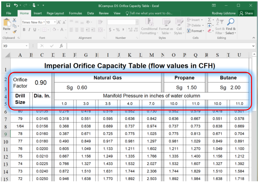
Figure 14 Image of BCcampus XLS Orifice Capacity Spreadsheet
In this example, we will use the information from Example 5 to size the orifices using the electronic table:
Furnace equipped with five burners having an input of 250,000 Btuh and operating at a manifold pressure of 7″ water column. The fuel gas being used is a propane-air mixture with a calorific value of 1,450 Btu/Ft.3 and a specific gravity of 1.2.
- Just as with our previous examples we will first need to calculate the volume flow rate per orifice of the alternate fuel.

- Using the Orifice Capacity Spreadsheet we will change one of the Sg values to 1.2 to match our alternate fuel gas. We will change the Natural Gas value as it already has a manifold pressure column that matches our required 7″ w.c. (Figure 15). The Propane or Butane sections could also be used but you would also need to change one of their manifold pressure values to 7″ w.c. Once the Sg value has been changed you will see that all of the flow values in the Natural Gas section have changed, and you can size the orifices directly from the modified table.
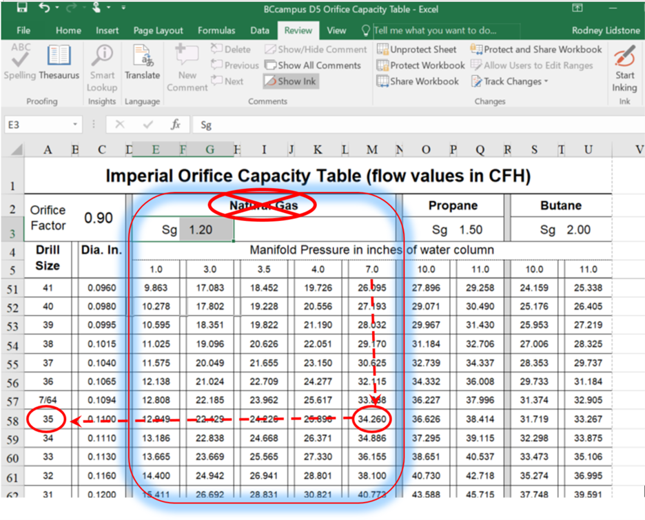
Figure 15 Image for example 6 of BCcampus XLS Orifice Capacity Spreadsheet
Notice the Natural Gas title has been crossed out in order to avoid any confusion, as the flow values in this highlighted area no longer reflect that of natural gas. It is advisable to not save any changes that you make to the factors in the spreadsheet so that the next time it is opened it will display the original settings. Alternately, you could save the modified version of the file with a different name.
Atmospheric pressure changes with a change in altitude, so the air pressure at higher elevations is usually lower than air pressure at sea level. This atmospheric pressure reduction is about 4% for every 1,000 feet of higher elevation. This reduction in atmospheric pressure affects the density of the air as well as the fuel gas. Boyles law tells us that the amount a gas expands will be inversely proportional to the absolute pressure applied to it. If the fuel gas expands by approximately 4% for every 1000 feet of increase elevation then the calorific value of the gas will be reduced by 4% from its sea level (standard conditions) value. To ensure that the gas appliance operates properly at higher elevations the rated input of the appliance must be reduced to accommodate these changes densities of the gas and air.
Derating Gas Appliances
Clause 4.22 of the CSA B149.1 Natural gas and propane installation code addresses adjusting appliances for high-altitude installations. Certified high-altitude appliances, with atmospheric burners, will typically have two input ratings, shown on the rating plate (Figure 16):
- Seal level rating which is considered to be the acceptable firing rate for the appliance when installed at elevations up to and including 2,000 feet (600m).
- High-altitude rating is to be used when the appliance is to be installed at elevations between 2,000 ft. (600m) and 4,500 ft. (1350m) and the orifices must be sized according to this rating.
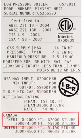
Figure 16 Rating plate with Canadian input ratings identified.
For example, the boiler rating plate shown in Figure 15 has a sea level (0 – 2,000 ft.) rating of 62,000 Btuh and a high altitude (2,000 – 4,500 ft.) rating of 55,800 Btuh. If this boiler is installed at an elevation between 0 – 2,000 ft., the orifices would be sized based on 62,000 Btuh. If the boiler is installed between 2,000 – 4,500 ft., the orifices would be sized on the 55,800 Btuh input.
Additionally, clause 4.22.2 stipulates that when an appliance is installed at an elevation above 4,500 ft (1,350 m), the certified high-altitude input rating shall be reduced at the rate of 4% for each additional
1,000 ft (300 m).
Therefore, if the appliance shown in Figure 15 was installed at 6500 ft the high-altitude rating would be reduced by 8% and the orifices would be sized based on an input of:
- 55.800 Btuh – 8% = 51,336 Btuh
For partial 1,000 ft. increments check with the equipment manufacture and the AHJ as the interpretation of the intent varies.
For example, if the previous appliance were installed at 7000 ft.
- Some jurisdictions may permit the use of interpolation for appliances installed between the 1,000 Ft. increments. In these cases the high-altitude input would be reduced by 10% for the 2500 ft, above 4500 ft.
- Others may deduct a full 4% for every 1000 ft or portion thereof. So the high altitude input would be reduce by 12% for the 2500 ft, above 4500 ft.
- Others may only deduct 4% for each full 1000 ft, increment. in which case high altitude input would be reduce by only 8% for the 2500 ft, above 4500 ft.
When resizing the orifices for the high elevation installation adjustments should be made to the orifice capacity tables to account for the fact that the gas will have a lower Sg therefore flow more easily through the orifice. The Sg of the gas decreases by approximately 2% for every 1000 ft. above sea level which will cause about a 1% increase the orifice flow rate.
Many modern appliances, that use non-atmospheric burners, will monitor combustion chamber and vent pressures and automatically adjust their gas input for variations caused by different atmospheric conditions. For example, the rating plate shown in Figure 17 has one input rating from seal level up to 4500 ft. for installations above 4500 ft. the installer will need to consult the manufacturer.
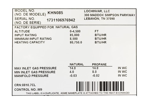
Figure 17 Non-atmospheric boiler rating plate
Whether an appliance burner has been re-orificed or not the Gas Safety Regulations requires that the installer test to ensure it is operating in accordance with the manufacturer’s specifications. Checking appliance operation can include tests of the; flue gas, temperature rise, manifold pressure, and verifying the burner orifice flow rate.
If the appliance is connected to natural gas, the most effective method of verifying the burner input is to use the gas utility companies gas meter (Figure 18) to check the fuel flow rate.
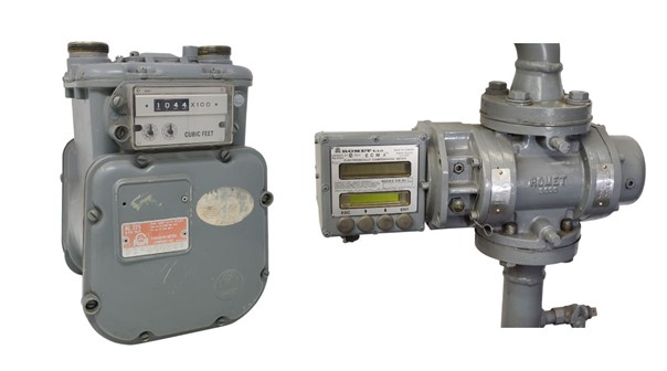
Figure 18 Gas meters -Diaphragm type left, Rotary type right
The different types of gas meters, their operation and different applications will be covered in later studies. For these lessons we will only focus on the part of the meter called the index or display that indicates the amount of gas flowing through it. The meter display can be used to calculate the actual appliance input.
Index Types
To know how to use the gas meter requires an understanding of what is information is being shown on the different types of meter index displays. There are three types of meter reading displays shown below:
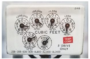
Figure 19 Dial type display
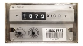
Figure 20 Direct read odometer type display
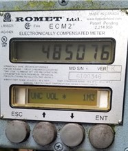
Figure 21 Direct read LED type display
On the dial type shown (Figure 19) there are four dials that are used by the utility to determine the overall consumption of gas through the meter. The bottom middle dial is not used for consumption purposes, it is used to either check for leaks in the downstream piping, or determine the appliance input. For the test dial shown in Figure 19 every complete revolution would indicate a flow of 5 cubic feet of gas though the meter.
For the odometer type index (Figure 20) the consumption is displayed with numbers, making it easier for the utility meter reader to record. This meter has two test dials of different volumes, that are of the dial type.
Modern rotary meters typically have an LED direct read display, with multiple readout screens for different functions. Instead of test dials the gasfitter will use the scroll push buttons to access the different screens. Figure 21 showed the consumption screen on display, whereas Figure 22 shows the flow rate screen, that can be used to check the appliance input.
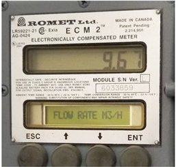
Figure 22 Rotary meter LED flow rate screen
Clocking the Meter
The process of using the utility meter to determine the input of a gas appliance is often called “clocking a meter”.
To make accurate calculations of the quantity of heat in the combustion chamber, the gas fitter must identify the calorific value of the gas in the piping system. If the calorific value is unknown, you should contact your local gas utility company.
The gas industry usually accepts the following calorific values for the three main fuel gases.
- natural gas – 1,000 Btu/cu ft or 10.35 kW/m3
- propane – 2,520 Btu/cu ft or 26 kW/m3
- butane – 3,260 Btu/cu ft or 33.7 kW/m3
Natural gas is usually the only value that is needed for clocking, as Propane or Butane systems are not typically supplied by a utility therefore a gas meter is not usually available.
Meter flow correction factors
The heat values used are typically for gas at standard conditions which are:
- pressure of 14.73 psia (Imperial) or 101.325 kPa (metric).
- temperature of 60°F (Imperial) or 15°C (metric).
As the gas flowing within the piping and meter is compressed the volume recorded by the meter may need to be corrected to determine the actual amount of standard conditions gas that is entering the appliance combustion chamber. For low pressure gas meter sets the gas compression is so minimal that no pressure correction calculations are needed, for high pressure meter sets (exceeding 0.5 psig) the index values will need to be corrected. On some meters there will actually be a tag indicating the proper correction factor to be used (Figure 23).
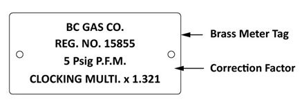
Figure 23 5 psig meter set correction factor tag
The pressure correction factor is a derivative of Boyles law which states:
The volume of any dry gas varies inversely with the absolute pressure when the temperature remains constant:

Remember, when dealing with gas laws, the units for pressure and temperature must be expressed in absolute terms. If using Boyles Law to calculate the actual volume of standard conditions gas (V2) flowing into the burner compared to every one unit of volume that the meter records (V1 =1) we can come up with the following pressure correction factor.
}= \dfrac{\small \text{Meter Gauge Pressure + Local Atmospheric Pressure}}{\text{Standard Pressure}}")
This formula can be used to verified the correction factor shown on the 5-psig meter in Figure 23:

Most gas meter indexes are temperature compensated, which means that the meter has a temperature adjustment device that continuously monitors the gas temperature and adjusts both the consumption and test dials to give a reading at standard or base temperature.
Clocking rotary meter (LED index)
When using a Rotary meter with an LED display, the flow rate displayed will need to be multiped by the appropriate heat value to give an input that matches the rating plate. It is important to ensure that only the one appropriate appliance is operating at the time that the index reading is recorded.
For example, the display shown in Figure 22 indicates a flow rate of 9.67 m3/h the input would be:
- 9.67 m3/h x 10.35 kW/m3= 100.08 kW
The input calculation may have to be converted between imperial or metric in order to compare with the rating plate value.
Conversion units:
- 1 Btuh = 0.000293 kW
- 1 kW = 3412 Btuh
The electronic flow rate display also known as the live flow rate, may or may not be pressure corrected depending on the parameter settings. You may have to contact the utility or meter manufacturer to verify which parameter are being displayed. If it is not a corrected value then it will have to be multiplied by a pressure correction factor.
Clocking test dial type meters
When using a gas meter with rotating circular test dials (Figure 19) dial type a stop watch is used to record the amount of time, in seconds, the dial takes to complete one full revolution. Watch the dial movement first to determine which volume test dial to use, when there is more than one choice (Figure 24), select the dial that is not moving to fast or to slow get an accurate volume reading. Choose a point in the rotation in which the dial is moving smoothly, as sometime you will notice a pause in the movement at the top and bottom of the rotation, therefore it would be best to not begin the clocking at those spots.
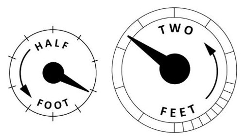
Figure 24 Rotating circular test dials
As was already mentioned low pressure gas meter sets the gas compression is so minimal that no pressure correction calculations are needed, for high pressure meter sets (exceeding 0.5 psig) the index values will need to be corrected.
Low Pressure clocking
The clocking formula for a gas meter were the pressure in the meter is up to 0.5 psig the following formula will determine the appliance firing rate.
} = \\ \small \dfrac{3600 \text{ Sec/Hr}}{\text{Sec/Revolution of Test Trial}} \times \text{Test Dial Volume/Revolution}\times \text{Calorific Value (Heat Quantity/Volume)}\end{array}")
A new furnace has been installed and fired on natural gas with a calorific value of 1,000 Btu/Ft3.The meter pressure is 7″ water column and the test dial being used is the half cubic foot. It takes 20 seconds for the test dial to make one complete revolution. What is the appliance input?

A new boiler has been installed and fired on natural gas with a calorific value of 10.35 kW/m3. The test dial being used is 0.05 m3 per revolution and the meter pressure is 3.5 kPa. What would the appliance input be if the test dial took 25 seconds to complete a revolution?

A new boiler has been installed and fired on natural gas with a calorific value of 1,000 Btu/Ft.3 The meter pressure is 7″ water column. The larger test dial is half cubic foot, but it is moving to quickly to get an accurate reading, In this case we will clock it for 4 revolutions divide the time by 4 revolutions to get a more accurate reading. It takes 32 seconds for the test dial to make four complete revolutions What is the appliance input?

High pressure clocking
These are the terms and definitions related to the high-pressure clocking formula:
- Meter Pressure – is the gauge pressure of the gas flowing through the meter expressed in either Psig or kPa.
- Local Atmospheric Pressure – is the atmospheric pressure for the locality of the meter installation expressed in Psia or kPa.
- Standard Pressure – is the term for the absolute pressure at the heat value of the gas is base typically these are standard conditions values of 14.73 Psia or 101.325 kPa unless otherwise stated. For installations at higher elevations you should verify the heat value and base pressure for that area. The heat value may already be reduced for that region, in which case it is important to use the pressure standard that is relevant to that reduced regional heat value.
For high pressure clocking the same low-pressure clocking formula is used, with the addition of the pressure correction factor. Any high-pressure meter that is not temperature compensated would also require a temperature correction factor
A gas appliance is clocked through a temperature compensated gas meter at a pressure of 5 Psig. One revolution of the two cubic foot test dial took 40 seconds. The local atmospheric pressure in the area is 14.60 Psi. Calculate the input in Btuh using standard conditions natural gas at 1,000 Btu/Ft3.

A gas appliance is clocked through a temperature compensated gas meter at a pressure of 35 kPa. One revolution of the test dial takes 30 seconds on a 0.05 cubic meter test dial. The local atmospheric pressure of the area is 96.25 kPa. Calculate the input using standard conditions natural gas with a calorific value of 10.35 kW/m3.

Verifying an Installed Orifice Size
When selecting an orifice size, you would typically work from the appliance rating plate input. There may also be instances where you will want to check the actual orifice size that has been installed in the appliance without removing and measuring it. In these cases, the appliance clocked input can be used to determine the input or flow rate per orifice to verify the orifice size.
You have been called to check out a natural furnace that doesn’t seem to be giving the necessary heat output. After verifying the correct manifold pressure of 3″ WC as per the rating plate, you decide to clock the appliance input. The meter set has a temperature compensated gas meter at a pressure of 2 psig. One revolution of the .05 cubic foot test dial took 30 seconds. The local atmospheric pressure in the area is 14.73 Psi. Calculate the input in Btuh using standard conditions natural gas at 1,000 Btu/Ft3. and confirm the orifice size for the three burners.

This is substantially lower than the rating plate input of 200,000 Btuh, so before removing and components you decide to check the orifice size from the clocked input.
Determining the orifice sizes:
- Select an orifice capacity table with matching; Gas. CV, Sg, manifold pressure and orifice K-factor. For this example, we will say that our orifices are 0.90 K-factor to match the Appendix 2 table
- From the table confirm the orifice flow value that is used. In this case the table expresses the flow values as flow rate per orifice in CFH (ft3/hr)
- Calculate the flow rate per orifice.
- Follow down appropriate (Natural gas) manifold pressure column of 3.0″WC (Figure 11) until a flow rate (equal to or less than) the clocked 22.75 CFH is found.
- The closest value to 22.75 CFH is 22.917, if you were selecting an orifice this would the wrong choice as it would slightly overfired but, in this case, you are just trying to find out what orifice is in the burners and this one is the closest choice. Looking directly to the far left of that row the orifice size would be No. 42.
- This would be the orifice installed in the appliance based on the actual clocked input, it is not the correct orifice as the rating plate indicates that a No. 21 orifices are required when operating this appliance on natural gas.
- Further investigation concludes that this appliance was actually shipped with the propane orifices installed and the input was not checked by the original installer.
 Now complete E-5 LT3 Self-Test and check your answers.
- There are two methods of changing the input to the burner, one is by adjusting the manifold pressure what is the other?
- Change the Vent size
- Adjust the primary air shutters
- Changing the size of the orifices.
- Increasing the gas meter pressure
- The three common types of main burner orifices are:
- Spud, Pilot, and Cap
- Fixed, Adjustable, Cap
- Drilled, Universal, Appliance
- Adjustable, Flared, Universal
- Which type of orifice can commonly be found on dual fuel (propane and natural gas) appliances?
- Spud type
- Insert type
- Calibrated
- Cap or Universal
- How is a residential range with universal orifices converted from propane to natural gas?
- Adjusting the primary air shutters
- Decreasing the manifold pressure
- Turn the orifice cap clockwise and change the regulator setting
- Turn the orifice cap counter-clockwise and change the regulator setting
- It is the diameter that is used to calculate the flow rate through an orifice not the area.
- True
- False
- Select the smallest drill size from the four choices.
- #40
- #41
- 2.45 mm
- 3/32″
- Which of the following factors does not affect the sizing of the burner orifice?
- Type of gas
- Position of the burner in relation to the pilot
- Appliance input
- Manifold pressure
- Use the orifice flow formula to determine the area of the orifices for a 100 MBH appliance with 4 burners operating on natural gas (Sg 0.6, 1000 Btu/ft3) at a manifold pressure of 2 inches of water column using orifice with a 0.9 K factor.
- Step 1
} \\ = \dfrac{\text{Input of appliance (Btuh)}}{\text{Number of orifices}} \div \text{calorific value of the gas (Btu/}{ft}^{3}) \end{array}")
- Step 2

- 0.0065 in2
- 0.0091 in2
- 0.0367 in2
- 0.0980 in2
Use the Appendix 2 orifice capacity table to answer the following self test questions.
- Determine the orifice sizes for a forced warm air furnace is to be fired on natural gas having a calorific value of 1,000 Btu/Ft3. and an Sg of 0.60. The appliance rating plate lists an input of 120,000 Btuh and a manifold pressure of 4.0 inches water column. The furnace has three burners.
- #15
- #32
- #33
- #43
- Determine the orifice size for a forced storage type water heater to be fired on propane gas having a calorific value of 2,500 Btu/Ft3. and an Sg of 1.50. The appliance rating plate lists an input of 60,000 Btuh and a manifold pressure of 11.0 inches water column. The furnace has one upshot burner.
- #41
- #42
- #43
- #44
- When an appliance is installed at an elevation above 4,500 ft (1,350 m), the certified high-altitude input rating shall be reduced at the rate of 2% for each additional 1,000 ft (300 m).
- True
- False
- When using a rotary meter to clock a boiler the LED flow rate screen meter indicates 3.54 m3/h of natural gas. What is the appliance input?
- 36.64 kW
- 3,540 Btuh
- 3,540 kW
- 12,078 kW
- A new gas appliance has been installed and fired on natural gas with a calorific value of 1,000 Btu/Ft3. The meter pressure is 7″ water column and the test dial being used is the half cubic foot. It takes 30 seconds for the test dial to make one complete revolution. What is the appliance input?
- 30,000 Btuh
- 45,000 Btuh
- 60,000 Btuh
- 120,000 Btuh
- A gas appliance is clocked through a temperature compensated high pressure gas meter at a pressure of 35 kPa. One revolution of the test dial takes 20 seconds on a 0.025 cubic meter test dial. The local atmospheric pressure of the area is 97.25 kPa. Calculate the input using standard conditions natural gas with a calorific value of 10.35 kW/m3.
- 46.58 kW
- 60.79 kw
- 93.15 kw
- 5873.43 Kw
- The propane gas orifice sizes are smaller then the required natural gas orifices for the same appliance.
- True
- False
Check your answers using the Self-Test Answer Keys in Appendix 1.
Media Attributions
- Figure 1 “Orifice Spud” by Camosun College is licensed under a CC BY 4.0 licence.
- Figure 2 “Gas range Cap orifice” by Camosun College is licensed under a CC BY 4.0 licence.
- Figure 3 “Cap orifice setup for propane” by Camosun College is licensed under a CC BY 4.0 licence.
- Figure 4 “Cap orifice setup for natural gas” by Camosun College is licensed under a CC BY 4.0 licence.
- Figure 5 “Adjustable orifice” by Camosun College is licensed under a CC BY 4.0 licence.
- Figure 6 “Spud type pilot orifice” by Camosun College is licensed under a CC BY 4.0 licence.
- Figure 7 “Insert type pilot orifice” by Camosun College is licensed under a CC BY 4.0 licence.
- Figure 8 “Burner Showing Gas Flow through an Orifice” by Camosun College is licensed under a CC BY 4.0 licence.
- Figure 9 “Twist drill index” by Camosun College is licensed under a CC BY 4.0 licence.
- Figure 10 “Finger orifice drill set” by Camosun College is licensed under a CC BY 4.0 licence.
- Figure 11 Example 1 excerpt from Natural gas and propane installation code by BCcampus is licensed under a CC BY 4.0 licence.
- Figure 12 Example 2 excerpt from Natural gas and propane installation code by BCcampus is licensed under a CC BY 4.0 licence.
- Figure 13 excerpt from Appendix 2 Table is licensed under a CC BY 4.0 licence.
- Figure 14 “Image of BCcampus XLS Orifice Capacity Spreadsheet” is licensed under a CC BY 4.0 licence.
- Figure 15 “Image for example 6 of BCcampus XLS Orifice Capacity Spreadsheet” is licensed under a CC BY 4.0 licence.
- Figure 16 “Rating plate with Canadian input ratings identified” by Camosun College is licensed under a CC BY 4.0 licence.
- Figure 17 “Non-atmospheric boiler rating plate” by Camosun College is licensed under a CC BY 4.0 licence.
- Figure 18 “Gas meters (diaphragm type and rotary)” by Camosun College is licensed under a CC BY 4.0 licence.
- Figure 19 “Dial type display” by Camosun College is licensed under a CC BY 4.0 licence.
- Figure 20 “Direct read odometer type display” by Camosun College is licensed under a CC BY 4.0 licence.
- Figure 21 “Direct read LED type display” by Camosun College is licensed under a CC BY 4.0 licence.
- Figure 22 “Rotary meter LED flow rate screen” by Camosun College is licensed under a CC BY 4.0 licence.
- Figure 23 “5 psig meter set correction factor tag” by Camosun College is licensed under a CC BY 4.0 licence.
- Figure 24 “Rotating circular test dials” by Camosun College is licensed under a CC BY 4.0 licence.


.jpg)