<?xml version="1.0" encoding="UTF-8"?>
<!DOCTYPE html PUBLIC "-//W3C//DTD XHTML 1.1//EN" "http://www.w3.org/TR/xhtml11/DTD/xhtml11.dtd">
<html xmlns="http://www.w3.org/1999/xhtml" xml:lang="en">
<head>
<meta content="text/html; charset=UTF-8" http-equiv="content-type" />
<meta http-equiv="Content-Language" content="en" />
<meta name="generator" content="Pressbooks 6.22.1" />
<meta name="pb-authors" content="SkilledTradesBC" />
<meta name="pb-title" content="Block E: Transition to Journeyperson" />
<meta name="pb-language" content="en-ca" />
<meta name="pb-cover-image" content="https://opentextbc.ca/plumbing4e/wp-content/uploads/sites/465/2024/11/Block-E-Transition-To-Journeyperson-1.jpg" />
<meta name="pb-subtitle" content="Plumbing Apprenticeship Program Level 4" />
<meta name="pb-primary-subject" content="TNTP" />
<meta name="pb-copyright-holder" content="SkilledTradesBC" />
<meta name="pb-book-license" content="cc-by-nc-sa" />
<meta name="pb-custom-copyright" content="© 2025 SkilledTradesBCThe CC licence permits you to retain, reuse, copy, redistribute, and revise this book—in whole or in part—for free providing it is for non-commercial purposes, and adapted and reshared content retains the same licence, and the author is attributed as follows:Block E: Transition to Journeyperson by SkilledTradesBC is licensed under a CC BY-NC-SA 4.0 licence.If you redistribute all or part of this book, it is recommended the following statement be added to the copyright page so readers can access the original book at no cost:Download for free from the B.C. Open Collection.Sample APA-style citation (7th Edition):SkilledTradesBC. (2025). Block E: Transition to journeyperson. BCcampus. https://opentextbc.ca/plumbing4e/Cover image attribution:“person drafting on blueprint” by Daniel McCullough (d_mccullough) is licensed under an Unsplash licence.Ebook ISBN: 978-1-77420-273-9Print ISBN: 978-1-77420-272-2Visit BCcampus Open Education to learn about open education in British Columbia." />
<meta name="pb-publisher" content="BCcampus" />
<meta name="pb-publisher-city" content="Victoria, B.C." />
<meta name="pb-about-50" content="The content of this block is intended to prepare the plumber apprentice for the transition to journeyperson. This block discusses practices and strategies for project management, how to coordinate work with others trades, and mentoring techniques and communication skills that can support developing positive working relationships. Each competency includes a list of leaning objectives and each learning task includes a self-test to enable students to check their understanding of the content." />
<meta name="pb-publication-date" content="1746489600" />
<meta name="pb-ebook-isbn" content="978-1-77420-273-9" />
<meta name="pb-print-isbn" content="978-1-77420-272-2" />
<title>Block E: Transition to Journeyperson</title>
</head>
<body lang='en' >
<div id="half-title-page"><h1 class="title">Block E: Transition to Journeyperson</h1></div>
<div id="title-page">
			<h1 class="title">Block E: Transition to Journeyperson</h1>
		<h2 class="subtitle">Plumbing Apprenticeship Program Level 4</h2>
					<p class="author">SkilledTradesBC</p>
								<p class="publisher">BCcampus</p>
		<p class="publisher-city">Victoria, B.C.</p>
	</div>
<div id="copyright-page">
	<div class="ugc">
					
<div class="license-attribution"><p><img src="https://opentextbc.ca/plumbing4e/wp-content/themes/pressbooks-book/packages/buckram/assets/images/cc-by-nc-sa.svg" alt="Icon for the Creative Commons Attribution-NonCommercial-ShareAlike 4.0 International License" /></p><p>Block E: Transition to Journeyperson Copyright © 2025 by <span>SkilledTradesBC</span> is licensed under a <a rel="license" href="https://creativecommons.org/licenses/by-nc-sa/4.0/">Creative Commons Attribution-NonCommercial-ShareAlike 4.0 International License</a>, except where otherwise noted.</p></div>

							<p>© 2025 SkilledTradesBC</p><p>The CC licence permits you to retain, reuse, copy, redistribute, and revise this book—in whole or in part—for free providing it is for non-commercial purposes, and adapted and reshared content retains the same licence, and the author is attributed as follows:</p><div class="textbox"><a href="https://opentextbc.ca/plumbing4e/"><em>Block E: Transition to Journeyperson</em></a> by SkilledTradesBC is licensed under a <a href="https://creativecommons.org/licenses/by-nc-sa/4.0/deed.en">CC BY-NC-SA 4.0 licence</a>.</div><p>If you redistribute all or part of this book, it is recommended the following statement be added to the copyright page so readers can access the original book at no cost:</p><div class="textbox">Download for free from the <a href="https://collection.bccampus.ca/">B.C. Open Collection</a>.</div><p><strong>Sample APA-style citation (7th Edition):</strong></p><div class="textbox">SkilledTradesBC. (2025). <i>Block E: Transition to journeyperson</i>. BCcampus. https://opentextbc.ca/plumbing4e/</div><p><strong>Cover image attribution:</strong></p><div class="textbox"><a title="https://unsplash.com/photos/person-drafting-on-blueprint--FPFq_trr2Y" href="https://unsplash.com/photos/person-drafting-on-blueprint--FPFq_trr2Y">&#8220;person drafting on blueprint”</a> by <a title="https://unsplash.com/@d_mccullough" href="https://unsplash.com/@d_mccullough">Daniel McCullough (d_mccullough)</a> is licensed under an <a title="https://unsplash.com/license" href="https://unsplash.com/license">Unsplash licence</a>.</div><p><strong>Ebook ISBN: </strong>978-1-77420-273-9</p><p><strong>Print ISBN: </strong>978-1-77420-272-2</p><p>Visit <a href="http://open.bccampus.ca/">BCcampus Open Education</a> to learn about open education in British Columbia.</p>
							</div>
</div>
<div id="toc">
	<h1>Contents</h1>
	<ul>
					<li class="front-matter introduction">
	<a href="#front-matter-accessibility-statement">
		<span class="toc-chapter-title">Accessibility Statement</span>
							</a>
	</li>

					<li class="front-matter post-introduction miscellaneous">
	<a href="#front-matter-for-students-how-to-access-and-use-this-textbook">
		<span class="toc-chapter-title">For Students: How to Access and Use this Textbook</span>
							</a>
	</li>

					<li class="front-matter miscellaneous">
	<a href="#front-matter-about-bccampus-open-education">
		<span class="toc-chapter-title">About BCcampus Open Education</span>
							</a>
	</li>

					<li class="part">
	<a href="#part-describe-project-management">
					Competency E1: Describe Project Management
			</a>
</li>

					<li class="chapter standard">
	<a href="#chapter-describe-contractual-documents">
		<span class="toc-chapter-title">Learning Task 1</span>
					<span class="chapter-subtitle">Describe Contractual Documents</span>
							</a>
	</li>

					<li class="chapter standard">
	<a href="#chapter-describe-records-management">
		<span class="toc-chapter-title">Learning Task 2</span>
					<span class="chapter-subtitle">Describe Records Management</span>
							</a>
	</li>

					<li class="part">
	<a href="#part-coordinate-cross-trade-activities">
					Competency E2: Coordinate Cross Trade Activities
			</a>
</li>

					<li class="chapter standard">
	<a href="#chapter-identify-potential-installation-conflicts-between-trades">
		<span class="toc-chapter-title">Learning Task 1</span>
					<span class="chapter-subtitle">Identify Potential Installation Conflicts Between Trades</span>
							</a>
	</li>

					<li class="chapter standard">
	<a href="#chapter-describe-areas-technical-expertise-trade-overlap">
		<span class="toc-chapter-title">Learning Task 2</span>
					<span class="chapter-subtitle">Describe Areas of Technical Expertise That Have Trade Overlap</span>
							</a>
	</li>

					<li class="chapter standard">
	<a href="#chapter-describe-electric-motors">
		<span class="toc-chapter-title">Learning Task 3</span>
					<span class="chapter-subtitle">Describe Electric Motors</span>
							</a>
	</li>

					<li class="chapter standard">
	<a href="#chapter-interpret-sections-canadian-electrical-code">
		<span class="toc-chapter-title">Learning Task 4</span>
					<span class="chapter-subtitle">Interpret Sections of the Canadian Electrical Code</span>
							</a>
	</li>

					<li class="chapter standard">
	<a href="#chapter-section-2">
		<span class="toc-chapter-title">Section 2</span>
					<span class="chapter-subtitle">General Rules</span>
							</a>
	</li>

					<li class="chapter standard">
	<a href="#chapter-section-4">
		<span class="toc-chapter-title">Section 4</span>
					<span class="chapter-subtitle">Conductors</span>
							</a>
	</li>

					<li class="chapter standard">
	<a href="#chapter-section-8">
		<span class="toc-chapter-title">Section 8</span>
					<span class="chapter-subtitle">Circuit Loading and Demand Factors</span>
							</a>
	</li>

					<li class="chapter standard">
	<a href="#chapter-section-10">
		<span class="toc-chapter-title">Section 10</span>
					<span class="chapter-subtitle">Grounding and Bonding</span>
							</a>
	</li>

					<li class="chapter standard">
	<a href="#chapter-section-12">
		<span class="toc-chapter-title">Section 12</span>
					<span class="chapter-subtitle">Wiring Methods</span>
							</a>
	</li>

					<li class="chapter standard">
	<a href="#chapter-bc-electrical-safety-regulation">
		<span class="toc-chapter-title">BC Electrical Safety Regulation</span>
							</a>
	</li>

					<li class="part">
	<a href="#part-use-mentoring-techniques">
					Competency E3: Use Mentoring Techniques
			</a>
</li>

					<li class="chapter standard">
	<a href="#chapter-describe-effective-mentoring-techniques">
		<span class="toc-chapter-title">Learning Task 1</span>
					<span class="chapter-subtitle">Describe Effective Mentoring Techniques</span>
							</a>
	</li>

					<li class="chapter standard">
	<a href="#chapter-describe-learning-strategies">
		<span class="toc-chapter-title">Learning Task 2</span>
					<span class="chapter-subtitle">Describe Learning Strategies</span>
							</a>
	</li>

					<li class="back-matter appendix">
	<a href="#back-matter-versioning-history">
		<span class="toc-chapter-title">Versioning History</span>
							</a>
	</li>

			</ul>
</div>
<div class="front-matter introduction " id="front-matter-accessibility-statement" title="Accessibility Statement">
	<div class="front-matter-title-wrap">
		<p class="front-matter-number">1</p>
		<h1 class="front-matter-title">Accessibility Statement</h1>
								</div>
	<div class="ugc front-matter-ugc">
				 <p>BCcampus Open Education believes that education must be available to everyone. This means supporting the creation of free, open, and accessible educational resources. We are actively committed to increasing the accessibility and usability of the textbooks we produce.</p> <h1>Accessibility of This Resource</h1> <p>BCcampus was requested to make this resource available to students starting in January 2025 and, as a result, we are making this book public before all of our production work is finished, namely image descriptions and attributions. Due to this, this book does not meet our accessibility standards at the time of publication. We will be continuing to work on these steps after the book has been made public and these issues will be resolved at a later date.</p> <p>In the mean time, we have done our best to be transparent about the existing accessibility barriers and features below:</p> <table class="grid" style="width: 100%;"><caption>Accessibility Checklist</caption> <tbody><tr><th scope="col">Element</th> <th scope="col">Requirements</th> <th scope="col">Pass?</th> </tr> <tr><th scope="row">Headings</th> <td>Content is organized under headings and subheadings that are used sequentially.</td> <td>Yes</td> </tr> <tr><th scope="row">Images</th> <td>Images that convey information include alternative text descriptions. These descriptions are provided in the alt text field, in the surrounding text, or linked to as a long description.</td> <td>Yes</td> </tr> <tr><th scope="row">Images</th> <td>Images and text do not rely on colour to convey information.</td> <td>Yes</td> </tr> <tr><th scope="row">Images</th> <td>Images that are purely decorative or are already described in the surrounding text contain empty alternative text descriptions. (Descriptive text is unnecessary if the image doesn’t convey contextual content information.)</td> <td>Yes</td> </tr> <tr><th scope="row">Tables</th> <td>Tables include row and/or column headers that have the correct scope assigned.</td> <td>Yes</td> </tr> <tr><th scope="row">Tables</th> <td>Tables include a title or caption.</td> <td>Yes</td> </tr> <tr><th scope="row">Tables</th> <td>Tables do not have merged or split cells.</td> <td>Yes</td> </tr> <tr><th scope="row">Tables</th> <td>Tables have adequate cell padding.</td> <td>Yes</td> </tr> <tr><th scope="row">Links</th> <td>The link text describes the destination of the link.</td> <td>Yes</td> </tr> <tr><th scope="row">Links</th> <td>Links do not open new windows or tabs. If they do, a textual reference is included in the link text.</td> <td>Yes</td> </tr> <tr><th><strong>Links</strong></th> <td>Links to files include the file type in the link text.</td> <td>Yes</td> </tr> <tr><th><strong>Audio</strong></th> <td>All audio content includes a transcript that includes all speech content and relevant descriptions of non-speach audio and speaker names/headings where necessary.</td> <td>N/A</td> </tr> <tr><th scope="row">Video</th> <td>All videos include high-quality (i.e., not machine generated) captions of all speech content and relevant non-speech content.</td> <td>N/A</td> </tr> <tr><th scope="row">Video</th> <td>All videos with contextual visuals (graphs, charts, etc.) are described audibly in the video.</td> <td>Yes</td> </tr> <tr><th>H5P</th> <td>All H5P activities have been tested for accessibility by the H5P team and have passed their testing.</td> <td>Yes</td> </tr> <tr><th>H5P</th> <td>All H5P activities that include images, videos, and/or audio content meet the accessibility requirements for those media types.</td> <td>N/A</td> </tr> <tr><th scope="row">Formulas</th> <td>Formulas have been created using LaTeX and are rendered with MathJax.</td> <td>N/A</td> </tr> <tr><th scope="row">Formulas</th> <td>If LaTeX is not an option, formulas are images with alternative text descriptions.</td> <td>N/A</td> </tr> <tr><th scope="row">Font</th> <td>Font size is 12 point or higher for body text.</td> <td>Yes</td> </tr> <tr><th scope="row">Font</th> <td>Font size is 9 point for footnotes or endnotes.</td> <td>Yes</td> </tr> <tr><th scope="row">Font</th> <td>Font size can be zoomed to 200% in the webbook or eBook formats.</td> <td>Yes</td> </tr> </tbody> </table> <h1>Let Us Know if You are Having Problems Accessing This Book</h1> <p>We are always looking for ways to make our resources more accessible. If you have problems accessing this resource, please contact us to let us know so we can fix the issue.</p> <p>Please include the following information:</p> <ul><li>The name of the resource</li> <li>The location of the problem by providing a web address or page description.</li> <li>A description of the problem</li> <li>The computer, software, browser, and any assistive technology you are using that can help us diagnose and solve your issue (e.g., Windows 10, Google Chrome (Version 65.0.3325.181), NVDA screen reader)</li> </ul> <p>You can contact us one of the following ways:</p> <ul><li>Web form: <a href="https://collection.bccampus.ca/contact/" data-url="https://collection.bccampus.ca/contact/">BCcampus Open Ed Help</a></li> <li>Web form: <a href="https://collection.bccampus.ca/report-error" data-url="https://collection.bccampus.ca/report-error">Report an Error</a></li> </ul> <p>This statement was last updated on May 5th, 2025.</p> <p>The Accessibility Checklist table was adapted from one originally created by the <a href="https://press.rebus.community/the-rebus-guide-to-publishing-open-textbooks/back-matter/accessibility-assessment/" data-url="https://press.rebus.community/the-rebus-guide-to-publishing-open-textbooks/back-matter/accessibility-assessment/">Rebus Community</a> and shared under a <a href="https://creativecommons.org/licenses/by/4.0/" data-url="https://creativecommons.org/licenses/by/4.0/">CC BY 4.0 License</a>.</p> 
	</div>


	</div>
<div class="front-matter miscellaneous post-introduction " id="front-matter-for-students-how-to-access-and-use-this-textbook" title="For Students: How to Access and Use this Textbook">
	<div class="front-matter-title-wrap">
		<p class="front-matter-number">2</p>
		<h1 class="front-matter-title">For Students: How to Access and Use this Textbook</h1>
								</div>
	<div class="ugc front-matter-ugc">
				 <p>This textbook is available in the following formats:</p> <ul><li><strong>Online webbook</strong>. You can read this textbook online on a computer or mobile device in one of the following browsers: Chrome, Firefox, Edge, and Safari.</li> <li><strong>PDF</strong>. You can download this book as a PDF to read on a computer (Digital PDF) or print it out (Print PDF).</li> <li><strong>Mobile</strong>. If you want to read this textbook on your phone or tablet, you can use the EPUB (eReader) file.</li> <li><strong>HTML</strong>. An HTML file can be opened in a browser. It has very little style so it doesn’t look very nice, but some people might find it useful.</li> </ul> <p>For more information about the accessibility of this textbook, see the Accessibility Statement.</p> <p>You can access the online webbook and download any of the formats for free here:&nbsp;<a href="https://opentextbc.ca/plumbing4e/" data-url="https://opentextbc.ca/plumbing4e/"><em>Block E: Transition to Journeyperson</em></a>.&nbsp;To download the book in a different format, look for the “Download this book” drop-down menu and select the file type you want.</p> <table><caption>How can I use the different formats?</caption> <tbody><tr><th scope="col">Format</th> <th scope="col">Internet required?</th> <th scope="col">Device</th> <th scope="col">Required apps</th> <th scope="col">Accessibility Features</th> <th scope="col">Screen reader compatible</th> </tr> <tr><td>Online webbook</td> <td>Yes</td> <td>Computer, tablet, phone</td> <td>An Internet browser (Chrome, Firefox, Edge, or Safari)</td> <td>WCAG 2.0 AA compliant, option to enlarge text, and compatible with browser text-to-speech tools</td> <td>Yes</td> </tr> <tr><td>PDF</td> <td>No</td> <td>Computer, print copy</td> <td>Adobe Reader (for reading on a computer) or a printer</td> <td>Ability to highlight and annotate the text. If reading on the computer, you can zoom in.</td> <td>Unsure</td> </tr> <tr><td>EPUB</td> <td>No</td> <td>Computer, tablet, phone</td> <td>An eReader app</td> <td>Option to enlarge text, change font style, size, and colour.</td> <td>Unsure</td> </tr> <tr><td>HTML</td> <td>No</td> <td>Computer, tablet, phone</td> <td>An Internet browser (Chrome, Firefox, Edge, or Safari)</td> <td>WCAG 2.0 AA compliant and compatible with browser text-to-speech tools.</td> <td>Yes</td> </tr> </tbody> </table> <h1>Tips for Using This Textbook</h1> <ul><li><strong>Search the textbook</strong>. <ul><li>If using the online webbook, you can use the search bar in the top right corner to search the entire book for a key word or phrase. To search a specific chapter, open that chapter and use your browser’s search feature by hitting <strong>[Cntr] + [f]</strong> on your keyboard if using a Windows computer or <strong>[Command] + [f] </strong>if using a Mac computer.</li> <li>The <strong>[Cntr] + [f]</strong> and <strong>[Command] + [f]</strong> keys will also allow you to search a PDF, HTML, and EPUB files if you are reading them on a computer.</li> <li>If using an eBook app to read this textbook, the app should have a built-in search tool.</li> </ul> </li> <li><strong>Navigate the textbook</strong>. <ul><li>This textbook has a table of contents to help you navigate through the book easier. If using the online webbook, you can find the full table of contents on the book’s homepage or by selecting “Contents” from the top menu when you are in a chapter.</li> </ul> </li> <li><strong>Annotate the textbook</strong>. <ul><li>If you like to highlight or write on your textbooks, you can do that by getting a print copy, using the Digital PDF in Adobe Reader, or using the highlighting tools in eReader apps.</li> </ul> </li> </ul> <h1>Webbook vs. All Other Formats</h1> <p>The webbook includes H5P Interactive Activities. If you are not using the webbook to access this textbook, this content will not be included. Instead, your copy of the text will provided a link to where you can access that content online.</p> <p>Even if you decide to use a PDF or a print copy to access the textbook, you can access the webbook and download any other formats at any time.</p> 
	</div>


	</div>
<div class="front-matter miscellaneous post-introduction " id="front-matter-about-bccampus-open-education" title="About BCcampus Open Education">
	<div class="front-matter-title-wrap">
		<p class="front-matter-number">3</p>
		<h1 class="front-matter-title">About BCcampus Open Education</h1>
								</div>
	<div class="ugc front-matter-ugc">
				 <p><a href="https://opentextbc.ca/plumbing4e/" data-url="https://opentextbc.ca/plumbing4e/"><em>Block E: Trnsition to Journeyman</em></a> by SkilledTradesBC was funded by BCcampus Open Education.</p> <p><a href="https://open.bccampus.ca/" data-url="https://open.bccampus.ca/">BCcampus Open Education</a> began in 2012 as the B.C. Open Textbook Project with the goal of making post-secondary education in British Columbia more accessible by reducing students’ costs through the use of open textbooks and other OER. <a href="https://bccampus.ca/" data-url="https://bccampus.ca/">BCcampus</a> supports the post-secondary institutions of British Columbia as they adapt and evolve their teaching and learning practices to enable powerful learning opportunities for the students of B.C. BCcampus Open Education is funded by the <a href="https://www2.gov.bc.ca/gov/content/governments/organizational-structure/ministries-organizations/ministries/post-secondary-education-and-future-skills" rel="noopener" data-url="https://www2.gov.bc.ca/gov/content/governments/organizational-structure/ministries-organizations/ministries/post-secondary-education-and-future-skills">Ministry of Post-Secondary Education and Future Skills</a> and the <a href="http://www.hewlett.org/" rel="noopener" data-url="http://www.hewlett.org/">Hewlett Foundation</a>.</p> <p>Open educational resources (OER) are teaching, learning, and research resources that, through permissions granted by the copyright holder, allow others to use, distribute, keep, or make changes to them. Our open textbooks are openly licensed using a <a href="https://creativecommons.org/licenses/" data-url="https://creativecommons.org/licenses/">Creative Commons licence</a> and are offered in various eBook formats free of charge, or as printed books that are available at cost.</p> <p>For more information about open education in British Columbia, please visit the <a href="https://open.bccampus.ca/" data-url="https://open.bccampus.ca/">BCcampus Open Education</a> website. If you are an instructor who is using this book for a course, please fill out our <a href="https://open.bccampus.ca/use-open-textbooks/tell-us-youre-using-an-open-textbook/" data-url="https://open.bccampus.ca/use-open-textbooks/tell-us-youre-using-an-open-textbook/">Adoption of an Open Textbook</a> form.</p> <div class="textbox">This book was produced using the following styles: <a href="https://opentextbc.ca/plumbing4e/wp-content/uploads/sites/465/2024/11/Plumbing-Level-4-Series-Style-Sheet.docx" data-url="https://opentextbc.ca/plumbing4e/wp-content/uploads/sites/465/2024/11/Plumbing-Level-4-Series-Style-Sheet.docx">Plumbing Level 4 Series Style Sheet [Word file]</a></div> 
	</div>


	</div>
<div class="part-wrapper" id="part-describe-project-management-wrapper">
    <div class="part  " id="part-describe-project-management">
	<div class="part-title-wrap">
		<p class="part-number">I</p>
		<h1 class="part-title">Competency E1: Describe Project Management</h1>
	</div>
	<div class="ugc part-ugc">
		<p>Regardless of the size and type of construction project being considered, there must be a framework in place that defines the roles, responsibilities, and “work” to be undertaken by a contractor, their employees, and all those connected to the project. The creation of contractual documents provides the basis for the undertakings of owners, contractors, subcontractors, and workers in their quest to deliver the product in an orderly and trackable fashion that is also legally binding. This section will concentrate of the description of the contractual documents involved in residential, commercial, and institutional construction, with a focus on requirements specific to British Columbia.</p> <div class="textbox textbox--learning-objectives"><div class="textbox__header"><p class="textbox__title">Learning Objectives</p> </div> <div class="textbox__content"><p>After completing the learning tasks in this competency, you will be able to:</p> <ul><li>describe the purpose and types of contractual documents in construction</li> <li>identify responsibilities and obligations of contractors and workers</li> <li>describe the various documents involved in record management</li> </ul> </div> </div> <h1>Some Helpful Acronyms</h1> <p>In British Columbia, there are several associations that can be accessed for guidance through the construction process. Some of them and their acronyms are:</p> <ul><li>BCCA – British Columbia Construction Association</li> <li>CCA – Canadian Construction Association</li> <li>AIBC – Architectural Institute of British Columbia</li> <li>ACEC – Association of Consulting Engineering Companies of British Columbia</li> <li>CCDC – Canadian Construction Documents Committee</li> <li>BCDC – British Columbia Documents Committee</li> <li>SAC – Surety Association of Canada</li> <li>CSI – Construction Specifications Institute</li> <li>CSC – Construction Specifications Canada</li> </ul> <p>Although the focus of the associations listed above leans toward commercial and industrial projects, the information within them can be applied to residential installations as well. On a residential construction level, the two associations that can provide additional information and guidance are:</p> <ul><li>CHBA – Canadian Home Builders’ Association, and</li> <li>CHBA BC – Canadian Home Builders’ Association of British Columbia</li> </ul>
	</div>
			
				
	</div>
<div class="chapter standard " id="chapter-describe-contractual-documents" title="Learning Task 1">
	<div class="chapter-title-wrap">
		<p class="chapter-number">1</p>
		<h1 class="chapter-title">Learning Task 1</h1>
					<p class="chapter-subtitle">Describe Contractual Documents</p>
			</div>
	<div class="ugc chapter-ugc">
				 <h1>Contracts and Agreements</h1> <p>The purpose of contractual documents, called contracts or agreements, is to provide clear direction on the roles and responsibilities of owners, managers, and contractors. Owners are rarely directly involved in the day-to-day operations on a jobsite, unless the project is relatively small and they have experience in managing trades contractors. On larger or more extensive construction sites, project managers (also known as general contractors) are the link between owners and trades workers. They take on the oversight of a project by managing the trades contractors (known as subcontractors). Subcontractors are responsible for work such as plumbing, electrical, HVAC and carpentry, and are generally overseen by the project manager who reports directly back to the owner. Project managers also exist within subcontractors’ companies, where they may oversee multiple projects for the subcontractor at the administrative level.</p> <p>The owner is ultimately responsible for all aspects of the work required and for those performing the work. The points listed below are recommendations of the CHBA for owners and project managers of a new home build or major renovation. They are guidelines for establishing and carrying out a written contract between them and other parties.</p> <ul><li>The parties to the contract (e.g., owner and the contractor) must be documented, including street addresses, telephone/fax/email information, and business or GST numbers.</li> <li>All attachments that form part of the contract, such as: <ul><li>Drawings/blueprints/plans</li> <li>Specifications (description of work and a precise list of materials and products such as types, brands, grades, thickness, colour, model, etc.)</li> <li>Other documents encountered through the course of the contract that must be agreed upon by both parties (e.g., change order forms)</li> </ul> </li> <li>A description of work to be done by the contractor, as well as work <em>not </em>to be done under the contract, or to be done by others outside the terms of the contract.</li> <li>Start and completion dates, which often include a statement indicating that the contractor cannot be responsible for delays due to circumstances beyond their control (e.g., changes to the work, adverse weather conditions, supply chain interruptions, etc.).</li> <li>Terms of payment that set out the total amount of the contract and a payment schedule, including deposit upon signing the contract, how and when the remainder will be paid (e.g., at regular intervals or specific milestones), and the treatment of taxes.</li> <li>“Holdbacks” are a provincially legislated requirement in construction in BC. It is mandatory that any contract holder on a project hold back 10% of the contract amount owed at each agreed upon payment date. An owner will hold back 10% of the contract price from the general contractor, the general contractor will hold back 10% from each subcontractor and so on down the chain. The holdback exists to protect potential lien claimants, such as subcontractors. Both the ‘lien period’ and ‘holdback period’ start at the same time, normally at completion, termination, or abandonment of a project, called a “triggering event”. If someone is owed money on the project, then they may place a lien on the property within 45 days of that triggering event. If no lien is filed, then the holdback moneys may be released 10 days after that deadline.</li> <li>“Changes in work” once the building or renovation project is in progress (also called extras and deletions) must be written up as “change orders”, signed by both parties and attached to the contract. Any change to the contract price and schedule should also be clearly noted on the order.</li> <li>“Allowances” refer to a lump sum in the contract price, allocated for items to be selected directly by the homeowners, such as flooring, fixtures, or cabinets.</li> <li>“Contingencies” refer to an amount set aside to deal with unexpected work needed or items that the contractor cannot gauge accurately until work is in progress, such as dry rot remediation discovered on a renovation project.</li> <li>“Standards of work” describe the contractor’s commitment to performing the work in accordance with the contract documents and in a diligent, efficient and competent manner. &nbsp;Keeping minimum inconvenience to household occupants, protecting the owner’s property as well as neighbouring properties and to comply with regulatory requirements. It should Include responsibility for daily clean-up and disposal of construction debris.</li> <li>The contractor’s liability insurance and workers’ compensation coverage must be up-to-date, and proof of coverage should be provided and attached to the contract.</li> <li>Municipal and/or utility permits, inspections and approvals are usually arranged by contractors/subcontractors as part of their service (note: homeowners are ultimately responsible for complying with these regulations). The contract should specify who is going to obtain them.</li> <li>The contractor’s warranty describes what is covered and for how long. It should include a statement of the contractor’s intent to hand over manufacturers’ product warranties to the owner upon completion of work.</li> <li>Use of facilities and utilities should be outlined, such as a construction water supply, electricity, washroom facilities, and secure storage for materials.</li> <li>A statement may be included that permits the contractor to display a promotional sign on the property during the project.</li> <li>Dispute resolution in the event of a conflict may be included that names a third-party arbitrator, or states that both parties agree to binding arbitration. This may avoid the involvement of the legal system if conflicts occur.</li> </ul> <h1>Types of Contracts and How Prices are Determined</h1> <p>Contractors typically use one of four methods to set the price of a project, and the method used for the project should be clearly laid out in the contract. Each method is suited to a particular type of work. On larger projects, there may be one contract between the owner and the person who is doing the construction (e.g., the contractor), and a second (separate) contract between the owner and the person who is doing the design work (e.g., an architect or designer).</p> <h2>Fixed – Price Contracts</h2> <p>A Fixed – Price Contract (also called a Lump Sum Contract) sets out the total price for the work, including all labour, materials, sub-contractor labour, equipment rentals and other expenses. Taxes are either included in this price or additional to it, and this must be clearly stated. Fixed – Price Contracts are suited to small repair or renovation projects that are straightforward and easy to plan. Any change or adjustment to a fixed-price contract requires a written Change Order signed by both parties.</p> <h2>Cost – Plus Contracts</h2> <p>A Cost-Plus Contract is based on the cost actually paid for labour, subcontracted services, materials, and other direct expenses, plus a fee to cover the contractor’s time managing and coordinating all aspects of the project. The fee can be either a fixed amount or a percentage of the costs. A Cost – Plus Contract is often used in larger renovation projects when the exact extent of the work to be done cannot be accurately determined in advance. The project budget set out in the contract should provide estimated costs for major elements of the work. To ensure that the project costs are kept under control, a maximum budget can also be set out in the contract.</p> <h2>Design – Build Contracts</h2> <p>A Design – Build Contract is a variation on either a Fixed – Price or Cost – Plus contract. The distinguishing feature of a Design – Build Contract is that, instead of the owner signing one contract for design and a separate contract for construction, the whole project is covered in a single document. In other words, one firm designs and builds the project. This approach is most common with custom home construction and large-scale renovations. For example, architects often manage an entire custom home project, designing the home and then hiring contractors to build it. Most often, design-build management fees are a percentage of all costs. Developers who purchase large tracts of land and develop whole neighbourhoods on them commonly do so using Design – Build contracts which specify that they have the exclusive right to the homes’ construction.</p> <h2>Unit Price Contracts</h2> <p>A Unit Price Contract is based on a given rate per unit of measurement. A basic house design may be estimated to be a certain cost per square foot, and the choice of specific finishes or details will be additional to that base price. For example, backfill or decorative stone can be charged by the cubic meter or by area. Some subcontractors will use a base price per fixture when estimating a price for plumbing a house, giving the customer the option of paying extra for higher quality fixtures and trim. Normally, the brand and model of fixtures is specified within the unit price contract, and the customer is then encouraged to visit suppliers’ showrooms to view “higher end” options that would add to the contract price. A Unit Price Contract is a good choice for plumbing contractors, in that the contractor can specify to the customer the supplier they intend to use. The supplier can then offer the potential customer price points that, while offering savings on list prices to the customer, will provide an extra bit of profit or “kick back” to the contractor.</p> <h2>MasterFormat™</h2> <p>MasterFormat™ is a system of numbers and titles for organizing construction information into a standard order or sequence. Produced jointly in 1975 by the Construction Specifications Institute (CSI) and Construction Specifications Canada (CSC), in 2004 MasterFormat™ expanded from 16 Divisions to more than 40 Divisions. Within each division are sections, with each section having a 6-digit number instead of the 5-digit number from the previous version of MasterFormat™. Most large commercial, institutional, and industrial contracts follow this format. Although there are officially 50 divisions, there are some that have no content as they are reserved for future use. The divisions are:</p> <ul><li>Division 00 – Procurement and Contracting Requirements</li> <li>Division 01 – General Requirements</li> <li>Division 02 – Existing Conditions</li> <li>Division 03 – Concrete</li> <li>Division 04 – Masonry</li> <li>Division 05 – Metals</li> <li>Division 06 – Wood, Plastics, Composites</li> <li>Division 07 – Thermal and Moisture Protection</li> <li>Division 08 – Openings</li> <li>Division 09 – Finishes</li> <li>Division 10 – Specialties</li> <li>Division 11 – Equipment</li> <li>Division 12 – Furnishings</li> <li>Division 13 – Special Construction</li> <li>Division 14 – Conveying Equipment</li> <li>Division 21 – Fire Suppression</li> <li>Division 22 – Plumbing</li> <li>Division 23 – Heating, Ventilating, and Air Conditioning (HVAC)</li> <li>Division 25 – Integrated Automation</li> <li>Division 26 – Electrical</li> <li>Division 27 – Communications</li> <li>Division 28 – Electronic Safety and Security</li> <li>Division 31 – Earthwork</li> <li>Division 32 – Exterior Improvements</li> <li>Division 33 – Utilities</li> <li>Division 34 – Transportation</li> <li>Division 35 – Waterway and Marine Construction</li> <li>Division 40 – Process Integration</li> <li>Division 41 – Material Processing and Handling Equipment</li> <li>Division 42 – Process Heating, Cooling, and Drying Equipment</li> <li>Division 43 – Process Gas and Liquid Handling, Purification and Storage Equipment</li> <li>Division 44 – Pollution and Waste Control Equipment</li> <li>Division 45 – Industry-Specific Manufacturing Equipment</li> <li>Division 46 – Water and Wastewater Equipment</li> <li>Division 48 – Electrical Power Generation</li> </ul> <p>Plumbing, HVAC and fire sprinklers were all found under “Division 15 – Plumbing/Mechanical” in the old format. Within MasterFormat™ 2004 those disciplines each have their own divisions (21, 22 and 23 respectively). While the most recent version of MasterFormat™ must be purchased,&nbsp; one can view the 2016 version layout of MasterFormat™ in the the following document: <a href="https://constructionnotebook.com/wp-content/uploads/2016/06/MasterFormat_2016_NumbersTitles.pdf" data-url="https://constructionnotebook.com/wp-content/uploads/2016/06/MasterFormat_2016_NumbersTitles.pdf">MasterFormat ® Numbers &amp; Titles [PDF]</a>.</p> <h1>Drawings Associated with Contracts</h1> <p>The first contract awarded on a project is usually between the owner and the architect. The architect is responsible for collecting information pertaining to the owner’s vision of the finished product and creating a set of drawings that match those visions. The drawings will encompass all the visual concepts of the project, including plan, section, and elevation views, and show the placement of all the important components of the project. They are augmented by the specifications created through collaboration between the owner and various other entities such as civil, mechanical, and electrical engineers, to name a few. The first complete set of drawings produced, sometimes called “bid drawings”, is normally for budget and bidding purposes and contains enough information to allow contractors to formulate bids for their work. Once contracts have been let, any subsequent additions or changes to the bid drawings will involve change orders, and the bid drawings become construction drawings.</p> <h1>Permits</h1> <p>Drawings and specifications are submitted by the owner to the Authorities Having Jurisdiction over the project (e.g., city or municipality) for plan checking en route to obtaining a building permit. Once subcontractors have been chosen, they will obtain permits for their contractual work before the work can start. The permits will identify the intervals that require inspection and testing. As an example, a plumbing permit requires inspections at groundwork, rough-in, and finishing stages. A building permit may require initial geotechnical reports for the building site along with inspections of the formwork for the footings/foundations prior to them being poured, as well as, at minimum, inspections at the “lockup” (doors, windows and roofing installed) stage and final occupancy (“finished”) stage. Although most architects and engineers have a high degree of knowledge in their fields, they may often err in their interpretation of important aspects of local bylaws or codes, and the subcontractor is ultimately responsible for making sure that all codes and bylaws are followed. This point is always included on the drawings. Any discrepancies between the plans and codes must be brought to the attention of the administrator (e.g., architect or engineer) responsible for that part of the project and will often result in a Change Order to provide code compliance.</p> <h1>Requests For Information (RFIs) and Change Orders</h1> <p>It is important to note that a subcontractor is expected to follow the plans as closely as possible. To deter from them may put that subcontractor in a position where they are now “non-compliant” with their contract, which could have serious repercussions. As well, if another trade’s work is negatively affected, it will likely incur a “backcharge” to the subcontractor. This is a charge against the subcontractor that represents the extra cost to the other trade resulting from the subcontractor’s unapproved change. When subcontractors intend to use a different product from what was specified, or take a different route, say with piping, they must get approval from the Project Manager by using a standard form known as an RFI (Request for Information) or RFC (Request for Clarification) which are basically the same. The request will include reason(s) for the proposed change and must specify whether there will be any cost savings or extra costs to the subcontractor. The affected parties will look at the request and either deny it, grant it unconditionally or grant it with provisions through a Change Order. An example of such a provision might be where a subcontractor contemplates a change in piping strategy with an estimated cost saving of $1,000. A condition of agreement by the project manager may be that &nbsp;the owner be entitled to half the savings, in this example $500. The slang term used in industry for these provisions is known as “horse trading”. On large projects there are usually regular site meetings involving a representative from each subtrade and the project manager that deal with such issues. This also involves the constant recording and upgrading to the contracts to keep abreast of such changes.</p> <h1>As-built Drawings</h1> <p>Whenever there is a change in actual installations that deter from what is on the drawings, it must be noted on the original drawing by the subcontractor and submitted to the architect or engineer responsible for that area of work, so that it can be redrawn and included in a set of final drawings called “As-builts”. As-builts represent all the building’s components in their final location. As-builts become an invaluable tool in commercial buildings where services are below ground or hidden behind walls and ceilings. Many pipes have incurred damage during renovations because their true location hasn’t been identified on the drawings. Whenever piping runs are relocated, original drawings are altered by using a product such as Liquid Paper™ to erase the original location. The revised locations are then redrawn by the subcontractor and brought to the attention of the draftsperson by highlighting the area affected.</p> <h1>Shop Drawings</h1> <p>A standard component of the subcontractors’ contractual commitment to the owner is the creation of a set of detailed drawings that show all the components being supplied and installed by the subcontractor that has been awarded the contract. These are known as ”shop drawings”. The original drawings and specifications that were used for the bidding process contain written references to products that the owner wishes to be provided with. The subcontractor will then task the suppliers with producing a picture or visual presentation of each component. For instance, an architectural drawing may show a sink labelled as “S-1”. The original specifications will indicate that it may be a single compartment stainless steel sink, by a certain manufacturer, of certain dimensions, and include a certain style faucet. The shop drawing for S-1 will usually be a page from a manufacturer’s catalog showing the specified sink with its dimensions and finishes and will be accompanied by a page showing a manufacturer’s faucet and pertinent information. Shop drawings are especially important when it comes time to install the fixtures. The convention used on the architectural drawings for an “S-2” sink may look the same as that used for the S-1 and may also involve the same sink but could have a different faucet or simply different handles than the S-1, so the shop drawings are used to differentiate between them and ensure that the right products are installed at their various locations.</p> <h1>Warranties and guarantees</h1> <p>In British Columbia, new homes must be protected from defects in materials and workmanship through the requirements found in the <em>Homeowner Protection Act Regulation</em>. This legal requirement guarantees that owners of new homes have recourse for remediation from some, but not all, unfortunate occurrences once they take possession. In general, there is a minimum 12-month period where any defects in materials or workmanship must be remedied by the affected subcontractor. This legislation is not all-encompassing as there can be many exclusions, such as material, labour, or design supplied by the homeowner. To view the regulations, go to the <a href="https://www.bclaws.gov.bc.ca/civix/document/id/complete/statreg/11_29_99#section10" data-url="https://www.bclaws.gov.bc.ca/civix/document/id/complete/statreg/11_29_99#section10">Homeowner Protection Act Regulation – Section 10</a>.</p> <h1>Insurance</h1> <p>Subcontractors must provide proof of liability insurance before being awarded a contract. Such insurance is known as <em>Commercial General Liability Insurance (CGL)</em> and is essential for skilled trades and construction-related businesses. CGL usually covers damages awarded against subcontractors and helps pay legal defense costs, regardless of the lawsuit’s outcome.</p> <p>Without commercial liability insurance, a subcontractor would be responsible for paying any liability costs out of their own pocket.</p> <h1>Surety Bonds</h1> <p>When you as a subcontractor accept a job, you are obligated to complete it. A surety bond, or contractor bond, will pay someone else to complete a job if your business does not complete it. If your business has a surety bond, it gives potential customers confidence that you will finish the job and that they will receive financial compensation if you go out of business, or do not finish the job for other reasons. In some cases, a surety bond in the minimum amount of $10,000 is a requirement for the obtainment of a contractor’s license, such as in gasfitting or electrical work. Surety bonds for a specified amount can be purchased from most major business insurance experts.</p> <p><img class="wp-image-56 alignleft" src="https://pressbooks.bccampus.ca/plumbing3e/wp-content/uploads/sites/1587/2022/01/noun-check-702756.png" alt="" width="50" height="50" title="" />Now complete Self-Test 1 and check your answers.</p> <p>&nbsp;</p> <h1>Self-Test 1</h1> <div class="textbox textbox--exercises"><div class="textbox__header"><p class="textbox__title">Self-Test 1</p> </div> <div class="textbox__content"><div class="textbox interactive-content"><span class="interactive-content__icon"></span> <p>An interactive H5P element has been excluded from this version of the text. You can view it online here:<br /> <a href="https://opentextbc.ca/plumbing4e/?p=33#h5p-1" title="E1 Self-Test 1" data-url="https://opentextbc.ca/plumbing4e/?p=33#h5p-1">https://opentextbc.ca/plumbing4e/?p=33#h5p-1</a> </p> </div> </div> </div> 
	</div>


	</div>
<div class="chapter standard " id="chapter-describe-records-management" title="Learning Task 2">
	<div class="chapter-title-wrap">
		<p class="chapter-number">2</p>
		<h1 class="chapter-title">Learning Task 2</h1>
					<p class="chapter-subtitle">Describe Records Management</p>
			</div>
	<div class="ugc chapter-ugc">
				 <p>Records management is the control and maintenance of both digital and hard copy documentation of transactions and business activity, also known as records. This includes the creation, identification, storage, retrieval, and disposition of such records. There are two categories of records management:</p> <ul><li>Traditional physical paper documents: Paper records are often managed by an offsite record management firm or kept on premises in an office filing cabinet. Smaller organizations typically start by storing hard-copy documents in office spaces but as they grow, so does the number of records they need to track, which eventually leads to misplaced documents, slow processes, and confusion.</li> <li>Electronic files: Electronic files are digital information that can be created, stored, modified, archived, and distributed quickly by an electronic system. This includes text-based documents, digital images, audio files, emails, SMS (Short Message Service) messages, databases, and other electronic formats. Electronic records that contain personal information are protected through specific Canadian regulations such as the <em>Personal Information Protection and Electronic Documents Act (PIPEDA)</em> which in British Columbia exists as the <em>Personal Information Protection Act (PIPA).</em> This means sensitive and confidential data must be preserved, maintained, and destroyed in compliance with these regulations.</li> </ul> <p>Paper records are stored in physical boxes or file cabinets on premises or at a storage facility. Electronic records are stored on storage media in-house, off site or in the cloud. Paper-based filing today is considered by many to be low-tech and only advantageous for small companies where a limited number of people need infrequent access to records, and where an audit by an outside agency would be easily facilitated. The advantages to electronic filing over paper filing are numerous and include:</p> <ul><li>Minimal physical storage space required</li> <li>Accessibility by numerous parties from remote locations</li> <li>Security controls ensure sensitive documents are not compromised</li> <li>Protection from physical loss and damage (fires, floods, etc.)</li> <li>Ability to update easily and quickly while still retaining original copies</li> <li>Unlimited portability, able to be transmitted instantly across the globe</li> <li>Document finding is quick and easy through key search words</li> <li>Time-related reminders can be inserted, preventing missed deadlines</li> <li>Organizable by selectable parameters such as date, topic, department, etc.</li> <li>Ability to copy and paste to save in multiple files and folders</li> <li>Satisfies the “green” move to a more paperless world</li> </ul> <p>There are numerous companies that offer records management software that can be tailored to a company’s specific requirements. The following are headings and descriptions that are likely to form the basis for a subcontractor’s records management system, regardless of the company’s size or being paper/paperless.</p> <h1>Service Reports</h1> <p>Service reports are typically used by supervisors to track employee productivity and ensure that quality standards are being met. When writing a customer service report, it is important to include all pertinent information about the interaction. This includes the date, time, name of customer service representative, and any other relevant details. It is also important to be clear and concise in writing the report. An example template for a service report is shown below.</p> <div class="wp-caption aligncenter" id="attachment_37" aria-describedby="caption-attachment-37" style="width: 500px"><img class="wp-image-37" src="https://opentextbc.ca/plumbing4e/wp-content/uploads/sites/465/2024/08/Figure-1-–-Service-report-766x1024.png" alt="A customer service report template. The first fields are the: Company name, company address, contact details, and email ID. The following fields are under the following headers: Customer service report, customer information, product detail, nature of problem, and feedback. Customer service report: Submitted by, and date. Customer information: Name, contact number, address, and state. Product detail: Date, product code (which include the colour, product code value, and brand), and whether the product has a warranty. Nature of problem: Summary detail of product fault, engineer name, engineer contact number, engineer finding (detail whether a repair is needed, it needs servicing, or needs new parts ), whether it is free in warranty, the charges, and any necessary part details (quantity, unit price, labour price, total P/A). Feedback: Customer remarks (whether the customer is satisfied, any comments, and a signature from customer), and engineer remarks (solution, customer opinion, and signature)." width="500" height="668" srcset="https://opentextbc.ca/plumbing4e/wp-content/uploads/sites/465/2024/08/Figure-1-–-Service-report-766x1024.png 766w, https://opentextbc.ca/plumbing4e/wp-content/uploads/sites/465/2024/08/Figure-1-–-Service-report-224x300.png 224w, https://opentextbc.ca/plumbing4e/wp-content/uploads/sites/465/2024/08/Figure-1-–-Service-report-768x1026.png 768w, https://opentextbc.ca/plumbing4e/wp-content/uploads/sites/465/2024/08/Figure-1-–-Service-report-65x87.png 65w, https://opentextbc.ca/plumbing4e/wp-content/uploads/sites/465/2024/08/Figure-1-–-Service-report-225x301.png 225w, https://opentextbc.ca/plumbing4e/wp-content/uploads/sites/465/2024/08/Figure-1-–-Service-report-350x468.png 350w, https://opentextbc.ca/plumbing4e/wp-content/uploads/sites/465/2024/08/Figure-1-–-Service-report.png 770w" sizes="auto, (max-width: 500px) 100vw, 500px" title="" /><div class="wp-caption-text" id="caption-attachment-37">Figure 1. Service report</div></div> <p>The Field Service Report is an important document used by field service technicians to create detailed reports upon completion of a service call. It generally includes several key components, including customer and service details, a list of services performed, any materials used, time spent, and can also include customer feedback if desired.</p> <h1>Invoices</h1> <p>An invoice is a time-stamped commercial document that itemizes and records a transaction between a buyer and a seller. Most service companies will establish the terms of payment they will require prior to showing up at the site, and an invoice will be created, or a bill of sale will be paid upon completion of the job. If goods or services were purchased on pre-established credit, the invoice usually specifies the terms of the deal and provides information on the available payment methods. If not quoted as a lump sum fee, which is known as “flat rate pricing”, invoices will be broken down to show parts used and their cost, as well as time spent for the labour involved along with a cost-per-hour. As well, travel time either one-way only or both ways between the contractor’s shop and the jobsite is commonly a billable expense but this should be established with the customer before agreeing to take on the work. Types of invoices may include a paper receipt, a bill of sale, a debit note, a sales invoice, or an online electronic record.</p> <h1>Time Sheets</h1> <p>A timesheet is a data table which an employer can use to track the time a particular employee has worked during a certain period. Businesses use timesheets to record time spent on tasks, projects, or clients for billing purposes, and are mainly associated with recording a worker’s time for payroll purposes. They are also a valuable tool in management accounting, as they help managers to record start and end times for tasks and help identify the amount of time needed for each type of work done by the company. This is handy when managers need to know which tasks can take up more time and identify areas that may delay completion of work. There are different methods that have been used to record timesheets, such as paper, spreadsheet software, and online time-tracking software.</p> <h1>Purchase Orders</h1> <p>Purchase orders are the documents through which a company will order goods from their suppliers, usually through a pre-established credit account. Purchase orders are sent by the buyer to the vendor first, and they outline exactly what the order should contain and when it should arrive. It will include things like quantity of items, detailed descriptions of the items, the price, date of purchase, and payment terms. A vendor sends an invoice for the order only after they have approved the purchase. When invoicing, vendors usually include the purchase order number (PO number) included on the original purchase order, so that the company’s financial department can make sure the information on both forms is the same. Many companies insist that their employees must provide a P.O. number for any supplier that they are requesting goods from, to ensure control over unnecessary or unauthorized purchases, and may include the requirement for the vendor to check with the company before authorizing any purchase on a purchase order.</p> <h1>Vehicle Logs</h1> <p>The best evidence to support the use of a vehicle for business purposes is an accurate logbook of business travel maintained for the entire year, showing for each business trip the date, destination, the reason for the trip and the distance covered. Establishing vehicle use is critical for taxation purposes, as any non-business use is considered an employee perk and may be taxable to the individual. The <em>Canada Revenue Agency</em> have a simplified version of a logbook that can kick in after one full year of keeping a detailed log of vehicle use. The odometer readings from vehicle mileage logs are also used to establish maintenance schedules for company vehicles.</p> <h1>Maintenance Logs</h1> <p>A maintenance log is simply a record of work that was performed on an asset, either portable or stationary, for the purposes of prescribing routine maintenance on it or, if it failed, to determine if its failure may have been premature or predictable. The process is simple, in that work gets done and a log gets updated. However, logs are only beneficial if they are routinely consulted, and digital records management can provide reminders for the checking of maintenance logs.</p> <h1>Inventory</h1> <p>Inventory refers to any raw materials and finished goods that companies have on hand for production purposes or that are sold on the market to consumers. Two types of inventories are <em>periodic</em> and <em>perpetual</em> inventory, and both are accounting methods that businesses use to track the number of products they have available. Periodic inventory is one that involves a physical count at various periods of time (annually at a minimum) while perpetual inventory is computerized, using point-of-sale and an asset management system. The periodic inventory system is often used by smaller businesses that have easy-to-manage inventory and may not have a lot of money or the opportunity to implement computerized systems into their workflow. As such, they use occasional physical counts to measure their inventory and the cost of goods sold to establish profit margins. Perpetual inventory systems are much more sophisticated and expensive to put in place. Products are given barcodes, which keep track of their movement, such as how long they’ve been on the shelf. Perpetual inventory systems allow vendors to cut back on stocking products that aren’t big sellers while ramping up inventory on those that are. Computer software manages the tracking, updating, and restocking of the products through the point-of-sale system.</p> <h1>Permits</h1> <p>Permits are documents that help ensure that construction and major renovations comply with local bylaws, codes, and health/safety standards. If a permit is required, it must be obtained before any stage of a project can start, and there can be heavy fines and “Stop Work Orders” involved if required permits aren’t purchased or adhered to. Depending on geographical location, the necessity and process for obtaining a permit can vary. Examples of local jurisdiction permits are for building, demolition, and building occupancy. Gas, electrical, and septic system installations are examples of permits that are usually obtained through a provincial agency such as <em>Technical Safety BC (TSBC)</em> although some cities within British Columbia have agreements with TSBC that allow local permits and inspections of gas and electrical work. Digital records management systems can track the status of all permits and issue notifications if a permit is about to expire or can be closed on the completion of a job. &nbsp;<strong>&nbsp;</strong></p> <h1>Statements of Completion</h1> <p>In construction, there are two phases or statements of completion of a project: <em>substantial</em> and <em>final.</em></p> <p><em>Substantial completion</em> refers to a point in time when the building can be used for its intended purpose, even if it is not considered totally complete. In construction, substantial completion is a legal term often used in contracts between project owners and contractors, and it marks the point when the project is considered complete except for remaining minor, corrective, or warranty work. Typically, substantial completion marks the point of the project when the owner is responsible for paying the contractor or subcontractors the remainder of their fees. The owner may also now be responsible for the payment of all utilities from that point.</p> <p><em>Final completion</em> indicates that all work has been fully finished, including the resolution of any outstanding issues or deficiencies. While substantial completion triggers certain financial and legal events, such as partial payment and the start of warranty periods, final completion marks the conclusive end of the project, releasing the remaining retainage (holdbacks) and initiating the final payment. It is the point at which the contractor’s responsibilities are fulfilled entirely. Both levels of completion involve the signing of documents (statements) by both the owner or their representative and the project manager and subcontractors. On commercial jobsites, there is normally a site inspector, also known as the “Clerk-of-Works”, who represents the owner and whose responsibility it is to determine that the general contractor and all the subcontractors have carried out all aspects of contractual work before they can be given a Statement of Completion.</p> <p><img class="wp-image-56 alignleft" src="https://pressbooks.bccampus.ca/plumbing3e/wp-content/uploads/sites/1587/2022/01/noun-check-702756.png" alt="" width="50" height="50" title="" />Now complete Self-Test 2 and check your answers.</p> <p>&nbsp;</p> <h1>Self-Test 2</h1> <div class="textbox textbox--exercises"><div class="textbox__header"><p class="textbox__title">Self-Test 2</p> </div> <div class="textbox__content"><div class="textbox interactive-content"><span class="interactive-content__icon"></span> <p>An interactive H5P element has been excluded from this version of the text. You can view it online here:<br /> <a href="https://opentextbc.ca/plumbing4e/?p=36#h5p-2" title="E1 Self-Test 2" data-url="https://opentextbc.ca/plumbing4e/?p=36#h5p-2">https://opentextbc.ca/plumbing4e/?p=36#h5p-2</a> </p> </div> </div> </div> <h1>Media Attributions</h1> <ul><li>Figure 1. “<a href="https://www.freereporttemplate.com/customer-service-report-template/#google_vignette" data-url="https://www.freereporttemplate.com/customer-service-report-template/#google_vignette">Service report</a>” from Free Report Templates is used for educational purposes under the basis of fair dealing.</li> </ul> 
	</div>


	</div>

</div>
<div class="part-wrapper" id="part-coordinate-cross-trade-activities-wrapper">
    <div class="part  " id="part-coordinate-cross-trade-activities">
	<div class="part-title-wrap">
		<p class="part-number">II</p>
		<h1 class="part-title">Competency E2: Coordinate Cross Trade Activities</h1>
	</div>
	<div class="ugc part-ugc">
		<div class="textbox textbox--learning-objectives"><div class="textbox__header"><p class="textbox__title">Learning Objectives</p> </div> <div class="textbox__content"><p>After completing the learning tasks in this chapter, you will be able to:</p> <ul><li>Identify areas of conflict between trades</li> <li>Describe overlaps in expertise between trades</li> <li>Describe differences between single and three phase electric motors, and</li> <li>Interpret applicable sections of the CSA Canadian Electrical Code</li> </ul> </div> </div> <p>&nbsp;</p>
	</div>
			
				
	</div>
<div class="chapter standard " id="chapter-identify-potential-installation-conflicts-between-trades" title="Learning Task 1">
	<div class="chapter-title-wrap">
		<p class="chapter-number">3</p>
		<h1 class="chapter-title">Learning Task 1</h1>
					<p class="chapter-subtitle">Identify Potential Installation Conflicts Between Trades</p>
			</div>
	<div class="ugc chapter-ugc">
				 <p>A trade is not an island, meaning that, in the piping trades, our own work can impact the installation work of other trades. At the construction phase, we as plumbers, pipefitters and gasfitters must consider the needs and installation nuances of electricians, sheet metal workers, roofers, carpenters, and any other trades in completing our work. This consideration applies to both residential wood frame and commercial concrete construction. This learning task will be split into those two arenas.</p> <h1>Residential Wood Frame Construction</h1> <p>In general, residential wood frame construction is sequenced in this order:</p> <ul><li>Site excavation</li> <li>Footing/foundation concrete installation, possibly slab-on-grade or basement concrete floor at the time</li> <li>Framing to “lockup” stage (roofing on, doors and windows installed and lockable)</li> <li>Rough-in sheet metal work/venting for furnace or heat pump, if used</li> <li>Rough-in plumbing</li> <li>Electrical rough-in</li> <li>Insulation and vapor barrier (after all inspections of the above are completed)</li> <li>Drywall and taping/mudding</li> <li>Interior painting</li> <li>Cabinets and millwork installation</li> <li>Flooring and casing/trim installation</li> </ul> <p>The house is now ready for the fixtures, both electrical and plumbing, to be installed and commissioned. Final inspections can be scheduled, and cleanup by all trades is an expectation of a finished product. Siding or exterior finish such as stucco, Hardie® plank, or other can occur at any time after the lockup stage, as well as can exterior concrete sidewalks/driveways, and any landscaping work.</p> <h2>Exterior Conflicts</h2> <p>Penetrations of the building envelope must conform to the Building Code, in that they must be sealed against heat loss/gain, vapor migration, and the elements (rain, snow, etc.). Structure penetrations are discussed in Level 1 Piping Trades Learning Guides.</p> <p>The two areas of most concern for plumbers are pipes penetrating the roof and the exterior walls. To ensure a proper and warranted seal, any roof penetrations for plumbing vents, Radon gas vents, bathroom exhaust fans (if in the plumbing contract), or vents and combustion air pipes from furnaces must be located and cut out by the plumber before the roofing medium is installed. The appropriate flashings or termination fitting(s) are then handed over to the roofing contractor for them to install. If a plumber installs these pipes or vents by cutting the installed roofing material themselves, they are generally held responsible for any damages and remediation caused by leakage. If neoprene vent flashings are used and the roofing is to be placed prior to the rough-in piping installed, they should have a piece of the appropriate pipe pushed through them that will extend into the attic space where they can be connected to during the piping rough-in stage. Otherwise, any pipe projections through the roof should have a flashing over them that is acceptable to applicable codes (building and plumbing) as well as to the roofing contractor for the type of roofing material used.</p> <p>Exterior hose bibbs, horizontal gas/combustion air pipes from furnaces, and gas piping to barbeques and meters are example of horizontal wall penetrations needing coordination between trades. There are boxes and termination fittings available for most of the above that suit various types of wall finishes. These should be considered as they are both functional and aesthetically acceptable. The most common problem/complaint, with possibly the most serious outcomes, is with frost-proof hose bibbs and horizontal wood or Hardie® plank siding. To be truly as frost-proof as possible, hose bibbs should be installed with a slight downward grade to the exterior so that the barrel drains after it is shut off. If there isn’t a box accompanying the hose bibb and the wall penetration conflicts with the lower edge of the siding plank, a not-so-professional siding installer will likely either push the hose bibb upward or downward to suit, which may negate the self-draining feature of the bibb or even damage it. If the siding can be installed before the interior walls of the building are covered by drywall, the vertical position of the bibb can be adjusted by the plumber. If not, the siding installer should be consulted and an acceptable solution for both parties can be arrived at. The same considerations apply to penetration of gas lines and piping from furnaces and air conditioning equipment. If available, manufactured termination fittings should always be used where possible.</p> <h2>Interior Conflicts</h2> <p>Time is money, it is often said, and many contractors translate that into getting into the house first so that there are fewer impediments, caused by other trades, to slow them down. This does not bode well for sheet metal contractors when plumbers and electricians “jump the gun” and create problems by roughing in without consulting them. Sheet metal components are large and inflexible and can be difficult to locate in relation to the building structure. Therefore, sheet metal ducting should be considered the “first in” of the subtrades. Improperly located plumbing pipes and electrical wires can easily confound a sheet metal job, and the inevitable solution is to rip out the pipes and wires, causing much angst between the subtrades. The best solution is to pre-establish all the duct placement and run piping and wiring accordingly.</p> <p>The next subtrade work should be that of the plumbing contractor. Plumbing drainage and venting piping must be installed with proper slope and can be as large as 4-inch diameter in a house, so although not as difficult to conform to the building layout as the sheet metal, it is less forgiving than electrical wiring or water lines. Close coordination between the plumbing and sheet metal contractors ensures that ductwork and drainage/venting piping can coexist and be functional.</p> <p>Potable water lines and electrical wiring are on par with each other as far as being able to be most easily adapted to structural issues, and these installations should be the last in line. Holes for PeX tubing and electrical cables can be drilled through wood frame members to conceal the pipes/wires while deterring any penetrations by drywall screws and the like (remember to consult the applicable literature for drilling or notching engineered floor trusses). Whenever there may be conflict between trades as to positioning of components, the best solution is collaboration.</p> <p>Another area where a plumber’s work needs to be coordinated with others is in the placement of drainage pipes and vents in a bathroom. There should be unobstructed access to the space between floor joints directly below the bottom plate of the plumbing wall of a bathroom. This is especially critical where engineered floor trusses are used, as the top and bottom chords of the truss cannot be cut or notched at all. To do so requires much remedial work by a carpenter to make them structurally acceptable. During the framing stage, when floor joists are being placed, the plumber should consult with the carpenter to avoid conflict in this area as well as the areas where the toilet and bathtub or shower drains are projected to be. This may involve adding or moving joists at the framing stage but is usually easier and less expensive to accomplish than having to remedy the situation once the initial framing has been done.</p> <p>Bathroom vanity cabinets can be a problem area for a plumber if an owner changes the cabinet drawer location between rough-in and finishing stages without notifying the plumber. Plumbing lines exiting the wall at revised drawer locations must be relocated and, if the cabinet is already in place, this will be quite a difficult job, usually resulting in extra charges to the owner. This type of faux pas normally falls on the shoulders of the owner, especially if the fixture has been roughed-in according to the drawings at the time. Early correspondence with the plumber can usually keep extra costs and angst to a minimum, and a good idea from the plumber’s standpoint is to have the general contractor or owner verify at the end of the rough-in stage that the plumber’s work has been done correctly and that any changes thereafter are chargeable.</p> <p>Normally, the continuous vent from a bathroom group will be directly behind the lavatory location, which can conflict with both recessed medicine cabinets as well as electrical boxes for a light placed on the wall above the vanity. A good idea for plumbers is to double check the plans for any sign of a recessed medicine cabinet, and to check with the electrician regarding the position of any boxes in that area.</p> <p>Still within the bathroom, the cold-water supply (“stubout”) to a toilet can be problematic for two reasons, the first being the height of the baseboard trim. Normal rough-in dimensions for water closet supplies are 6 inches to the left of the toilet’s centreline and 6 inches above the finished floor. If a wide baseboard is being used, the water line and its escutcheon may end up straddling the edge of the trim, which is unacceptable. Either raise the stubout so that the edge of the escutcheon is above the trim or centre the stubout in the trim so that the escutcheon is flat against it. The second reason lies with the use of one-piece toilets. Their water supply connections are typically very low to the floor and some manufacturers specify a ½-inch OD supply line size which may require a specifically placed wingback connection within the wall. Owners must inform the plumbing contractor of any changes to the intended type of toilet to help mitigate these situations.</p> <p>Any horizontal dry vent must be above the flood level rim of the highest fixture it serves, and if it is installed in holes that are drilled through a stud wall, it can be subject to possible penetration by drywall nails or screws if located at increments of 16 inches above the floor. These are the typical fastener locations for drywall installation. A good elevation for horizontal pipes of any kind, installed through studs, is midway between those increments, so 40 inches above the floor is a standard height for horizontal vents. As well, striker plates should be used to protect any piping that is within 1 ¼” (32mm) of the face of the stud. If the 40-inch height is chosen, and striker plates are installed, drywallers are less likely to pull the plates off the wall as they aren’t likely to interfere with their screws or nails.</p> <p>The intended floor coverings in bathrooms can be an issue if not relayed to a plumber before rough-in starts. A correctly installed toilet floor flange will have its underside flush with the finished floor so that the top of the flange is above the bottom of the horn of the bowl. For instance, if a 3/8” (9.5mm) subfloor is to be placed onto the 5/8” (16mm) tongue-and-groove plywood so that sheet vinyl can be installed, the plumber should cut a ring of 3/8” wood material, matching the flange’s outside and inside diameters, and set the floor flange on it, screwing both to the 5/8” flooring using brass wood screws. The thickness of the finished sheet vinyl won’t appreciably affect the flange’s finished height and a single wax or foam gasket will seal the bowl to the flange adequately. When owners or general contractors change floor covering choice after rough-in has been done, it is sometimes difficult to achieve a leak-tight seal if the flange is set too low, or to have enough sealing material between the flange and the bowl if set too high. Again, choices of flooring material must be indicated and adhered to if any guarantees of a professional leak tight system are expected.</p> <h1>Concrete Construction</h1> <p>Commercial buildings are more likely to be of concrete construction than of wood. This means that block outs, sometimes known as “cans” for any holes or penetrations through floors and walls must be identified, located, and placed <em>before</em> the concrete is poured. To not do so may be very costly if a hole must be created by jackhammering or coring through concrete that has set.</p> <p>Concrete construction has “pour” intervals which are:</p> <ul><li>Footings and foundations,</li> <li>Floors and slabs, and</li> <li>Walls and columns</li> </ul> <p>Reinforcing steel rods, known as “rebar”, are placed within all the above to ensure the integrity of the concrete, and these must be positioned to allow block outs to be placed in walls and floors that will create the required opening for pipes and other mechanical components. Also, there may be cables embedded in floors that help support the concrete floor area between the columns and walls. These are called “post-tensioned cables” due to their being mechanically stretched once the concrete surrounding them has set sufficiently. Any cans for pipe penetrations, as well as any cast-in-place inserts for threaded rod supports, should be located prior to the installation of rebar and cables, however, this is easier said than done. This is because the measurements needed to ensure correct “can” placement usually can’t be made until the formwork is in its final position, or “buttoned up” as it is called, and a few reference grid lines for measurement purposes have been set by surveyors. The same is not true for the installation of rebar, as its placement doesn’t normally require the same level of accuracy. Therefore, quite often, the rebar installers start their work before the other trades have a chance to make measurements and snap chalk lines for reference without the rebar being in their way. This has always been a cause of much anxiety and often aggressive confrontations between the affected trades and is due mainly to the practice of scheduling concrete pour dates that are unalterable. This means that all trades must get their work done before the pour happens. If rebar or cable placement conflicts with a “can” location, the rebar or cable must be moved, which may mean that the rebar contractor must circle back to remedy the situation. If a hole through a post-tensioned concrete floor is missed, it cannot be simply cored with a coring machine. To even nick the cable, which normally has around 50<span style="margin-left: 0.25em;">000 pounds of tension on it after being stretched, could be disastrous and life threatening to anyone in the vicinity. The floor must be x-rayed after normal working hours to find a space where the hole can be created, which may result in re-configuring the architectural layout in that area, incurring an extra charge to the plumbing contractor. Also, there may be electrical conduits embedded in the concrete that must be avoided. Missing a canned hole can be very costly. Therefore, a good working relationship between the general contractor, reinforcing contractor and the subtrades is paramount to ensuring a more stress-free working environment.</span></p> <p>Once the concrete structure has been built, the same considerations exist as far as conflicts between the subtrades responsible for the finished interior and exterior of the building, as would occur in wood frame construction. Good plan checking and coordination between trades will ensure a smoother path to the finished product.</p> 
	</div>


	</div>
<div class="chapter standard " id="chapter-describe-areas-technical-expertise-trade-overlap" title="Learning Task 2">
	<div class="chapter-title-wrap">
		<p class="chapter-number">4</p>
		<h1 class="chapter-title">Learning Task 2</h1>
					<p class="chapter-subtitle">Describe Areas of Technical Expertise That Have Trade Overlap</p>
			</div>
	<div class="ugc chapter-ugc">
				 <p>Within the pipe trades there are tasks that are performed daily that could be considered to cross trade lines, meaning they should be performed by other trades. An example of this is the longstanding view by electrical authorities that only electricians should be allowed to perform power supply and control wiring of gas-fired heating systems and the hard-wired connection to a power supply of an electric hot water heater or automatic dishwasher. As well, plumbers have long been involved in the installation, operation, and service of septic systems. Let’s look at each scenario’s implications.</p> <h1>Electrical Work</h1> <p>Gas, electrical and septic system installations are all governed by the acts and regulations enacted by the Province of British Columbia and are overseen by Technical Safety BC (TSBC). Within the regulations are the descriptions for the qualifications and scope of work for people doing work within that jurisdiction. &nbsp;The following is an excerpt from the BC Gas Safety Regulation (current to August 29th, 2023):</p> <p><strong><em>Class A or B gas fitter may do limited electrical work</em></strong></p> <p><strong><em>8</em></strong> <em>(1) The holder of a class A or class B gas fitter’s certificate of qualification may, while employed by a licensed gas contractor or working under an operating permit, perform electrical work that is restricted to the installation, repair, and maintenance of electrical wiring for solid, liquid, and gaseous-fuel-fired heating equipment for any of the following:</em></p> <p><em>(a)connecting branch circuit wiring to the heating equipment integral connection box from a junction box or disconnect mounted in close proximity to the heating equipment;</em></p> <p><em>(b)class 2 circuit wiring up to a rated output of 100 Volt-amps;</em></p> <p><em>(c)low voltage controls or 24-volt thermostats.</em></p> <p><em>(d)Repealed. [B.C. Reg. 134/2009, s. 8.]</em></p> <p><em>(2) The holder of a class A gas fitter’s certificate of qualification may, in the circumstances described in subsection (1), perform electrical work that is restricted to the installation, repair and maintenance of electrical wiring for solid, liquid, and gaseous-fuel-fired heating equipment for 3-phase motors or controllers integral to the heating equipment.</em></p> <p>What this translates to is that, if there is a junction box or disconnect installed by a licensed electrical contractor, a Class A or B gasfitter, working under a licensed gas contractor, is allowed to run wiring from it to all parts of a gas-fired heating system. Because hot water (hydronic) heating systems are predominantly gas-fired, a Class B gasfitter, working under a licensed gas contractor, can work on all electrical parts of it, so long as any motors are of the single-phase type and the input of any boiler on the system isn’t over 400<span style="margin-left: 0.25em;">000</span> btuh (120 kW). If 3-phase motors are present, or if the input is over 400<span style="margin-left: 0.25em;">000</span> btuh (120 kW) only a Class A gasfitter can perform work on those motors or single boilers. If a hydronic heating system is fired using an electric boiler, then any work on the electrical controls is supposed to be in the hands of electricians working under a licensed electrical contractor. In this case, while plumbers and pipefitters are expected to install the piping and boiler, the electrical aspect of the job must be considered off-limits to them. This can pose problems, as hydronic systems have components whose operation may not be fully understood by an electrician, so consequently the control strategy may become more complex for them. It is for this reason that plumbers, pipefitters, and gasfitters have a need for adequate knowledge concerning the correct wiring practices expected of them when involved in gas-fired heating systems of all types. Descriptions of electrical code requirements will follow in this Learning Guide.</p> <p>One of a plumber’s most common tasks in service work is the replacement of hot water heaters. If the heater is gas-fired, the work must be done by a Class A or B gasfitter working under a gas contractor’s license, with an installation permit. A Red Seal plumber with a gas certificate of qualification is always the best choice for this job. If the water heater in question happens to be of the electric variety, while plumbers are expected to swap out the tank, they are not legally allowed to disconnect or reconnect the power supply to it. This is problematic in that, to satisfy jurisdictional requirements as well as potential insurance issues, an electrical contractor is expected to be summoned to disconnect/reconnect the wiring, incurring an extra cost to the building owner. Plumbers should be aware that, even though the wiring task is straightforward, it may not be defendable should a plumber tackle it and any problems arise.</p> <p>The same situation is present with the replacement of an automatic built-in dishwasher. These appliances are hard wired to the electrical system and use the breaker in the electrical panel as the disconnect switch for it. Normally, a 14/2 AWG non-metallic sheathed cable is run up through a hole in the flooring near the back wall behind the dishwasher and connected to the dishwasher wiring via a junction box under a panel near the front bottom of the appliance. The disconnection and reconnection of the wiring constitutes work that should be done by a licensed electrical contractor and would incur much the same time and cost as the aforementioned replacement of an electric water heater. Know that although these tasks are routinely performed by plumbers, there may be legal implications in doing so.</p> <h1>Septic Work</h1> <p>Prior to 1 June 2005, there were few if any rules as to who could install, repair or maintain septic systems within British Columbia. Septic installations required permits which were obtained through the local Health unit, and a health inspector would visit the site to “sign off” on it once it was completed. Once in operation, enlisting the help of a plumbing contractor was the obvious choice whenever drainage issues were encountered, regardless of where in the system they occurred. Since 1 June 2005 all septic work must be performed under the supervision of a professional engineer or an “approved person” as per the requirements mandated in BC’s <em>“Sewerage System Standard Practice Manual (SPM), Version 3” </em>pursuant to the <em>Public Health Act</em> and <em>Sewerage System Regulation. </em>A plumber may still legally work on the building sewer upstream of its connection to a septic or holding tank but can only legally do so downstream of that connection if they are also certified as, or working under the supervision of, an approved person.</p> <p><img class="wp-image-56 alignleft" src="https://pressbooks.bccampus.ca/plumbing3e/wp-content/uploads/sites/1587/2022/01/noun-check-702756.png" alt="" width="50" height="50" title="" />Now complete Self-Test 1 and check your answers.</p> <p>&nbsp;</p> <h1>Self-Test 1</h1> <div class="textbox textbox--exercises"><div class="textbox__header"><p class="textbox__title">Self-Test 3</p> </div> <div class="textbox__content"><div class="textbox interactive-content"><span class="interactive-content__icon"></span> <p>An interactive H5P element has been excluded from this version of the text. You can view it online here:<br /> <a href="https://opentextbc.ca/plumbing4e/?p=77#h5p-3" title="E2 Self-Test 3" data-url="https://opentextbc.ca/plumbing4e/?p=77#h5p-3">https://opentextbc.ca/plumbing4e/?p=77#h5p-3</a> </p> </div> </div> </div> 
	</div>


	</div>
<div class="chapter standard " id="chapter-describe-electric-motors" title="Learning Task 3">
	<div class="chapter-title-wrap">
		<p class="chapter-number">5</p>
		<h1 class="chapter-title">Learning Task 3</h1>
					<p class="chapter-subtitle">Describe Electric Motors</p>
			</div>
	<div class="ugc chapter-ugc">
				 <h1>Electric Motors</h1> <p>The earliest sources of electrical energy came from DC (direct current) such as batteries, however, in a direct current system there are some inherent limitations and disadvantages that have spurred on the growth of AC (alternating current) systems as a distribution medium. Over 90% of modern day generated electrical energy is AC, however, this was not an overnight decision. In the late 1880s, a variety of inventions across the United States and Europe led to a full-scale battle between alternating current and direct current distribution.</p> <p>Thomas Edison, leading the charge for DC, had constructed 121 DC power stations in the United States by 1887 but it was found that, even though he proposed a system of small, local power plants that would power individual neighborhoods or city sections, high voltages could not be easily produced and transmitted. DC power was distributed using three wires from the power plant: +110 volts, 0 volts, and -110 volts. Lights and motors could be connected between either the +110V or -110V socket and 0V (neutral). 110V allowed for some voltage drop between the plant and the load (home, office, etc.) but even though the voltage drop across the power lines was accounted for, power plants needed to be located within 1 mile of the end user. This limitation made power distribution in rural areas extremely difficult, if not impossible.</p> <p>A turning point in the battle came when George Westinghouse, a famous industrialist from Pittsburgh, purchased Nikola Tesla’s patents for AC motors and transmission the following year. With Tesla’s patents, Westinghouse worked to perfect the AC distribution system. The power of steam or water turned turbines which created alternating current, and transformers provided an inexpensive method to step up the voltage of AC to several thousand volts for transmission lines and then back down to usable levels in homes and businesses. At higher voltages, the same power could be transmitted at much lower current levels, which meant less power lost due to resistance in the wires. As a result, large power plants could be located many miles away and service a greater number of people and buildings. Westinghouse won a contract in 1893 to build a hydroelectric dam to harness the power of Niagara Falls and transmit AC to Buffalo, NY. The project was completed on November 16, 1896, and when AC power began to service industries in Buffalo, this milestone marked the decline of DC in the United States. While Europe would adopt an AC standard of 220-240 volts at 50 Hz (“Hertz” or old “cycles per second”), the standard in North America for the residential and light commercial users would become 120-240 volts at 60 Hz.</p> <h2>Electromagnetic Induction</h2> <p>AC systems work because of electromagnetic induction. In the 1830’s it was discovered that a conductor moving through a magnetic field, or a field moving near a conductor, created current and voltage within the conductor, as well as its own magnetic filed.</p> <div class="wp-caption aligncenter" id="attachment_41" aria-describedby="caption-attachment-41" style="width: 326px"><img class="wp-image-41 size-full" src="https://opentextbc.ca/plumbing4e/wp-content/uploads/sites/465/2024/08/Figure-2-Inducing-a-current-in-a-conductor-moving-within-a-magnetic-field.png" alt="A labelled diagram of inducing a current in a conductor by moving it within a magnet field. There is a large magnet with two sides (north and south). The copper rod is in between the two sides of the magnet, connected on both ends of a sensitive ammeter. The copper rod moves up and down through the magnetic field." width="326" height="252" srcset="https://opentextbc.ca/plumbing4e/wp-content/uploads/sites/465/2024/08/Figure-2-Inducing-a-current-in-a-conductor-moving-within-a-magnetic-field.png 326w, https://opentextbc.ca/plumbing4e/wp-content/uploads/sites/465/2024/08/Figure-2-Inducing-a-current-in-a-conductor-moving-within-a-magnetic-field-300x232.png 300w, https://opentextbc.ca/plumbing4e/wp-content/uploads/sites/465/2024/08/Figure-2-Inducing-a-current-in-a-conductor-moving-within-a-magnetic-field-65x50.png 65w, https://opentextbc.ca/plumbing4e/wp-content/uploads/sites/465/2024/08/Figure-2-Inducing-a-current-in-a-conductor-moving-within-a-magnetic-field-225x174.png 225w" sizes="auto, (max-width: 326px) 100vw, 326px" title="" /><div class="wp-caption-text" id="caption-attachment-41">
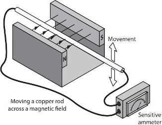
Figure 1. Inducing a current in a conductor moving within a magnetic field</div></div> <p>In the illustration above, as the conductor is moved upward, current will be induced in a direction that opposes that movement. If the conductor is then moved downward, the electromagnetic forces created will reverse. Those principles were key to the invention of the electric motor.</p> <h1>DC and Motors</h1> <p>Motors take electrical energy and convert it into mechanical energy. They can operate on either DC or AC. Small DC motors are used in tools, toys, and appliances. Examples of larger DC motors currently in use are for the propulsion of electric vehicles, in elevators and hoists, and in drives for steel rolling mills. A DC motor is made up of:</p> <ul><li>a casing containing a stator with permanent magnets (the stationary part of the motor)</li> <li>a shaft protruding from one end to which gears, pulleys and fan blades can be attached</li> <li>laminated discs containing at least three coils of wire that are attached to the shaft</li> <li>a commutator on the shaft’s end with split rings that connect the coils to brushes, and</li> <li>external terminals that are attached to the brushes.</li> </ul> <p>When an external circuit is closed and DC voltage is applied to the terminals at the end of the motor, current flows through the brushes into the coils, known as “windings”, and sets up or “induces” a magnetic field around them. The magnetic field induced in the windings will be attracted and repelled by the permanent north and south magnetic fields within the stator, and the shaft will begin to rotate. The split rings of the commutator in contact with the brushes causes a reversal of the polarities within the windings as the armature passes a certain point and this maintains the rotation of the armature. If not for the split ring commutator, the motor would reach a point where there is no longer an attraction or repulsion of magnetic forces and rotation would stop. The more sets of coils there are in the armature, the smoother the rotation will be, and the less likely that the motor will stall or lock up when it reaches that state of equilibrium just mentioned. The diagram below shows the internal components of a DC motor, with the shaft and casing omitted for clarity.</p> <div class="wp-caption aligncenter" id="attachment_42" aria-describedby="caption-attachment-42" style="width: 350px"><img class="wp-image-42 size-full" src="https://opentextbc.ca/plumbing4e/wp-content/uploads/sites/465/2024/08/Figure-3-DC-motor-components.png" alt="A simplified labeled diagram of a DC motor, focusing on its internal components (excluding the shaft and casing). The diagram highlights key elements essential to the motor’s operation. These include the split-ring commutator, which periodically reverses the current direction to maintain continuous rotation, and a brush, which delivers electrical contact to the rotating commutator. The rotor features four labeled coils (windings) that generate a magnetic field when current flows through them. Surrounding the rotor are the North and South stator magnets, which create a stationary magnetic field that interacts with the rotor’s field, producing motion." width="350" height="264" srcset="https://opentextbc.ca/plumbing4e/wp-content/uploads/sites/465/2024/08/Figure-3-DC-motor-components.png 350w, https://opentextbc.ca/plumbing4e/wp-content/uploads/sites/465/2024/08/Figure-3-DC-motor-components-300x226.png 300w, https://opentextbc.ca/plumbing4e/wp-content/uploads/sites/465/2024/08/Figure-3-DC-motor-components-65x49.png 65w, https://opentextbc.ca/plumbing4e/wp-content/uploads/sites/465/2024/08/Figure-3-DC-motor-components-225x170.png 225w" sizes="auto, (max-width: 350px) 100vw, 350px" title="" /><div class="wp-caption-text" id="caption-attachment-42">
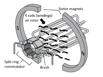
Figure 2. DC motor components</div></div> <p>For a better understanding of motors and electrical principles, check out the excellent information in some of “The Engineering Mindset” videos. Here are links to a few of them.</p> <ul><li>Alternating Current Basics: <em><a href="https://www.youtube.com/watch?v=1AaUK6pT_cE&amp;list=RDCMUCk0fGHsCEzGig-rSzkfCjMw&amp;index=6" data-url="https://www.youtube.com/watch?v=1AaUK6pT_cE&amp;list=RDCMUCk0fGHsCEzGig-rSzkfCjMw&amp;index=6">How does an Electric Motor work? (DC Motor) [4:49]</a></em></li> <li>AC and DC Electricity: <em><a href="https://www.youtube.com/watch?v=2jqJZxxX6gQ&amp;list=RDCMUCk0fGHsCEzGig-rSzkfCjMw&amp;index=7" data-url="https://www.youtube.com/watch?v=2jqJZxxX6gQ&amp;list=RDCMUCk0fGHsCEzGig-rSzkfCjMw&amp;index=7">AC and DC Electricity basics [2:56]</a></em></li> <li>How DC Motors Work: <a href="https://www.youtube.com/watch?v=1AaUK6pT_cE&amp;list=RDCMUCk0fGHsCEzGig-rSzkfCjMw&amp;index=6" data-url="https://www.youtube.com/watch?v=1AaUK6pT_cE&amp;list=RDCMUCk0fGHsCEzGig-rSzkfCjMw&amp;index=6"><em>How does an Electric Motor work? (DC Motor) [4:49]</em></a></li> <li>Induction Motors: <a href="https://www.youtube.com/watch?v=AOC7uTnxmTI" data-url="https://www.youtube.com/watch?v=AOC7uTnxmTI"><em>Induction Motor Basics [8:38]</em></a></li> <li>How 3-phase Electricity Works: <a href="https://youtu.be/4oRT7PoXSS0?si=A_X1n-_UUQyg15nJ" data-url="https://youtu.be/4oRT7PoXSS0?si=A_X1n-_UUQyg15nJ"><em>How Three Phase Electricity works – The basics explained [7:52]</em></a> (originally linked: <em><a href="https://www.youtube.com/watch?v=2jqJZxxX6gQ&amp;list=RDCMUCk0fGHsCEzGig-rSzkfCjMw&amp;index=7" data-url="https://www.youtube.com/watch?v=2jqJZxxX6gQ&amp;list=RDCMUCk0fGHsCEzGig-rSzkfCjMw&amp;index=7">AC and DC Electricity basics [2:56]</a></em>)</li> <li>Main electrical panel explained: <a href="https://youtu.be/UBERduCp3Wo" data-url="https://youtu.be/UBERduCp3Wo"><em>Main electrical panel explained – Load center – service panel [10:18]</em></a></li> </ul> <p>Before we move on to AC motors, let’s quickly recap the operation of a DC motor. The permanent magnet is fixed in place and forms the outside static part of the motor (the stator), while coils of wire carrying the electric current fed to the motor form the rotating part of the motor (the rotor). The interaction between the permanent magnetic field of the stator and the attraction/repulsion tendencies of the temporary magnetic fields produced by the windings within the rotor is what makes the motor start to spin, and the split-ring commutator changes the polarity of the incoming DC every half rotation which keeps it spinning.</p> <div class="wp-caption aligncenter" id="attachment_43" aria-describedby="caption-attachment-43" style="width: 262px"><img class="wp-image-43 size-full" src="https://opentextbc.ca/plumbing4e/wp-content/uploads/sites/465/2024/08/Figure-4-Another-simplified-view-of-a-DC-motor.png" alt="A simplified labelled diagram of a DC motor. The permanent magnet has north and south poles, called field poles. The armature is a coil of wire that rotates counterclockwise between the field poles. The ends of the armature connected to the commutator." width="262" height="202" srcset="https://opentextbc.ca/plumbing4e/wp-content/uploads/sites/465/2024/08/Figure-4-Another-simplified-view-of-a-DC-motor.png 262w, https://opentextbc.ca/plumbing4e/wp-content/uploads/sites/465/2024/08/Figure-4-Another-simplified-view-of-a-DC-motor-65x50.png 65w, https://opentextbc.ca/plumbing4e/wp-content/uploads/sites/465/2024/08/Figure-4-Another-simplified-view-of-a-DC-motor-225x173.png 225w" sizes="auto, (max-width: 262px) 100vw, 262px" title="" /><div class="wp-caption-text" id="caption-attachment-43">
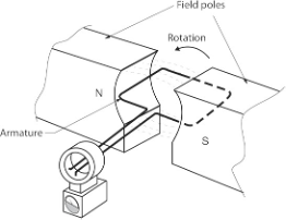
Figure 3. Another simplified view of a DC motor</div></div> <p>In the interests of adherence to the program outline for the piping trades, we will limit any further study to the basics of AC motors.</p> <h1>AC Motors</h1> <p>In an AC motor, windings are arranged around the inside of the casing (the stator), which are designed to produce a rotating magnetic field. Centred within the stator is a solid metal shaft onto which is affixed a conductor (a loop of wire or a coil), a cage made of metal bars, and interconnections between and within them, which makes up a freely rotating metal part (the rotor) that can conduct electricity and become a temporary magnet. Unlike in a DC motor, where power is sent to the coils in the rotor, in an AC motor the outer coils that make up the stator receive the electrical power. The coils are energized in pairs, in sequence, producing a strong magnetic field that is in constant movement around the outside of the motor.</p> <div class="wp-caption aligncenter" id="attachment_45" aria-describedby="caption-attachment-45" style="width: 600px"><img class="wp-image-45" src="https://opentextbc.ca/plumbing4e/wp-content/uploads/sites/465/2024/08/Figure-5-Stator-and-rotor-of-an-AC-motor-e1732053560335.png" alt="A stator (left) and rotor (right)." width="600" height="328" srcset="https://opentextbc.ca/plumbing4e/wp-content/uploads/sites/465/2024/08/Figure-5-Stator-and-rotor-of-an-AC-motor-e1732053560335.png 806w, https://opentextbc.ca/plumbing4e/wp-content/uploads/sites/465/2024/08/Figure-5-Stator-and-rotor-of-an-AC-motor-e1732053560335-300x164.png 300w, https://opentextbc.ca/plumbing4e/wp-content/uploads/sites/465/2024/08/Figure-5-Stator-and-rotor-of-an-AC-motor-e1732053560335-768x420.png 768w, https://opentextbc.ca/plumbing4e/wp-content/uploads/sites/465/2024/08/Figure-5-Stator-and-rotor-of-an-AC-motor-e1732053560335-65x36.png 65w, https://opentextbc.ca/plumbing4e/wp-content/uploads/sites/465/2024/08/Figure-5-Stator-and-rotor-of-an-AC-motor-e1732053560335-225x123.png 225w, https://opentextbc.ca/plumbing4e/wp-content/uploads/sites/465/2024/08/Figure-5-Stator-and-rotor-of-an-AC-motor-e1732053560335-350x192.png 350w" sizes="auto, (max-width: 600px) 100vw, 600px" title="" /><div class="wp-caption-text" id="caption-attachment-45">
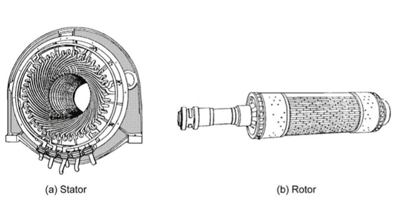
Figure 4. Stator and rotor of an AC motor</div></div> <div class="wp-caption aligncenter" id="attachment_44" aria-describedby="caption-attachment-44" style="width: 600px"><img class="wp-image-44" src="https://opentextbc.ca/plumbing4e/wp-content/uploads/sites/465/2024/08/Figure-5-Side-and-end-views-of-an-AC-rotor-1024x376.png" alt="A slide view of an AC rotor (left) and end view of an AC rotor (right)." width="600" height="220" srcset="https://opentextbc.ca/plumbing4e/wp-content/uploads/sites/465/2024/08/Figure-5-Side-and-end-views-of-an-AC-rotor-1024x376.png 1024w, https://opentextbc.ca/plumbing4e/wp-content/uploads/sites/465/2024/08/Figure-5-Side-and-end-views-of-an-AC-rotor-300x110.png 300w, https://opentextbc.ca/plumbing4e/wp-content/uploads/sites/465/2024/08/Figure-5-Side-and-end-views-of-an-AC-rotor-768x282.png 768w, https://opentextbc.ca/plumbing4e/wp-content/uploads/sites/465/2024/08/Figure-5-Side-and-end-views-of-an-AC-rotor-65x24.png 65w, https://opentextbc.ca/plumbing4e/wp-content/uploads/sites/465/2024/08/Figure-5-Side-and-end-views-of-an-AC-rotor-225x83.png 225w, https://opentextbc.ca/plumbing4e/wp-content/uploads/sites/465/2024/08/Figure-5-Side-and-end-views-of-an-AC-rotor-350x128.png 350w, https://opentextbc.ca/plumbing4e/wp-content/uploads/sites/465/2024/08/Figure-5-Side-and-end-views-of-an-AC-rotor.png 1264w" sizes="auto, (max-width: 600px) 100vw, 600px" title="" /><div class="wp-caption-text" id="caption-attachment-44">
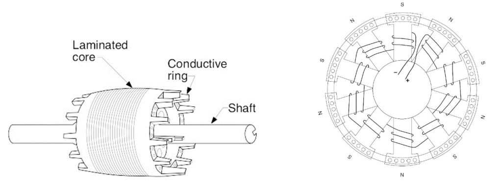
Figure 5. Side and end views of an AC rotor</div></div> <p>Remember that the rotor, suspended on bearings or bushings inside the magnetic field, is an electrical conductor. The stator’s magnetic field, fed with alternating current, is constantly changing so, according to the laws of electromagnetism, the magnetic field induces an electric current inside the rotor. The current induced in the rotor produces its own magnetic field and, according to another law of electromagnetism (Lenz’s Law) tries to stop whatever it is that causes it (the rotating magnetic field) by rotating as well. You can think of the rotor as frantically trying to “catch up” with the rotating magnetic field in an effort to eliminate the difference in motion between them. Electromagnetic induction is the key to why a motor spins, and that’s why it’s called an induction motor.</p> <h1>3-Phase Power</h1> <p>To understand three-phase motors, it is useful to first understand three-phase power.</p> <p>In electrical power generation, electricity is produced by using a power source such as water or steam in a turbine to spin a generator that is similar in its components to an electric motor, although much more massive in size. The generator’s size and number of windings create alternating current which changes in amplitude and frequency over time. If shown graphically with the amplitude on the vertical y-axis and time on the horizontal x-axis, the relationship between the voltage or current vs. time for one set of windings (a “phase”), through one complete rotation or “cycle” of the armature (rotor) would resemble a sinusoidal or “sine” wave as shown below.</p> <div class="wp-caption aligncenter" id="attachment_46" aria-describedby="caption-attachment-46" style="width: 487px"><img class="wp-image-46 size-full" src="https://opentextbc.ca/plumbing4e/wp-content/uploads/sites/465/2024/08/Figure-7-Sine-wave-of-single-phase-alternating-current-and-rotor-position-in-time.png" alt="A graph depicting the single phase of a sine wave and the corresponding rotor position. The X axis is the degrees of rotor rotation and the Y axis is the volts. The sine wave is at 0 volts at 0 degrees, maximum positive volts at 90 degrees, 0 volts at 180 degrees, maximum negative volts at 270 degrees, and 0 volts at 360 degrees. The rotor rotation starts with the South pole on the left and North pole on the right at 0 degrees of rotation. At 90 degrees, the south pole is on the top and north pole is on the bottom. At 180 degrees, the south pole is on the right and the north pole is on the left. At 270 degrees, the south pole is on the bottom and north pole is on the top. At 360 degrees, the south pole is on the left and the north pole is on the right." width="487" height="379" srcset="https://opentextbc.ca/plumbing4e/wp-content/uploads/sites/465/2024/08/Figure-7-Sine-wave-of-single-phase-alternating-current-and-rotor-position-in-time.png 487w, https://opentextbc.ca/plumbing4e/wp-content/uploads/sites/465/2024/08/Figure-7-Sine-wave-of-single-phase-alternating-current-and-rotor-position-in-time-300x233.png 300w, https://opentextbc.ca/plumbing4e/wp-content/uploads/sites/465/2024/08/Figure-7-Sine-wave-of-single-phase-alternating-current-and-rotor-position-in-time-65x51.png 65w, https://opentextbc.ca/plumbing4e/wp-content/uploads/sites/465/2024/08/Figure-7-Sine-wave-of-single-phase-alternating-current-and-rotor-position-in-time-225x175.png 225w, https://opentextbc.ca/plumbing4e/wp-content/uploads/sites/465/2024/08/Figure-7-Sine-wave-of-single-phase-alternating-current-and-rotor-position-in-time-350x272.png 350w" sizes="auto, (max-width: 487px) 100vw, 487px" title="" /><div class="wp-caption-text" id="caption-attachment-46">
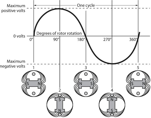
Figure 6. Sine wave of single phase alternating current and rotor position in time</div></div> <p>The graph shown above is the result of one set of windings rotating 360 degrees creating alternating current. Add another 2 sets of windings on the same spinning armature and there will be 3 alternating currents or phases produced simultaneously. If the windings are spaced evenly around the armature, their sine waves will be 120 degrees apart as well.&nbsp; There is nothing magical about three-phase power. It is simply three single phases synchronized and offset by 120 degrees. The diagram below shows the effect of the three sets of windings spinning on the same armature (top illustration) and each of the three windings or “phases” shown by themselves below it.</p> <div class="wp-caption aligncenter" id="attachment_334" aria-describedby="caption-attachment-334" style="width: 503px"><img class="wp-image-334" src="https://opentextbc.ca/plumbing4e/wp-content/uploads/sites/465/2024/08/Sine-waves.png" alt="Four graphs depict a 3-phase sine wave, and the three different phases separated out. On the first graph, all three sine waves are on one graph. The sine waves are offset by 120 degrees so that the phases are evenly spaced and peak at different times. The second graph depicts the first sine wave alone, coloured in red, and with a phase of 0. The third graph depicts the second sine wave alone, coloured in blue, and with a phase of +120 degrees. And the fourth graph depicts the third phase alone, coloured in green, and with a phase of –120 degrees." width="503" height="687" srcset="https://opentextbc.ca/plumbing4e/wp-content/uploads/sites/465/2024/08/Sine-waves.png 2711w, https://opentextbc.ca/plumbing4e/wp-content/uploads/sites/465/2024/08/Sine-waves-220x300.png 220w, https://opentextbc.ca/plumbing4e/wp-content/uploads/sites/465/2024/08/Sine-waves-750x1024.png 750w, https://opentextbc.ca/plumbing4e/wp-content/uploads/sites/465/2024/08/Sine-waves-768x1049.png 768w, https://opentextbc.ca/plumbing4e/wp-content/uploads/sites/465/2024/08/Sine-waves-1125x1536.png 1125w, https://opentextbc.ca/plumbing4e/wp-content/uploads/sites/465/2024/08/Sine-waves-1500x2048.png 1500w, https://opentextbc.ca/plumbing4e/wp-content/uploads/sites/465/2024/08/Sine-waves-65x89.png 65w, https://opentextbc.ca/plumbing4e/wp-content/uploads/sites/465/2024/08/Sine-waves-225x307.png 225w, https://opentextbc.ca/plumbing4e/wp-content/uploads/sites/465/2024/08/Sine-waves-350x478.png 350w" sizes="auto, (max-width: 503px) 100vw, 503px" title="" /><div class="wp-caption-text" id="caption-attachment-334">
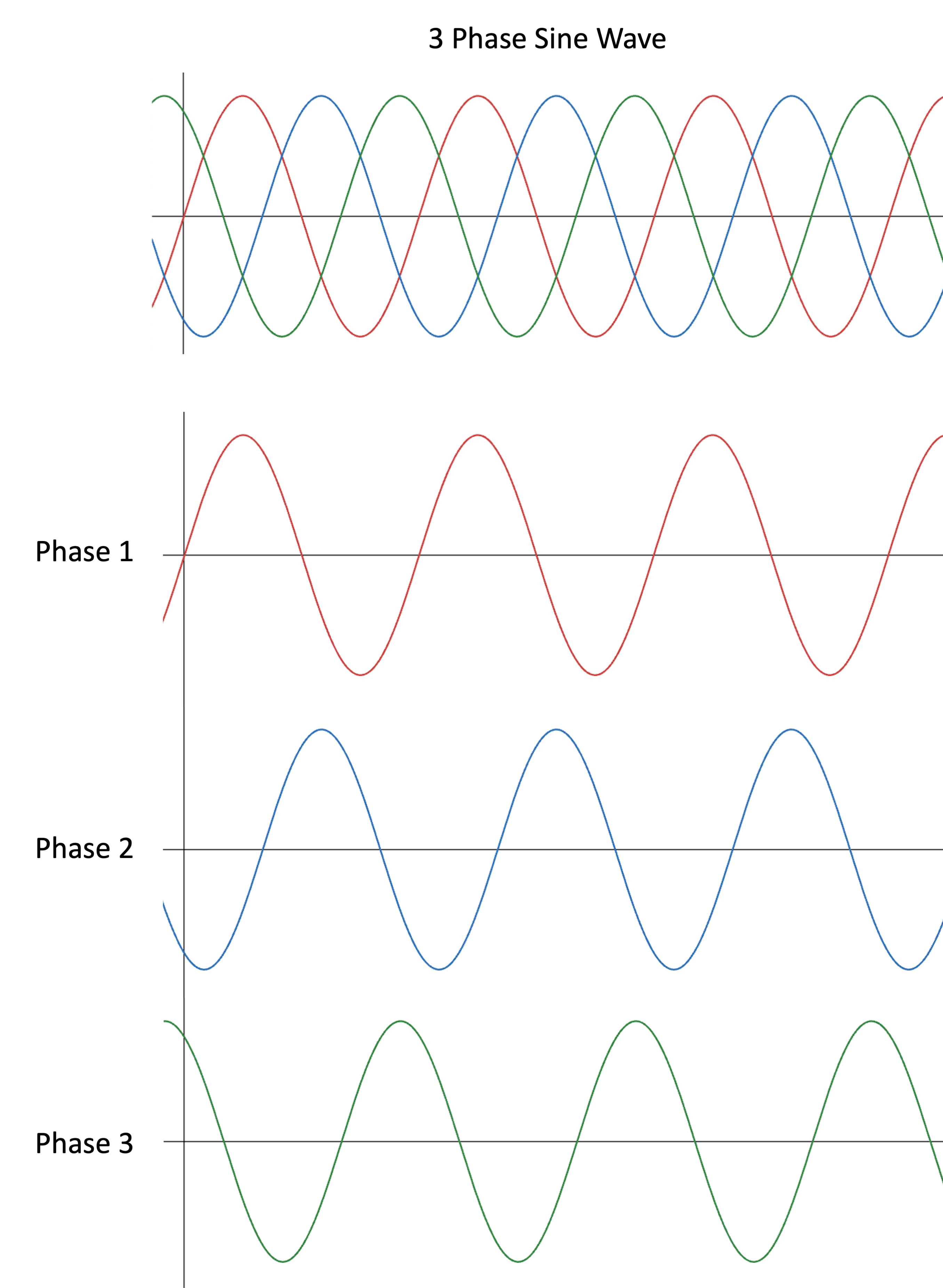
Figure 7. Graph showing sine waves of 3-phase alternating current over time, and individual phases within it</div></div> <p>The three-phase alternating current leaves the generator and enters a transmission substation at the power plant where large transformers convert the generator’s voltage (which is already at the thousands of volts level) up to extremely high voltages for long-distance transmission on the power transmission grid. Typical voltages for long distance transmission are in the range of 155<span style="margin-left: 0.25em;">000</span> to 765<span style="margin-left: 0.25em;">000</span> volts to reduce line losses. The extremely high voltages are stepped down at distribution stations by transformers and are then fed to different areas surrounding the station at a voltage value somewhere around 7200 volts AC. 3-phase AC electricity is confined in its use to commercial and industrial areas where more power is needed to operate large motors and heaters, so transformers will often reduce the voltage in these applications to around 600 volts of 3-phase power. 3-phase transformers for&nbsp; commercial buildings may be of lower output voltages such as 480 and 400 volts.</p> <p>The 3-phase power can be of either a Delta or a Wye configuration. These terms refer to the way the three secondary coils of the transformer secondary have been connected.</p> <div class="wp-caption aligncenter" id="attachment_48" aria-describedby="caption-attachment-48" style="width: 763px"><img class="wp-image-48 size-full" src="https://opentextbc.ca/plumbing4e/wp-content/uploads/sites/465/2024/08/Figure-9-3-phase-Delta-wiring.png" alt="A labeled diagram of a 3-phase Delta wiring. There are three phases and the voltage relationships between all of them are 240 Volts. There are three line currents A, B, and C and they form a triangle." width="763" height="574" srcset="https://opentextbc.ca/plumbing4e/wp-content/uploads/sites/465/2024/08/Figure-9-3-phase-Delta-wiring.png 763w, https://opentextbc.ca/plumbing4e/wp-content/uploads/sites/465/2024/08/Figure-9-3-phase-Delta-wiring-300x226.png 300w, https://opentextbc.ca/plumbing4e/wp-content/uploads/sites/465/2024/08/Figure-9-3-phase-Delta-wiring-65x49.png 65w, https://opentextbc.ca/plumbing4e/wp-content/uploads/sites/465/2024/08/Figure-9-3-phase-Delta-wiring-225x169.png 225w, https://opentextbc.ca/plumbing4e/wp-content/uploads/sites/465/2024/08/Figure-9-3-phase-Delta-wiring-350x263.png 350w" sizes="auto, (max-width: 763px) 100vw, 763px" title="" /><div class="wp-caption-text" id="caption-attachment-48">
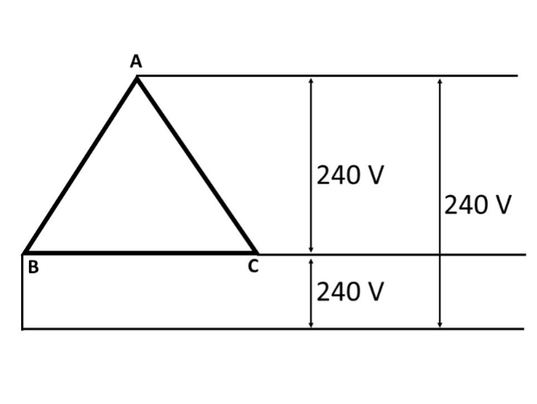
Figure 8. 3-phase Delta wiring</div></div> <p>3-phase Delta systems are normally used for powering loads that don’t require a neutral, such as large motors or heaters. Generation plants typically send power out through this configuration as there is no need for the expense of a fourth neutral wire over what may be very long distances.</p> <p>
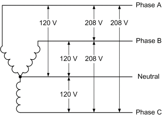
Distribution transformer secondarys are wired either as Delta or Wye configurations, again usually being determined by the intended uses of the power. The advantage of a Wye configuration is that, with the fourth wire (neutral) it allows the transformer to deliver power for both single-phase as well as 3-phase loads. Note that in the 3-phase Wye diagram below, the line-to-neutral (hot-to-neutral) voltages are all at 120 volts, but the line-to-line (hot-to-hot) voltages are 208 volts. This is because of the phases being 120° apart, where, if one of the phases is at peak voltage, the other line isn’t. If two hot lines were 180° apart, as they are in 120 volt split-phase residential systems, the line voltage is added together to result in 240 volts, which powers appliances such as clothes dryers, ranges, and hot water tanks. Combining two hot 120-volt phases in a 3-phase system results in 208 volts, which is 120 volts × 1.732 (the square root of 3 which represents the two phases being 120° apart). The explanations and calculations that would be used to illustrate that phenomenon are best left to another time and trade.<a id="e2fig9" data-url=""></a></p> <div class="wp-caption aligncenter" id="attachment_49" aria-describedby="caption-attachment-49" style="width: 579px"><img class="wp-image-49 size-full" src="https://opentextbc.ca/plumbing4e/wp-content/uploads/sites/465/2024/08/Figure-10-3-phase-Wye-wiring.png" alt="A labeled diagram of 3-phase wye wiring. Image description is available." width="579" height="408" srcset="https://opentextbc.ca/plumbing4e/wp-content/uploads/sites/465/2024/08/Figure-10-3-phase-Wye-wiring.png 579w, https://opentextbc.ca/plumbing4e/wp-content/uploads/sites/465/2024/08/Figure-10-3-phase-Wye-wiring-300x211.png 300w, https://opentextbc.ca/plumbing4e/wp-content/uploads/sites/465/2024/08/Figure-10-3-phase-Wye-wiring-65x46.png 65w, https://opentextbc.ca/plumbing4e/wp-content/uploads/sites/465/2024/08/Figure-10-3-phase-Wye-wiring-225x159.png 225w, https://opentextbc.ca/plumbing4e/wp-content/uploads/sites/465/2024/08/Figure-10-3-phase-Wye-wiring-350x247.png 350w" sizes="auto, (max-width: 579px) 100vw, 579px" title="" /><div class="wp-caption-text" id="caption-attachment-49">Figure 9. 3-phase Wye wiring <a href="#e2fig10_desc" data-url="https://opentextbc.ca/plumbing4e/chapter/describe-electric-motors/#e2fig10_desc"><em>[Image Description]</em></a></div></div> <h1>Split-Phase Power</h1> <p>For safety’s sake, and due to the absence of motors and other loads that would require a higher and more efficient power supply, houses aren’t fed with 3-phase power. The transformers at the street will step one leg or phase of the incoming power down to 240 volts and will tap a neutral into the middle of the secondary coil. This delivers two 120-volt hot wires that are 180° out-of-phase from each other and a neutral to the house, as shown in the diagram below.</p> <div class="wp-caption aligncenter" id="attachment_50" aria-describedby="caption-attachment-50" style="width: 246px"><img class="wp-image-50 size-full" src="https://opentextbc.ca/plumbing4e/wp-content/uploads/sites/465/2024/08/Figure-11-Split-phase-power-to-residential-buildings.png" alt="A labelled diagram of a split-phase power to residential buildings, the transformers outside of your home. There are three lines: Line 1 (top), Neutral line (middle), and Line 2 (bottom). The volts between Line 1 and the neutral line are 120 Volts, the volts between the neutral line are 120 volts, and the volts between Line 1 and 2 are 240 volts." width="246" height="141" srcset="https://opentextbc.ca/plumbing4e/wp-content/uploads/sites/465/2024/08/Figure-11-Split-phase-power-to-residential-buildings.png 246w, https://opentextbc.ca/plumbing4e/wp-content/uploads/sites/465/2024/08/Figure-11-Split-phase-power-to-residential-buildings-65x37.png 65w, https://opentextbc.ca/plumbing4e/wp-content/uploads/sites/465/2024/08/Figure-11-Split-phase-power-to-residential-buildings-225x129.png 225w" sizes="auto, (max-width: 246px) 100vw, 246px" title="" /><div class="wp-caption-text" id="caption-attachment-50">
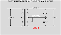
Figure 10. Split-phase power to residential buildings</div></div> <p>When the two hot legs (Line 1 and Line 2) are wired to an appliance, the voltage difference between them is 240 volts (+120 minus -120 = 240). Electric hot water tanks are wired with just the two hot leads and no neutral because there is no need for a 120V control circuit. Electric dryers and ranges have their 120V control circuits powered by tapping into one of the 120V hot legs and providing a return path to the panel via the neutral wire, so they are 3-wire circuits (two 120-volt hots and a neutral). A common house panel is shown below. The bus connections are staggered, so any two adjacent breakers will be in contact with the L1 and L2 (main) buses. If both breakers feed an appliance, such as through the red and black wires on the right side of the panel, it will be supplied with 240 volts. The switch levers of the two breakers must be tied together so they operate as one.</p> <div class="wp-caption aligncenter" id="attachment_51" aria-describedby="caption-attachment-51" style="width: 446px"><img class="wp-image-51 size-full" src="https://opentextbc.ca/plumbing4e/wp-content/uploads/sites/465/2024/08/Figure-12-House-Panel.jpg" alt="A house panel with the components labelled. The components are: The ground wire, line 1 (black wire, +120 volts), line 2 (red wire, -120 volts), the neutral line (grey wire), main breaker, neutral busses, and main busses." width="446" height="336" srcset="https://opentextbc.ca/plumbing4e/wp-content/uploads/sites/465/2024/08/Figure-12-House-Panel.jpg 446w, https://opentextbc.ca/plumbing4e/wp-content/uploads/sites/465/2024/08/Figure-12-House-Panel-300x226.jpg 300w, https://opentextbc.ca/plumbing4e/wp-content/uploads/sites/465/2024/08/Figure-12-House-Panel-65x49.jpg 65w, https://opentextbc.ca/plumbing4e/wp-content/uploads/sites/465/2024/08/Figure-12-House-Panel-225x170.jpg 225w, https://opentextbc.ca/plumbing4e/wp-content/uploads/sites/465/2024/08/Figure-12-House-Panel-350x264.jpg 350w" sizes="auto, (max-width: 446px) 100vw, 446px" title="" /><div class="wp-caption-text" id="caption-attachment-51">
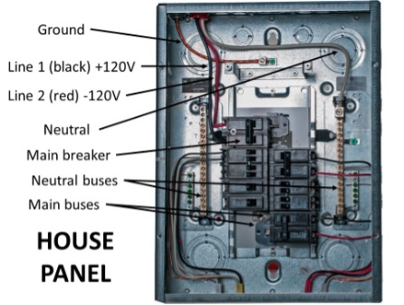
Figure 11. House Panel</div></div> <h1>Induction Motors</h1> <p>Induction motors pass an alternating current through coils in the stator which produces a magnetic field, and the oscillating frequency of the AC supply will cause this magnetic field to rotate. The rotating magnetic field (RMF) will then induce opposing magnetic fields in the rotor and cause useful rotation. Both 3-phase and single-phase use this principle, however, the magnetic field produced by 3-phase current will naturally rotate due to the phases being 120° apart. The stator in a 3-phase motor will have a minimum of 2 sets of windings for each phase, as seen in the diagram below.</p> <div class="wp-caption aligncenter" id="attachment_52" aria-describedby="caption-attachment-52" style="width: 248px"><img class="wp-image-52 size-full" src="https://opentextbc.ca/plumbing4e/wp-content/uploads/sites/465/2024/08/Figure-13-Stator-showing-3-sets-of-opposed-windings-Aa-Bb-and-Cc.png" alt="A labelled diagram of a stator with 3 sets of windings. The stator is circular with the coils of each set of windings opposite each other (“A” is opposite of “a”, “B” is opposite of “b”, “C” is opposite of “c”). It rotates in an anticlockwise direction and each rotation is 120 degrees and each phase (120-degree rotation) has a minimum of 2 windings (one rotation has windings “A” and “C”. Another rotation has windings “C” and “B”)." width="248" height="224" srcset="https://opentextbc.ca/plumbing4e/wp-content/uploads/sites/465/2024/08/Figure-13-Stator-showing-3-sets-of-opposed-windings-Aa-Bb-and-Cc.png 248w, https://opentextbc.ca/plumbing4e/wp-content/uploads/sites/465/2024/08/Figure-13-Stator-showing-3-sets-of-opposed-windings-Aa-Bb-and-Cc-65x59.png 65w, https://opentextbc.ca/plumbing4e/wp-content/uploads/sites/465/2024/08/Figure-13-Stator-showing-3-sets-of-opposed-windings-Aa-Bb-and-Cc-225x203.png 225w" sizes="auto, (max-width: 248px) 100vw, 248px" title="" /><div class="wp-caption-text" id="caption-attachment-52">
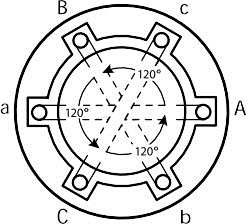
Figure 12. Stator showing 3 sets of opposed windings (Aa, Bb and Cc)</div></div> <p>The coils are on opposite sides of the stator from each other so the powerful magnetic fields resulting from current flowing through them will cause induced current in the rotor and the rotor will spin. The rotor’s direction of rotation can be reversed by reversing the positions of any two of the three incoming power legs on their terminal connections.</p> <h1>Single-Phase Motors</h1> <p>The single-phase induction motor is a popular motor with the advantages of being cheap, reliable, and able to connect directly to single-phase power, making them especially common in domestic and small commercial appliances. However, unlike three-phase motors, they are not self-starting and require an additional winding driven by a capacitor to accelerate from a standstill. For an induction motor to start running, a rotating magnetic field (RMF) must be produced in the stator, which induces rotation and torque in the rotor. Since the stator does not physically move, the rotation of the magnetic field is produced by the interaction between electromagnetic forces produced in the stator windings. In a three-phase motor, with each winding supplied by a voltage that is 120 degrees out of phase with the other windings, the sum of the forces produced creates a rotating magnetic field (RMF). This means that three-phase power can induce torque in the rotor at a standstill, and three-phase motors can self-start without additional components.</p> <p>However, a single-phase induction motor is fed by a single-phase power supply that runs through a single stator winding. One stator winding on its own cannot produce an RMF – it merely produces a pulsing magnetic field that is made of two opposing fields spaced 180 degrees apart. This creates two problems:</p> <ul><li>first, the motor is not self-starting because the magnetic field produced by the stator is not rotating; and</li> <li>secondly, although a single winding can drive the motor once it gets up to speed, it does not produce a consistent torque in the rotor during a full revolution, which leads to a loss of efficiency and performance.</li> </ul> <p>The rotor experiences maximum torque at approximately 10% slip (the difference in rotation between the rotor and the stator winding). Therefore, the rotor will spend a large part of each revolution experiencing very low torque.</p> <h2>Auxiliary Winding</h2> <p>In addition to the “run” windings within the stator, single-phase induction motors use a second stator winding to overcome these problems, called an ‘auxiliary winding’ or ‘start winding.’ This winding is rotated 90 degrees away from the main winding, and, by means of a capacitor that changes the phase of the supply voltage, it is fed by a voltage that is out of phase with the voltage supplied to the main winding. This means that the interaction between the two windings produces a rotating magnetic field, and the motor can self-start.</p> <p>There are two capacitors with different characteristics used by single-phase induction motors for different aspects of their operation.</p> <h2>Start Capacitors</h2> <p>A start capacitor is one that is used to provide starting torque to the motor. They are electrolytic capacitors with relatively high losses and low efficiency and are not designed for continuous duty, so it is necessary to disconnect them once the motor gets up to speed using a centrifugal switch or relay of some kind.</p> <div class="wp-caption aligncenter" id="attachment_53" aria-describedby="caption-attachment-53" style="width: 400px"><img class="wp-image-53" src="https://opentextbc.ca/plumbing4e/wp-content/uploads/sites/465/2024/08/Figure-14-Start-left-and-run-right-capacitors.png" alt="A start capacitor and a run capacitor. The start capacitor is a TemCo SC0131 Round Motor Start Capacitor. The run capacitor is a Titan pro 370 motor run capacitor." width="400" height="280" srcset="https://opentextbc.ca/plumbing4e/wp-content/uploads/sites/465/2024/08/Figure-14-Start-left-and-run-right-capacitors.png 838w, https://opentextbc.ca/plumbing4e/wp-content/uploads/sites/465/2024/08/Figure-14-Start-left-and-run-right-capacitors-300x210.png 300w, https://opentextbc.ca/plumbing4e/wp-content/uploads/sites/465/2024/08/Figure-14-Start-left-and-run-right-capacitors-768x537.png 768w, https://opentextbc.ca/plumbing4e/wp-content/uploads/sites/465/2024/08/Figure-14-Start-left-and-run-right-capacitors-65x45.png 65w, https://opentextbc.ca/plumbing4e/wp-content/uploads/sites/465/2024/08/Figure-14-Start-left-and-run-right-capacitors-225x157.png 225w, https://opentextbc.ca/plumbing4e/wp-content/uploads/sites/465/2024/08/Figure-14-Start-left-and-run-right-capacitors-350x245.png 350w" sizes="auto, (max-width: 400px) 100vw, 400px" title="" /><div class="wp-caption-text" id="caption-attachment-53">
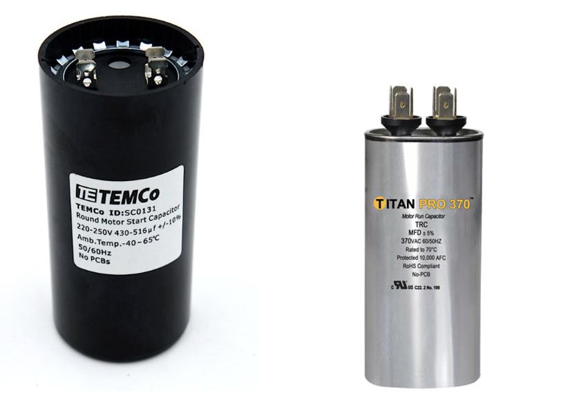
Figure 13. Start (left) and run (right) capacitors</div></div> <p>The flyweights in the centrifugal switch shown below move outward from the shaft and, in doing so, move the collar to which they are attached to the right. This breaks the contacts between the line voltage and the start capacitor of the auxiliary winding. This happens at approximately 75% of the motor’s rated speed.</p> <p>&nbsp;</p> <div class="wp-caption aligncenter" id="attachment_54" aria-describedby="caption-attachment-54" style="width: 312px"><img class="wp-image-54 size-full" src="https://opentextbc.ca/plumbing4e/wp-content/uploads/sites/465/2024/08/Figure-15-Centrifugal-switch.png" alt="A labelled diagram of a centrifugal switch. The components are the rotor, two flyweights, the collar, and the switch contacts (one to the line, one to the auxiliary winding). The flyweights move back and forth from the rotor shaft, which causes the collar to move right to left. This then pushes the switch contacts and breaks them." width="312" height="228" srcset="https://opentextbc.ca/plumbing4e/wp-content/uploads/sites/465/2024/08/Figure-15-Centrifugal-switch.png 312w, https://opentextbc.ca/plumbing4e/wp-content/uploads/sites/465/2024/08/Figure-15-Centrifugal-switch-300x219.png 300w, https://opentextbc.ca/plumbing4e/wp-content/uploads/sites/465/2024/08/Figure-15-Centrifugal-switch-65x48.png 65w, https://opentextbc.ca/plumbing4e/wp-content/uploads/sites/465/2024/08/Figure-15-Centrifugal-switch-225x164.png 225w" sizes="auto, (max-width: 312px) 100vw, 312px" title="" /><div class="wp-caption-text" id="caption-attachment-54">
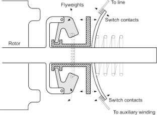
Figure 14. Centrifugal switch</div></div> <h2>Run Capacitors</h2> <p>A run capacitor is used to smooth the motor’s torque during each revolution, increasing efficiency and performance. It is usually much smaller than a start capacitor and of the oil-filled type to reduce energy losses.</p> <h2>Limitations of Single-Phase Motors</h2> <p>Even with the additional auxiliary winding, a single-phase induction motor suffers from several limitations compared to a three-phase motor. The phase shift provided by a run capacitor changes with the motor’s speed, which means efficiency is not consistent as the motor changes speed. Efficiency is also affected by RMF being produced by two stator windings. It is not as close to a perfect circle as a three-phase RMF, meaning that torque still varies considerably during each revolution, reducing performance and increasing vibration. The components required to make single-phase induction motors self-starting, including the capacitors and centrifugal switch, provide an opportunity for thermal and mechanical wear to create maintenance problems.</p> <h1>Induction Motors and “Slip”</h1> <p>Both single- and three-phase motors are also known as “asynchronous” induction motors, as the frequency of their AC current does not directly match the number of rotations of the output shaft. This phenomenon is known as “slip” and occurs because the rotor is always playing a magnetic game of “catch-up” with the RMF. The existence of slip means precise timing is difficult with induction motors. Slip is acceptable in situations where precise timing isn’t required.</p> <h1>Synchronous Motors</h1> <p>Synchronous motors cover the bases that induction motors cannot, namely their “asynchronous” nature. Synchronous motors match the output rotational frequency to the input AC frequency, allowing designers to use these motors in precisely timed applications, such as clocks, rolling mills, record players, and more. They accomplish this feat by linking the magnetic poles (the north-south pairs in every magnetic field) of the stator and rotor, so that the stator RMF will turn the rotor at exact, synchronous speeds. Synchronous motors, while generally more expensive than induction motors, sport higher efficiencies. The lack of complexity of induction motors is the best advantage that they have over synchronous designs. They are very simple to manufacture, operate, and maintain, and is why induction motors are by and large less expensive than synchronous motors. Conversely, implementing a synchronous machine requires a more complex rotor, which is more difficult to manufacture/repair, and requires additional circuits that must be bought and installed so that these motors can operate effectively.</p> <p>In some cases, synchronous motors can achieve efficiencies of &gt;90% and are generally more energy-efficient than induction motors. The efficiency depends on the specific motor type and size, but the lack of slip in synchronous motors means there is less energy lost in converting between electrical energy and mechanical energy. Finally, a common theme between synchronous motors and induction motors is their price separation. For reasons previously explained, synchronous motors are more expensive to produce, implement, maintain, and repair than induction motors, and so are less commonly used.</p> <h1>Speed Control for Motors</h1> <p>A variable frequency drive (VFD) is a type of motor controller that adjusts the speed of an electric motor by varying the frequency and voltage supplied to it. Other names for a VFD are variable speed drive, adjustable speed drive, adjustable frequency drive, AC drive, microdrive, and inverter.</p> <p>Frequency (or hertz) is directly related to the motor’s speed (RPMs). In other words, the faster the frequency, the faster the RPMs. If an application does not require an electric motor to run at full speed, the VFD can be used to ramp down the frequency and voltage to meet the requirements of the electric motor’s load. As the application’s motor speed requirements change, the VFD can simply turn up or down the motor speed to meet the speed requirement. While VFDs are the standard for speed control of 3-phase motors, slowing down single-phase motors is a more difficult task, especially if it is of the type that uses a centrifugal switch to disconnect the start windings. Always make sure to use a speed control that is recommended for a specific type of motor.</p> <h1>Motor Control</h1> <p>Small fractional horsepower single-phase motors used in residential applications are normally controlled using a simple on/off switch. Large single- and three-phase motors in commercial and industrial applications need more protection due to their relative size and cost. Combination motor controllers are normally used for these motors.</p> <div class="wp-caption aligncenter" id="attachment_55" aria-describedby="caption-attachment-55" style="width: 246px"><img class="size-full wp-image-55" src="https://opentextbc.ca/plumbing4e/wp-content/uploads/sites/465/2024/08/Figure-16-Combination-motor-control.png" alt="" width="246" height="246" srcset="https://opentextbc.ca/plumbing4e/wp-content/uploads/sites/465/2024/08/Figure-16-Combination-motor-control.png 246w, https://opentextbc.ca/plumbing4e/wp-content/uploads/sites/465/2024/08/Figure-16-Combination-motor-control-150x150.png 150w, https://opentextbc.ca/plumbing4e/wp-content/uploads/sites/465/2024/08/Figure-16-Combination-motor-control-65x65.png 65w, https://opentextbc.ca/plumbing4e/wp-content/uploads/sites/465/2024/08/Figure-16-Combination-motor-control-225x225.png 225w" sizes="auto, (max-width: 246px) 100vw, 246px" title="" /><div class="wp-caption-text" id="caption-attachment-55">
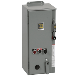
Figure 15. Combination motor control</div></div> <p>The following are the most fundamental functions that a combination motor controller performs:</p> <p><strong>On/off control:</strong> The starter controls the opening and closing of the power electrical circuit. The switching is done by the main contacts (poles) of the relay, known as a contactor. An electromagnetic coil is energized, which open or close the contacts. The electromagnetic coil has a nominal control voltage and can either be an AC or DC voltage.</p> <p><strong>Short-circuit protection:</strong> In industrial applications, normal load current can be up to thousands of amperes and in the case of a short-circuit fault, the fault current can go over 100<span style="margin-left: 0.25em;">000</span> amperes, and this can cause severe damage to the equipment. The short-circuit protection disconnects the supply and prevents the potential damage in a safe manner. Short circuit protection is provided by fuses or circuit breakers in a combination motor controller.</p> <p><strong>Overload protection:</strong> When a motor draws more current than it is designed to, an overload condition is caused. The main objective of an overload relay is to detect the excess currents and open the circuit to prevent the motor from burning out or overheating. Electronic or electromechanical overload relays are used in combination with a contactor to provide the required overload protection.</p> <p><strong>Disconnecting and breaking:</strong> To prevent an unintended restart, it is required to disconnect the motor from the main power circuit. As well, In order to safely perform maintenance on a motor or starter, a motor must be able to be isolated from the power. The disconnect switch of the circuit provides this function. Disconnecting and breaking is provided by a disconnect switch or circuit breaker in a combination motor controller.</p> <p>For an excellent online video that explains the wiring and functions of a single-phase motor starter, watch <em><a href="https://www.youtube.com/watch?v=7U-DqKQkSPU" data-url="https://www.youtube.com/watch?v=7U-DqKQkSPU">Single Phase Direct Online Starter DOL Wiring Diagram Connections Explained – AM2, AM2S, AM2E [15:24]</a></em></p> <p>Watch <a href="https://www.youtube.com/watch?v=h89TTwlNnpY" data-url="https://www.youtube.com/watch?v=h89TTwlNnpY"><em>Star Delta Starter Explained – Working Principle [11:07]</em></a>&nbsp;for an informative video on the starting controls for 3-phase motors.</p> <h1>Motor Enclosures</h1> <p>Motors have two basic types of enclosures—open and enclosed. Open enclosures allow for the free flow of air through the motor internals for cooling while those that are enclosed greatly restrict or prohibit the entry of outside air. The basic designs used in applications are described below.</p> <h2>Open Drip Proof</h2> <p>The open drip proof (ODP) enclosure is intended for installation in clean and dry environments and tends to be the standard in indoor applications. An internal fan circulates ambient air through the enclosure and provides a highly efficient cooling process.</p> <h2>Totally Enclosed Fan Cooled</h2> <p>The totally enclosed fan cooled (TEFC) enclosure is designed for outdoor installation and dirty or dusty indoor applications. Special TEFC designs are also used in processing plants in which periodic wash down is required. Unlike the ODP enclosure, it uses an external fan to force ambient air over the motor’s exterior surface.</p> <h2>Totally Enclosed Air Over</h2> <p>The totally Enclosed Air Over (TEAO) enclosure is designed for damp or wet environments in which the driven machine provides the air flow required for cooling. A common application is cooling tower fans. TEAO motors often have multiple horsepower ratings, and the usable horsepower depends upon the velocity and temperature of the air flowing over the motor.</p> <h2>Totally Enclosed Non-Ventilated</h2> <p>The totally enclosed non-ventilated (TENV) enclosure is designed for dusty environments and is usually limited to 5 horsepower and less. It uses raised fins over the motor surface area to transfer heat to the surrounding air without the aid of an external fan.</p> <h1>Hazardous Locations</h1> <p>Hazardous location motors are a totally enclosed design that are intended for use in potentially dangerous areas. The Class I, Explosion Proof (XP) enclosure is a special type that is designed for use in locations in which potentially explosive liquids and gases may be present. Class II enclosures are used in locations that are subject to combustible dusts, such as coal and grains. The area where the rotor shaft exits the enclosure is designed to contain any sparks that could occur inside the motor enclosure.</p> <h1>Nameplate Information</h1> <p>NEMA MG-1 requires that certain information be included on the nameplate of all single- and three-phase motors. Typical nameplate information may include, but is not limited to expressions of horsepower, volts, amps, Hz, phase, rpm, insulation class, enclosure, frame size, efficiency, service factor, power factor, duty, ambient, code and design. Most terms are straightforward but there are several that require further explanation. An example of a motor nameplate is shown below. Note that, whenever replacing a motor, a photo of its nameplate passed on to a supplier is the easiest and most advisable way to ensure replacement compatibility.</p> <div class="wp-caption aligncenter" id="attachment_56" aria-describedby="caption-attachment-56" style="width: 1024px"><img class="wp-image-56 size-large" src="https://opentextbc.ca/plumbing4e/wp-content/uploads/sites/465/2024/08/Figure-17-AC-motor-nameplate-1024x637.png" alt="An example of an AC motor nameplate. The information on the plate include: The catalog number, model number, shaft end BRG, OPP end BRG, frame designation (FR), Manufacturer’s type (TYPE), Number of phases (PH), maximum ambient temperature (max amb, degrees Celsius), ID number, insulation system designation (Insul. class), Time rating or duty (duty), WT, Horsepower output (HP), speed at rated load (RPM), service factor (SF), Frequency (HZ), Voltage (Volts) Max KVAR, NEMA nominal efficiency (NEMA NOM EFF), rate load current (AMPS), code letter for locked rotor kVA (CODE), Design letter (DES) - only for medium motors, SF AMPS, PF, and Guaranteed efficiency. “Thermally protected” (if motor provides all protection in NEMA Standard MG 1, 12.57) and “Over temp. Proto. ____” and device type number (for motors &amp;gt; 1 hp with over-temperature devices or systems). Note: nameplates may also include the manufacturer’s name and usually its principal location." width="1024" height="637" srcset="https://opentextbc.ca/plumbing4e/wp-content/uploads/sites/465/2024/08/Figure-17-AC-motor-nameplate-1024x637.png 1024w, https://opentextbc.ca/plumbing4e/wp-content/uploads/sites/465/2024/08/Figure-17-AC-motor-nameplate-300x187.png 300w, https://opentextbc.ca/plumbing4e/wp-content/uploads/sites/465/2024/08/Figure-17-AC-motor-nameplate-768x478.png 768w, https://opentextbc.ca/plumbing4e/wp-content/uploads/sites/465/2024/08/Figure-17-AC-motor-nameplate-65x40.png 65w, https://opentextbc.ca/plumbing4e/wp-content/uploads/sites/465/2024/08/Figure-17-AC-motor-nameplate-225x140.png 225w, https://opentextbc.ca/plumbing4e/wp-content/uploads/sites/465/2024/08/Figure-17-AC-motor-nameplate-350x218.png 350w, https://opentextbc.ca/plumbing4e/wp-content/uploads/sites/465/2024/08/Figure-17-AC-motor-nameplate.png 1090w" sizes="auto, (max-width: 1024px) 100vw, 1024px" title="" /><div class="wp-caption-text" id="caption-attachment-56">
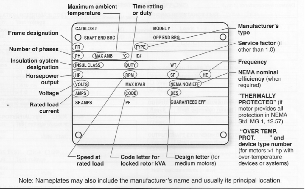
Figure 16. AC motor nameplate</div></div> <h1>Efficiency</h1> <p>Efficiency (Eff) defines how well a motor converts electrical energy into mechanical energy. The motor’s full load efficiency is shown on the nameplate, and it is often less than the actual maximum efficiency. Maximum motor efficiency typically occurs between 70 percent and 95 percent of full load, and most NEMA motors can be operated as low as 60 percent of full load without any significant loss in efficiency.</p> <h2>Service Factor</h2> <p>Service factor (SF) is a multiplier that indicates the actual horsepower that the motor can deliver over and above the nameplate horsepower. For example, if a 10-horsepower motor has an SF of 1.15, it is designed to deliver 11.5 horsepower without overloading. SF is intended to handle small, intermittent overloads, occasional increases in ambient temperature and periods when the actual voltage is lower than the nameplate voltage.</p> <h2>Power Factor</h2> <p>Power factor (PF) is the ratio of active power in watts to the apparent power in volt-amps at full load. A motor can be designed for high efficiency or high PF but not both. Since efficiency cannot be enhanced in the field, motors are designed for high efficiency and the trade-off is lower PF.</p> <h2>Duty</h2> <p>Duty defines the length of time that the motor can operate while meeting its other nameplate ratings. Most industrial motors are rated for continuous duty while certain special application motors will show intermittent run times in minutes. Electrical code definitions for duty are covered in the following section.</p> <h2>Ambient Temperature</h2> <p>Ambient temperature is the maximum allowable temperature of the air surrounding a motor when it is operated continuously at full load. A typical ambient rating is 40 °C (104°F).</p> <h2>Code Letters</h2> <p>Code letters (A – V) provide the range of current required (locked rotor current or LRC) during across-the-line starting for a particular motor. The value indicated by the code letter is in units of KVA/horsepower. A typical industrial motor will require five to seven times the full load current during starting.</p> <h2>Design Letters</h2> <p>Design letters (A-D) indicate the shape of the torque curve produced by a particular motor. Design B is the standard for industrial duty motors, Design C provides a higher starting torque while Design D is a high slip motor that provides the highest starting torque. Design A is a special purpose motor that offers the highest pullout torque.</p> <p><img class="wp-image-56 alignleft" src="https://pressbooks.bccampus.ca/plumbing3e/wp-content/uploads/sites/1587/2022/01/noun-check-702756.png" alt="" width="50" height="50" title="" />Now complete Self-Test 2 and check your answers.</p> <p>&nbsp;</p> <h1>Self-Test 2</h1> <div class="textbox textbox--exercises"><div class="textbox__header"><p class="textbox__title">Self-Test 2</p> </div> <div class="textbox__content"><div class="textbox interactive-content"><span class="interactive-content__icon"></span> <p>An interactive H5P element has been excluded from this version of the text. You can view it online here:<br /> <a href="https://opentextbc.ca/plumbing4e/?p=83#h5p-4" title="E2 Self-Test 4" data-url="https://opentextbc.ca/plumbing4e/?p=83#h5p-4">https://opentextbc.ca/plumbing4e/?p=83#h5p-4</a> </p> </div> </div> </div> <h1>Media Attributions</h1> <ul><li>Figure 1. “Inducing a current in a conductor moving within a magnetic field” ©SkilledTradesBC, Province of British Columbia. These resources are not designed for rework, reuse, remixing, and/or redistribution; they are to be used solely for the purposes of instruction.</li> <li>Figure 2. “DC motor components” ©SkilledTradesBC, Province of British Columbia. These resources are not designed for rework, reuse, remixing, and/or redistribution; they are to be used solely for the purposes of instruction.</li> <li>Figure 3. “Another simplified view of a DC motor” ©SkilledTradesBC, Province of British Columbia. These resources are not designed for rework, reuse, remixing, and/or redistribution; they are to be used solely for the purposes of instruction.</li> <li>Figure 4. “Stator and rotor of an AC motor” ©SkilledTradesBC, Province of British Columbia. These resources are not designed for rework, reuse, remixing, and/or redistribution; they are to be used solely for the purposes of instruction.</li> <li>Figure 5. “Side and end views of an AC rotor” ©SkilledTradesBC, Province of British Columbia. These resources are not designed for rework, reuse, remixing, and/or redistribution; they are to be used solely for the purposes of instruction.</li> <li>Figure 6. “Sine wave of single phase alternating current and rotor position in time” ©SkilledTradesBC, Province of British Columbia. These resources are not designed for rework, reuse, remixing, and/or redistribution; they are to be used solely for the purposes of instruction.</li> <li>Figure 7. “Graph showing sine waves of 3-phase alternating current over time, and individual phases within it” by BCcampus is licensed under a <a href="https://creativecommons.org/licenses/by-nc-sa/4.0/deed.en" data-url="https://creativecommons.org/licenses/by-nc-sa/4.0/deed.en">CC BY-NC-SA licence</a>.</li> <li>Figure 8. “3-phase Delta wiring” by Camosun College is licensed under a <a href="https://creativecommons.org/licenses/by-nc-sa/4.0/deed.en" data-url="https://creativecommons.org/licenses/by-nc-sa/4.0/deed.en">CC BY-NC-SA licence</a>.</li> <li>Figure 9. “<a href="https://link.springer.com/chapter/10.1007/978-981-97-4492-3_6" data-url="https://link.springer.com/chapter/10.1007/978-981-97-4492-3_6">3-phase Wye wiring</a>” by Fulai Yao &amp; Yaming Yao is licensed under a <a href="https://creativecommons.org/licenses/by/4.0/deed.en" target="_blank" rel="noreferrer noopener" data-url="https://creativecommons.org/licenses/by/4.0/deed.en">CC BY 4.0 licence</a>.</li> <li>Figure 10. “<a href="https://ijarsct.co.in/Paper2877.pdf" data-url="https://ijarsct.co.in/Paper2877.pdf">Split-phase power to residential buildings</a>” from the International Journal of Advanced Research in Science, Communication, and Technology (IJARSCT) is used for educational purposes under the basis of fair dealing.</li> <li>Figure 11. “House Panel” by Camosun College is licensed under a <a href="https://creativecommons.org/licenses/by-nc-sa/4.0/deed.en" data-url="https://creativecommons.org/licenses/by-nc-sa/4.0/deed.en">CC BY-NC-SA licence</a>.</li> <li>Figure 12. “Stator showing 3 sets of opposed windings (Aa, Bb and Cc)” ©SkilledTradesBC, Province of British Columbia. These resources are not designed for rework, reuse, remixing, and/or redistribution; they are to be used solely for the purposes of instruction.</li> <li>Figure 13. “Start (left) and run (right) capacitors” <ul><li><a href="https://temcoindustrial.com/59-71-mfd-uf-electric-motor-start-capacitor-220-250v-250-volt/" data-url="https://temcoindustrial.com/59-71-mfd-uf-electric-motor-start-capacitor-220-250v-250-volt/">Start (Left)</a>: from TEMCo Industrial LLC is used for educational purposes under the basis of fair dealing.</li> <li><a href="https://www.packardonline.com/titan-series-capacitors" data-url="https://www.packardonline.com/titan-series-capacitors">Run (Right)</a>: from Packard is used for educational purposes under the basis of fair dealing.</li> </ul> </li> <li>Figure 14. “Centrifugal switch” ©SkilledTradesBC, Province of British Columbia. These resources are not designed for rework, reuse, remixing, and/or redistribution; they are to be used solely for the purposes of instruction.</li> <li>Figure 15. “<a href="https://ca.rs-online.com/product/square-d/8538sdasp6/70281266/" data-url="https://ca.rs-online.com/product/square-d/8538sdasp6/70281266/">Combination motor control</a>” from RS Industrial Solutions &amp; Electronic Components is used for educational purposes under the basis of fair dealing.</li> <li>Figure 16. “AC motor nameplate” ©SkilledTradesBC, Province of British Columbia. These resources are not designed for rework, reuse, remixing, and/or redistribution; they are to be used solely for the purposes of instruction.</li> </ul> <h1>Image Description</h1> <p><strong><a id="e2fig10_desc" data-url=""></a>Figure 9. “3-phase Wye wiring” image description:</strong> A labeled diagram of 3-phase wye wiring. On the right side of the diagram, the phases are labeled from top to bottom as Phase A, Phase B, Neutral, and Phase C. The diagram indicates the following voltage relationships:</p> <ul><li>208V between Phase A and Phase C</li> <li>208V between Phase A and Phase B</li> <li>208V between Phase B and Phase C</li> <li>120V between Phase B and Neutral</li> <li>120V between Neutral and Phase C</li> <li>120V from Phase A to Neutral</li> </ul> <p>The wye connection is shown on the left side of the diagram, where all three phases and the neutral meet at the center of the wye configuration. <a href="#e2fig9" data-url="https://opentextbc.ca/plumbing4e/chapter/describe-electric-motors/#e2fig9"><em>[Return Figure 9]</em></a></p> 
	</div>


	</div>
<div class="chapter standard " id="chapter-interpret-sections-canadian-electrical-code" title="Learning Task 4">
	<div class="chapter-title-wrap">
		<p class="chapter-number">6</p>
		<h1 class="chapter-title">Learning Task 4</h1>
					<p class="chapter-subtitle">Interpret Sections of the Canadian Electrical Code</p>
			</div>
	<div class="ugc chapter-ugc">
				 <p>As explained in previous learning tasks, apprentices and journeypersons in the piping trades will sometimes be expected to perform work that requires a base knowledge of electricity and its applications. The material in this learning task will focus on limited sections of the Canadian Electrical Code (CEC) as well as information in the BC Electrical Safety Regulation. This is information that may be needed for the limited electrical work a piping tradesperson may encounter. It is not intended to be an in-depth study of the CEC nor is it expected to replace the information usually covered in a face-to-face learning environment; rather, it is meant to help the tradesperson find pertinent information and apply it correctly. This learning task will concentrate on topics found in select sections of the CEC as well as information from the BC Electrical Safety Regulation.</p> <h1>Canadian Electrical Code (CEC)</h1> <p>As stated in the BC Electrical Regulation to follow, British Columbia has adopted the latest version of the CSA 22.1 Canadian Electrical Code, Part 1 “Safety Standard for Electrical Installations” as the relevant code for electrical work in the province. In addition to the usual documentation regarding history, acknowledgements, preface, scope and other content that is particular to most codes, the CEC is comprised of 86 sections (all even numbered for future insertions of sections), tables, diagrams, appendices A through M, and an index. Our focus will be on Sections 0, 2, 4, 8, 10 and 12, along with appendices B and D. Again, we will not attempt to cover all the information from these sections; moreover, we will touch on some of the key points within them in the hopes that the learner will have a better idea of how to use the code to find relevant information.</p> <h1>Section 0 – Object, Scope, and Definitions</h1> <p><em>Object –</em> The stated objective of the CEC is “to establish safety standards for the installation and maintenance of electrical equipment. In its preparation, consideration has been given to the prevention of shock and fire hazards, as well as proper maintenance and operation.” It goes on to explain how these goals will be achieved and allows for alternatives to the requirements found within the Code. As well, it states “This Code is not intended as a design specification nor as an instruction manual for untrained persons.” The Code doesn’t specify how to perform a task, rather it specifies the minimum acceptable outcomes.</p> <p><em>Scope –</em> In its statement of “scope” the Code states “This Code applies to all electrical work and electrical equipment operating or intending to operate at all voltages in electrical installations for buildings, structures, and premises, including factory-built relocatable and non-relocatable structures, and self-propelled marine vessels stationary for periods exceeding five months and connected to a shore supply of electricity continuously or from time to time, with the following exceptions…..” which lists, in abbreviated form, aircraft, railways and their signaling systems, and ships that are regulated under Transport Canada. In short, with few exceptions, most electrical installations in Canada will fall under the rules the CEC.</p> <h2>Definitions</h2> <p>The Code defines terms that may differ from those found in a dictionary, in which case the Code definitions should be used. A dictionary meaning should be used for terms not listed in the Code definitions. The following are some of the Code terms that may apply to those working with electricity in the piping trades. Where definitions are accompanied by lengthy descriptions, we will endeavor to summarize the intent, in the quest for being as abbreviated as possible. The Code definitions and wording will appear in italics, with explanation appearing in normal font.</p> <p><em>Approved (as applied to electrical equipment) – means equipment that has been certified by a certification organization accredited by the Standards Council of Canada in accordance with the requirements of</em></p> <ol><li><em>a) </em><em>CSA Group Standards</em></li> <li><em>b) </em><em>other standards that have been developed….</em></li> </ol> <p>In Canada, CSA is the predominant certification agency for electrical equipment. Although there are other certification agencies, if the CSA mark or logo is not on a piece of electrical equipment, it should be investigated as to being legally able to be installed.</p> <p><em>AWG – the American (or Brown and Sharpe) Wire Gauge as applied to non-ferrous conductors and non-ferrous sheet metal. </em></p> <p>The AWG scale ranges from AWG 0000 (known as “four ought” or “4/0”) which is large in diameter and can carry approximately 400 amps as a single copper conductor, to AWG 40 which is very small in diameter and can only carry approximately 0.0137 amps.</p> <p><em>Bonding – a low impedance path obtained by permanently joining all non-current-carrying metal parts to ensure electrical continuity and having the capacity to conduct safely any current likely to be imposed on it.</em></p> <p>Bonding electrical equipment together, back to a ground connection, ensures that, if a metal component of a circuit were to become energized (“hot”) the current would race back through the bonding conductors to ground and, with no appreciable resistance in the circuit, the resulting excessive amperage would cause the overcurrent protection to deaden the circuit. Bonding conductors are usually bare or covered with green insulation if in a flexible cord. An example of the bonding conductor in a BX cable is shown below.</p> <div class="wp-caption aligncenter" id="attachment_57" aria-describedby="caption-attachment-57" style="width: 791px"><img class="wp-image-57 size-full" src="https://opentextbc.ca/plumbing4e/wp-content/uploads/sites/465/2024/08/Figure-18-BX-Cable.jpg" alt="A “BX” cable. The wires are covered by a corrugated sheath and there is a split insulating grommet. There are four wires: A bare bonding conductor, a red L1 (hot) conductor, a black L2 (hot) conductor, and a grey neutral conductor." width="791" height="595" srcset="https://opentextbc.ca/plumbing4e/wp-content/uploads/sites/465/2024/08/Figure-18-BX-Cable.jpg 791w, https://opentextbc.ca/plumbing4e/wp-content/uploads/sites/465/2024/08/Figure-18-BX-Cable-300x226.jpg 300w, https://opentextbc.ca/plumbing4e/wp-content/uploads/sites/465/2024/08/Figure-18-BX-Cable-768x578.jpg 768w, https://opentextbc.ca/plumbing4e/wp-content/uploads/sites/465/2024/08/Figure-18-BX-Cable-65x49.jpg 65w, https://opentextbc.ca/plumbing4e/wp-content/uploads/sites/465/2024/08/Figure-18-BX-Cable-225x169.jpg 225w, https://opentextbc.ca/plumbing4e/wp-content/uploads/sites/465/2024/08/Figure-18-BX-Cable-350x263.jpg 350w" sizes="auto, (max-width: 791px) 100vw, 791px" title="" /><div class="wp-caption-text" id="caption-attachment-57">Figure 17. BX Cable</div></div> <p><em>Cellular floor – an assembly of cellular metal or cellular concrete floor members, consisting of units with hollow spaces (cells) suitable for use as raceways and, in some cases, non-cellular units.</em></p> <p>Many buildings have areas dedicated to their data equipment. Computer mainframes are located on top of the raised floor and all the cabling is laid below, accessible via removable floor tiles, as seen below.</p> <div class="wp-caption aligncenter" id="attachment_321" aria-describedby="caption-attachment-321" style="width: 426px"><img class="wp-image-321" src="https://opentextbc.ca/plumbing4e/wp-content/uploads/sites/465/2024/08/E2-LT4-Fig-19-scaled.jpg" alt="" width="426" height="283" srcset="https://opentextbc.ca/plumbing4e/wp-content/uploads/sites/465/2024/08/E2-LT4-Fig-19-scaled.jpg 2560w, https://opentextbc.ca/plumbing4e/wp-content/uploads/sites/465/2024/08/E2-LT4-Fig-19-300x199.jpg 300w, https://opentextbc.ca/plumbing4e/wp-content/uploads/sites/465/2024/08/E2-LT4-Fig-19-1024x680.jpg 1024w, https://opentextbc.ca/plumbing4e/wp-content/uploads/sites/465/2024/08/E2-LT4-Fig-19-768x510.jpg 768w, https://opentextbc.ca/plumbing4e/wp-content/uploads/sites/465/2024/08/E2-LT4-Fig-19-1536x1020.jpg 1536w, https://opentextbc.ca/plumbing4e/wp-content/uploads/sites/465/2024/08/E2-LT4-Fig-19-2048x1360.jpg 2048w, https://opentextbc.ca/plumbing4e/wp-content/uploads/sites/465/2024/08/E2-LT4-Fig-19-65x43.jpg 65w, https://opentextbc.ca/plumbing4e/wp-content/uploads/sites/465/2024/08/E2-LT4-Fig-19-225x149.jpg 225w, https://opentextbc.ca/plumbing4e/wp-content/uploads/sites/465/2024/08/E2-LT4-Fig-19-350x232.jpg 350w" sizes="auto, (max-width: 426px) 100vw, 426px" title="" /><div class="wp-caption-text" id="caption-attachment-321">Figure 18. Cellular floor tile removed for access to wires and cables</div></div> <p><em>Branch circuit – that portion of a wiring installation between the final overcurrent device protecting the circuit and the outlet(s).</em></p> <p>A branch circuit in a house starts at the connection to the circuit breaker in the main distribution panel, progresses through conductors, switches and loads, and ends at the ground bar connection in the panel.</p> <div class="wp-caption aligncenter" id="attachment_59" aria-describedby="caption-attachment-59" style="width: 843px"><img class="wp-image-59 size-full" src="https://opentextbc.ca/plumbing4e/wp-content/uploads/sites/465/2024/08/Figure-20-Common-branch-circuits-in-a-house.png" alt="A labelled figure showing the common branch circuits in a house. There is a service conduit with a branch circuit attached to it. The different circuits are: Four kitchen counter outlets, fridge and clock outlet, dishwasher circuit, electric dryer, washing machine, electric range, electric hot air furnace, electric baseboard heaters, electric hot water heater, outdoor plug outlets, carport plugs and lights, and light and plug outlets." width="843" height="1002" srcset="https://opentextbc.ca/plumbing4e/wp-content/uploads/sites/465/2024/08/Figure-20-Common-branch-circuits-in-a-house.png 843w, https://opentextbc.ca/plumbing4e/wp-content/uploads/sites/465/2024/08/Figure-20-Common-branch-circuits-in-a-house-252x300.png 252w, https://opentextbc.ca/plumbing4e/wp-content/uploads/sites/465/2024/08/Figure-20-Common-branch-circuits-in-a-house-768x913.png 768w, https://opentextbc.ca/plumbing4e/wp-content/uploads/sites/465/2024/08/Figure-20-Common-branch-circuits-in-a-house-65x77.png 65w, https://opentextbc.ca/plumbing4e/wp-content/uploads/sites/465/2024/08/Figure-20-Common-branch-circuits-in-a-house-225x267.png 225w, https://opentextbc.ca/plumbing4e/wp-content/uploads/sites/465/2024/08/Figure-20-Common-branch-circuits-in-a-house-350x416.png 350w" sizes="auto, (max-width: 843px) 100vw, 843px" title="" /><div class="wp-caption-text" id="caption-attachment-59">Figure 19. Common branch circuits in a house</div></div> <p><em>Extra-low-voltage power circuit – a circuit, such as a valve operator and similar circuits, that is neither a remote control circuit nor a signal circuit, but that operates at no more than 30 V and is supplied from a transformer or other device restricted in its output to 1000 VA, but in which the current is not limited in accordance with the requirements for a Class 2 circuit.</em></p> <p>Section 16 of the Code deals with circuits that have limitations of voltage and/or amperage imposed upon them. Otherwise, the voltage and current present in a circuit is as according to the equipment being served.</p> <p><em>Conduit – a raceway of circular cross-section, other than electrical metallic tubing, into which it is intended that conductors be drawn.</em></p> <p>The Code lists many varieties of conduit under this heading. For instance, rigid metal conduit is Schedule 40 steel, which can be threaded and may also be galvanized.</p> <p><em>Connector (box connector) – a device for securing a cable, via its sheath or armour, where it enters an enclosure such as an outlet box.</em></p> <p>A box connector grips the sheath or armour so that the cable cannot be pulled out of the box. Some boxes have integral box connectors.</p> <div class="wp-caption aligncenter" id="attachment_60" aria-describedby="caption-attachment-60" style="width: 400px"><img class="wp-image-60" src="https://opentextbc.ca/plumbing4e/wp-content/uploads/sites/465/2024/08/Figure-21-Box-with-integral-box-connectors-791x1024.png" alt="A box with integral box connectors (bottom) and four examples of box connectors (top)." width="400" height="518" srcset="https://opentextbc.ca/plumbing4e/wp-content/uploads/sites/465/2024/08/Figure-21-Box-with-integral-box-connectors-791x1024.png 791w, https://opentextbc.ca/plumbing4e/wp-content/uploads/sites/465/2024/08/Figure-21-Box-with-integral-box-connectors-232x300.png 232w, https://opentextbc.ca/plumbing4e/wp-content/uploads/sites/465/2024/08/Figure-21-Box-with-integral-box-connectors-768x995.png 768w, https://opentextbc.ca/plumbing4e/wp-content/uploads/sites/465/2024/08/Figure-21-Box-with-integral-box-connectors-65x84.png 65w, https://opentextbc.ca/plumbing4e/wp-content/uploads/sites/465/2024/08/Figure-21-Box-with-integral-box-connectors-225x291.png 225w, https://opentextbc.ca/plumbing4e/wp-content/uploads/sites/465/2024/08/Figure-21-Box-with-integral-box-connectors-350x453.png 350w, https://opentextbc.ca/plumbing4e/wp-content/uploads/sites/465/2024/08/Figure-21-Box-with-integral-box-connectors.png 888w" sizes="auto, (max-width: 400px) 100vw, 400px" title="" /><div class="wp-caption-text" id="caption-attachment-60">Figure 20. Box with integral box connectors</div></div> <p><em>Connector (wire connector) – a device that connects two or more conductors together or one or more conductors to a terminal point for the purpose of connecting electrical circuits.</em></p> <p>The most common wire connector is often referred to as a “marrette” in reference to the company that likely pioneered the fitting. It is also referred to as a “twist-on” type of connector. Two other types of wire connectors are also shown below.</p> <div class="wp-caption aligncenter" id="attachment_61" aria-describedby="caption-attachment-61" style="width: 1024px"><img class="wp-image-61 size-large" src="https://opentextbc.ca/plumbing4e/wp-content/uploads/sites/465/2024/08/Figure-22-Wire-connectors-1024x353.png" alt="An example of “Marrette” wire connectors (left), two-part crimp wire connectors (top right), and set-screw wire connectors (bottom right). In the “Marrette” wire connector, the wires are twisted securely together prior to twisting on the marrette. The marrette wire connector is a yellow plastic cap which screws clockwise onto the wires. In the two-part crimp wire connector, the wires are crimped together by a silver crimp and then a red plastic cap is added on top. In the set-screw wire connector, the wires are put together inside the metal tube and the set-screw compresses them securely together. Then a black plastic cap is added on top." width="1024" height="353" srcset="https://opentextbc.ca/plumbing4e/wp-content/uploads/sites/465/2024/08/Figure-22-Wire-connectors-1024x353.png 1024w, https://opentextbc.ca/plumbing4e/wp-content/uploads/sites/465/2024/08/Figure-22-Wire-connectors-300x103.png 300w, https://opentextbc.ca/plumbing4e/wp-content/uploads/sites/465/2024/08/Figure-22-Wire-connectors-768x265.png 768w, https://opentextbc.ca/plumbing4e/wp-content/uploads/sites/465/2024/08/Figure-22-Wire-connectors-65x22.png 65w, https://opentextbc.ca/plumbing4e/wp-content/uploads/sites/465/2024/08/Figure-22-Wire-connectors-225x78.png 225w, https://opentextbc.ca/plumbing4e/wp-content/uploads/sites/465/2024/08/Figure-22-Wire-connectors-350x121.png 350w, https://opentextbc.ca/plumbing4e/wp-content/uploads/sites/465/2024/08/Figure-22-Wire-connectors.png 1410w" sizes="auto, (max-width: 1024px) 100vw, 1024px" title="" /><div class="wp-caption-text" id="caption-attachment-61">Figure 21. Wire connectors</div></div> <p><em>Duty – a requirement of service that demands the degree of regularity of the load.</em></p> <p>This term is usually associated with motors and has five categories listed. For example, “short-time duty” is defined as “a requirement of service that demands operation at a substantially constant load for a short and definitely specified time”. In other words, the load of the motor occurs periodically, remains constant for short time and then remains idle for longer time, giving it time to cool.</p> <p><em>Electrical metallic tubing – a raceway of metal having circular cross-section into which it is intended that conductors be drawn and that has a wall thinner than that of rigid metal conduit and an outside diameter sufficiently different from that of rigid conduit to render it impracticable for anyone to thread it with standard pipe thread.</em></p> <p>Electrical metallic tubing (EMT) is most often used where wiring must be exposed and surface mounted. It is held together with set-screw fittings.</p> <div class="wp-caption aligncenter" id="attachment_62" aria-describedby="caption-attachment-62" style="width: 404px"><img class="wp-image-62 size-full" src="https://opentextbc.ca/plumbing4e/wp-content/uploads/sites/465/2024/08/Figure-23-Electrical-metallic-tubing-EMT.png" alt="A long, silver metal tube. The set-screw fittings sit next to it." width="404" height="304" srcset="https://opentextbc.ca/plumbing4e/wp-content/uploads/sites/465/2024/08/Figure-23-Electrical-metallic-tubing-EMT.png 404w, https://opentextbc.ca/plumbing4e/wp-content/uploads/sites/465/2024/08/Figure-23-Electrical-metallic-tubing-EMT-300x226.png 300w, https://opentextbc.ca/plumbing4e/wp-content/uploads/sites/465/2024/08/Figure-23-Electrical-metallic-tubing-EMT-65x49.png 65w, https://opentextbc.ca/plumbing4e/wp-content/uploads/sites/465/2024/08/Figure-23-Electrical-metallic-tubing-EMT-225x169.png 225w, https://opentextbc.ca/plumbing4e/wp-content/uploads/sites/465/2024/08/Figure-23-Electrical-metallic-tubing-EMT-350x263.png 350w" sizes="auto, (max-width: 404px) 100vw, 404px" title="" /><div class="wp-caption-text" id="caption-attachment-62">Figure 22. Electrical metallic tubing (EMT)<span style="text-align: initial; font-size: 14pt;">&nbsp;</span></div></div> <p><em>Identified – when applied to a conductor, signifies that the conductor has:</em></p> <ul><li><em>a white or grey covering, or</em></li> <li><em>a raised longitudinal ridge(s) on the surface of the extruded covering on certain flexible cords, either of which indicates that the conductor is a grounded conductor or a neutral.</em></li> </ul> <p>The Code often references “the identified conductor” rather than “the neutral” in a circuit as the conductor that is grounded. A power conductor, especially one in a raceway with other conductors, can have any colour insulation on it and should be assumed to be a hot wire; the assumption when seeing a white insulated wire is that it is a neutral or common wire and carries no electrical potential, and can be safely handled. Always check for voltage before making any such assumptions.</p> <p><em>Location –</em> The Code defines six locations, which are damp, dry, hazardous, ordinary, outdoor, and wet. These have relevance when determining the type of conductors, for instance, that are contemplated to be used in a circuit. For example, a dry location is “a location not normally subject to dampness, but that may include a location subject to temporary dampness as in the case of a building under construction, provided that ventilation is adequate to prevent an accumulation of moisture”. A house may be wired only after the roofing is installed and the building’s doors and windows are in place (“lockup stage”), to prevent it from being considered a wet location, for which the wiring normally used would not be approved.</p> <p><em>Low-voltage release – a device that operates on the reduction or failure of voltage to cause interruption of power to the main circuit, but not to prevent its re-establishment on the return of voltage to a safe operating value.</em></p> <p>Two simple examples of low-voltage release (LVR) are a simple lighting circuit and a television. If power goes out for any reason, those two loads are dead. When power comes back on, so do the two loads in which case voltage is “released” to the loads. A microwave oven is an example of a low voltage protected (LVP) device. When power comes back on, it beeps and will need to be reset before it can operate. It may be unsafe if it operates as a LVR device. Low-voltage release (LVR) is very useful for circuits where re-energization after a brief or temporary loss of power is safe and desirable.</p> <p><em>Overcurrent device – any device capable of automatically opening an electric circuit, under both predetermined overload and short-circuit conditions, either by fusing of metal or by electromechanical means.</em></p> <p>Fuses are examples of “fusing of metal” (meaning melting) and circuit breakers are “electromechanical devices”. Both will cause an open connection which interrupts power to the circuit. Some switches use a bi-metal element that reacts to excessive heat caused by overloading a motor, cur power to the motor, and will either reset automatically once cooled sufficiently or will need to be manually reset.</p> <p><em>Raceway – any channel designed for holding wires, cables, or busbars, and, unless otherwise qualified in the Rules of this Code, the term includes conduit (rigid and flexible, metal and non-metallic), electrical metallic and non-metallic tubing, underfloor raceways, cellular floors, surface raceways, wireways, cable trays, busways, and auxiliary gutters.</em>&nbsp;This definition is self-explanatory.</p> <p><em>Receptacle – one or more groups of female contacts, each group arranged in a configuration, all groups mounted on the same yoke and in the same housing, installed at an outlet and intended for the connection of one or more attachment plugs of a mating configuration.</em></p> <p>In electric-speak there is no such thing as a “wall plug”, as a plug is the male counterpart to the receptacle.</p> <div class="wp-caption aligncenter" id="attachment_64" aria-describedby="caption-attachment-64" style="width: 400px"><img class="wp-image-64" src="https://opentextbc.ca/plumbing4e/wp-content/uploads/sites/465/2024/08/Figure-25-Plug-left-and-receptacle-right.png" alt="A plug (left) and receptacle (right). The plug is on a yellow wire and the plug itself has three metal prongs. The receptacle is a typical outlet with three holes to fit the plug." width="400" height="234" srcset="https://opentextbc.ca/plumbing4e/wp-content/uploads/sites/465/2024/08/Figure-25-Plug-left-and-receptacle-right.png 641w, https://opentextbc.ca/plumbing4e/wp-content/uploads/sites/465/2024/08/Figure-25-Plug-left-and-receptacle-right-300x176.png 300w, https://opentextbc.ca/plumbing4e/wp-content/uploads/sites/465/2024/08/Figure-25-Plug-left-and-receptacle-right-65x38.png 65w, https://opentextbc.ca/plumbing4e/wp-content/uploads/sites/465/2024/08/Figure-25-Plug-left-and-receptacle-right-225x132.png 225w, https://opentextbc.ca/plumbing4e/wp-content/uploads/sites/465/2024/08/Figure-25-Plug-left-and-receptacle-right-350x205.png 350w" sizes="auto, (max-width: 400px) 100vw, 400px" title="" /><div class="wp-caption-text" id="caption-attachment-64">Figure 23. Plug (left) and receptacle (right)<span style="text-align: initial; font-size: 14pt;">&nbsp;</span></div></div> <p>A shared receptacle has one hot wire from a circuit connected to one of the brass terminals which powers both sides of the receptacle via the jumper connection. A split receptacle is used where there are two circuits sharing the same receptacle or yoke, such as for kitchen counter receptacles, or where there is a 120 V constant-power outlet and a switched outlet, such as for a lamp in a living room. The tab connecting the hot terminals is snapped off and a hot wire from two separate circuits connects to the terminals.</p> <div class="wp-caption aligncenter" id="attachment_63" aria-describedby="caption-attachment-63" style="width: 408px"><img class="wp-image-63 size-full" src="https://opentextbc.ca/plumbing4e/wp-content/uploads/sites/465/2024/08/Figure-24-22Hot22-terminals-of-a-duplex-receptaclt.png" alt="“Hot” terminals, one with a jumper in place (shared) on the left, and the other with the jumper removed (split) on the left." width="408" height="308" srcset="https://opentextbc.ca/plumbing4e/wp-content/uploads/sites/465/2024/08/Figure-24-22Hot22-terminals-of-a-duplex-receptaclt.png 408w, https://opentextbc.ca/plumbing4e/wp-content/uploads/sites/465/2024/08/Figure-24-22Hot22-terminals-of-a-duplex-receptaclt-300x226.png 300w, https://opentextbc.ca/plumbing4e/wp-content/uploads/sites/465/2024/08/Figure-24-22Hot22-terminals-of-a-duplex-receptaclt-65x49.png 65w, https://opentextbc.ca/plumbing4e/wp-content/uploads/sites/465/2024/08/Figure-24-22Hot22-terminals-of-a-duplex-receptaclt-225x170.png 225w, https://opentextbc.ca/plumbing4e/wp-content/uploads/sites/465/2024/08/Figure-24-22Hot22-terminals-of-a-duplex-receptaclt-350x264.png 350w" sizes="auto, (max-width: 408px) 100vw, 408px" title="" /><div class="wp-caption-text" id="caption-attachment-63">Figure 24. Hot terminals of a duplex receptacle</div></div> <p><em>Voltage</em> – there are three voltage designations as applies to the CEC and electricians, and they are:</p> <ul><li>Extra-low voltage – any voltage not exceeding 30 V</li> <li>Low voltage – any voltage exceeding 30 V but not exceeding 750 V, and</li> <li>High voltage – any voltage exceeding 750 V</li> </ul> <p><img class="wp-image-56 alignleft" src="https://pressbooks.bccampus.ca/plumbing3e/wp-content/uploads/sites/1587/2022/01/noun-check-702756.png" alt="" width="50" height="50" title="" />Now complete Self-Test 3 and check your answers.</p> <p>&nbsp;</p> <h1>Self-Test 3</h1> <div class="textbox textbox--exercises"><div class="textbox__header"><p class="textbox__title">Self-Test 3</p> </div> <div class="textbox__content"><div class="textbox interactive-content"><span class="interactive-content__icon"></span> <p>An interactive H5P element has been excluded from this version of the text. You can view it online here:<br /> <a href="https://opentextbc.ca/plumbing4e/?p=80#h5p-5" title="E2 Self-test 5" data-url="https://opentextbc.ca/plumbing4e/?p=80#h5p-5">https://opentextbc.ca/plumbing4e/?p=80#h5p-5</a> </p> </div> </div> </div> <h1>Media Attributions</h1> <ul><li>Figure 17. “BX Cable” ©SkilledTradesBC, Province of British Columbia. These resources are not designed for rework, reuse, remixing, and/or redistribution; they are to be used solely for the purposes of instruction.</li> <li>Figure 18. “<a href="https://www.flickr.com/photos/ufc-informa/11102098343" data-url="https://www.flickr.com/photos/ufc-informa/11102098343">Cellular floor tile removed for access to wires and cables</a>” by <a href="https://www.flickr.com/photos/ufc-informa/" data-url="https://www.flickr.com/photos/ufc-informa/">Universidade Federal do Ceará</a> on Flickr is licensed under a <a href="https://creativecommons.org/licenses/by-nc/2.0/deed.en" data-url="https://creativecommons.org/licenses/by-nc/2.0/deed.en">CC BY-NC 2.0 licence</a>.</li> <li>Figure 19. “Common branch circuits in a house” ©SkilledTradesBC, Province of British Columbia. These resources are not designed for rework, reuse, remixing, and/or redistribution; they are to be used solely for the purposes of instruction.</li> <li>Figure 20. “Box with integral box connectors” ©SkilledTradesBC, Province of British Columbia. These resources are not designed for rework, reuse, remixing, and/or redistribution; they are to be used solely for the purposes of instruction.</li> <li>Figure 21. “Wire connectors” ©SkilledTradesBC, Province of British Columbia. These resources are not designed for rework, reuse, remixing, and/or redistribution; they are to be used solely for the purposes of instruction.</li> <li>Figure 22. “Electrical metallic tubing (EMT)” ©SkilledTradesBC, Province of British Columbia. These resources are not designed for rework, reuse, remixing, and/or redistribution; they are to be used solely for the purposes of instruction.</li> <li>Figure 23. “Plug (left) and receptacle (right)” ©SkilledTradesBC, Province of British Columbia. These resources are not designed for rework, reuse, remixing, and/or redistribution; they are to be used solely for the purposes of instruction.</li> <li>Figure 24. “Hot terminals of a duplex receptacle” by Camosun College is licensed under a <a style="orphans: 1; text-align: initial; font-size: 14pt;" href="https://creativecommons.org/licenses/by-nc-sa/4.0/deed.en" data-url="https://creativecommons.org/licenses/by-nc-sa/4.0/deed.en"><span class="s1">CC BY-NC-SA licence</span></a><span style="orphans: 1; text-align: initial; font-size: 14pt;">.</span></li> </ul> 
	</div>


	</div>
<div class="chapter standard " id="chapter-section-2" title="Section 2">
	<div class="chapter-title-wrap">
		<p class="chapter-number">7</p>
		<h1 class="chapter-title">Section 2</h1>
					<p class="chapter-subtitle">General Rules</p>
			</div>
	<div class="ugc chapter-ugc">
				 <p>For Code sections 2 through 12, each of the Rules in the Code has a numbered identifier. Again, we are not going to go through all Rules, however we will focus our attention on some of the more key Rules that may come into play within the realm of electrical work expected of piping trades personnel. Consequently, we may concentrate on a Subrule that is not the first listed within the Rule, so as an example we may bypass Subrules 1) and 2) to focus on the information in Subrule 3), and not provide any explanation beyond it. It may then be necessary for the reader to investigate the preceding or following Subrules to obtain more clarity. As well, the convention “……..” indicates that there is information in the Subrule to follow but will not be scrutinized.</p> <h1>2-002 Special Requirements</h1> <p><em>Sections devoted to Rules governing particular types of installations are not intended to embody all Rules governing these particular types of installations but cover only those special Rules or regulations that add to or amend those prescribed in other sections covering installations under ordinary conditions.&nbsp;</em></p> <p>In other words, sections particular to a certain installation are supplementary to and augment the normal Rules of the Code that must be followed.</p> <h1>2-004 Permit</h1> <p><em>Electrical contractors or others responsible for carrying out the work shall obtain a permit from the inspection department before commencing work with respect to installation, alteration, repair, or extension of any electrical equipment.</em></p> <p>This aligns with the requirements found in the Electrical Safety Regulation. Work cannot be started before a permit is obtained.</p> <h1>2-030 Deviation or Postponement</h1> <p><em>In any case where deviation or postponement of these Rules and regulations is necessary, special permission shall be obtained before proceeding with the work, but this special permission shall apply only to the particular installation for which it is given.</em></p> <p>If there is any chance of work not conforming with Code Rules or the Safety Regulation, it is in the contractor’s/homeowner’s best interest to make sure it will be acceptable to inspection authorities before the change is enacted.</p> <h1>2-100 Marking of Equipment (See Appendix B)</h1> <ol class="cec"><li><em>Each piece of electrical equipment shall bear those of the following markings necessary to identify the equipment and ensure that it is suitable for the particular installation</em> <ol class="parenthesis" type="a"><li><em>the maker’s name, trademark, or other recognized symbol of identification;</em></li> <li><em>catalogue number or type;</em></li> <li><em>voltage;</em></li> <li><em>rated load amperes;</em></li> <li><em>watts, volt amperes, or horsepower;</em></li> <li><em>whether for ac, dc, or both;</em></li> <li><em>number of phases;</em></li> <li><em>frequency in hertz;</em></li> <li><em>rated load speed in revolutions per minute;</em></li> <li><em>designation of terminals;</em></li> <li><em>whether for continuous or intermittent duty;</em></li> <li><em>short-circuit current rating or withstand rating;</em></li> <li><em>evidence of approval, or;</em></li> <li><em>other markings necessary to ensure safe and proper operation</em></li> </ol> <p>A piece of unmarked electrical equipment cannot be installed, as it cannot be determined to be safe for installation and operation. Additional information regarding acceptability of markings is found in Appendix B.</p></li> </ol> <h1>2-110 Circuit Voltage-to-Ground – Dwelling Units</h1> <p><em>Branch circuits in dwelling units shall not have a voltage exceeding 150 volts-to-ground except that ……. shall be permitted to be used in the dwelling unit to supply the following fixed (not portable) equipment:</em></p> <ol class="cec" type="a"><li><em>space heating, provided that wall-mounted thermostats operate at a voltage not exceeding 300 volts-to-ground;</em></li> <li><em>water heating; and</em></li> <li><em>air conditioning</em></li> </ol> <p>In general, when tested between any hot wire connection and ground in a dwelling, there should not be more than 150 V read on the meter. The norm for a dwelling would be 120 V in most cases.</p> <h1>2-114 Material for Anchoring to Masonry or Concrete</h1> <p><em>Wood or other similar material shall not be used as an anchor into masonry or concrete for the support of any electrical equipment.</em></p> <p>Wood will absorb any moisture released from the curing of concrete and mortar, and will subsequently rot, causing the equipment to become unstable. Proper anchors of metal or plastic material are expected to be used.</p> <h1>2-122 Installation of Electrical Equipment (See Appendix G)</h1> <p><em>Electrical equipment shall be installed so as to ensure that after installation there is ready access to nameplates and access to parts requiring maintenance.</em>&nbsp; This is self-explanatory and is coupled with Appendix G which lists requirements that aren’t governed by the Canadian Electrical Code, Part 1 but are required by the National Building Code of Canada. For instance, Rule 2-122 refers to the mounting height of electrical controls in barrier-free areas.</p> <h1>2-126 Use of Thermal Insulation</h1> <ol class="cec"><li><em>Where the hollow spaces between studding, joists, or rafters of buildings are to be filled with thermal insulation, the following restrictions, as applicable, shall apply to the installation of electrical wiring in such spaces:</em> <ol class="cec" start="4" type="a"><li><em>if thermal insulation made of or faced with metal is installed, the wiring shall conform to the following:</em> <ol class="cec" type="i"><li><em>A 25 mm separation shall be provided between the thermal insulation and knob-and-tube wiring; and</em></li> <li><em>non-metallic-sheathed cable shall be permitted to be in contact with the insulation</em></li> </ol> </li> </ol> </li> </ol> <p>Metal-faced thermal insulation can conduct electricity, and therefore its installation in close proximity to electrical conductors must be scrutinized. Non-metallic-sheathed cable, such as NMD-90 with its dielectric sheath, is unlikely to conduct any current between the cable and insulation.</p> <h1>2-128 Fire Spread (See Appendices B and G)</h1> <ol class="parenthesis" start="2"><li><em>Where a fire separation is pierced by a raceway or cable, any openings around the raceway or cable shall be properly closed or sealed in compliance with the National Building Code of Canada.</em></li> </ol> <p>Sections 3 and 9 of the NBC deal with penetrations of a fire assembly by electrical equipment.</p> <h1>2-304 Disconnection (See Appendix B)</h1> <ol class="parenthesis"><li><em>No repairs or alterations shall be carried out on any live equipment except where complete disconnection of the equipment is not feasible.</em></li> <li><em>Three-way or four-way switches shall not be considered as disconnecting means.</em></li> <li><em>Adequate precautions, such as locks on circuit breakers or switches, warning notices, sentries, or other equally effective means, shall be taken to prevent electrical equipment from being electrically charged when work is being done.</em></li> </ol> <p>Lockout of electrical equipment is an expectation of safely working on electrical equipment. A cord-and-plug attachment or single-pole single-throw switch, under direct sight of the person performing the electrical work, is also an acceptable means of disconnection. 3-way and 4-way switches, however, can be operated out of sight of the worker and are therefore not acceptable as a means of disconnection.</p> <h1>2-308 Working Space Around Electrical Equipment (See Appendix B)</h1> <ol class="cec"><li><em>A minimum working space of 1m with secure footing shall be provided and maintained about electrical equipment that</em> <ol><li><em>contains renewable parts, disconnecting means, or operating means; or</em></li> <li><em>requires examination, adjustment, operation, or maintenance.</em></li> </ol> </li> </ol> <p>This is a fairly straightforward statement. Appendix B adds <em>“It is intended by this Rule that working space with secure footing be provided and maintained about electrical equipment such as switchboards, switchgear, panelboards, control panels, overcurrent devices, disconnecting means, motor control centres, etc.”</em></p> <h1>2-326 Electrical Equipment Near Combustible Gas Equipment (See Appendix B)</h1> <p><em>The clearance distance between arc-producing electrical equipment and a combustible gas relief device or vent shall be in accordance with the requirements of CSA B149.1</em></p> <p>Appendix B Rule 2-326 states “The clearance distances specified in CSA B149.1 between a source of ignition and a combustible gas relief discharge device or vent are as follows:</p> <ol type="a"><li>1 m for natural gas; and</li> <li>3 m for propane gas.</li> </ol> <h1>2-402 Marking of Enclosures</h1> <ol><li><em>Except for general-purpose enclosures, all enclosures described in Table 65 shall be marked with a type of enclosure definition.</em></li> <li><em>In addition to the type or enclosure designation specified in Subrule 1), enclosures shall be permitted to be marked with an ingress protection (IP) designation.</em></li> </ol> <p>An electrical enclosure is a cabinet for electrical or electronic equipment to mount switches, knobs and displays, to prevent electrical shock to equipment users, and to protect the contents from the environment. Table 65, for non-hazardous locations, lists enclosures by type (indoor, outdoor, submersible) and protection from environmental conditions such as rain, snow, ice, dust, corrosion, etc.<strong><em>&nbsp;</em></strong></p> <h1>2-404 Marking of Motors</h1> <ol class="cec"><li><em>Drip-proof, weatherproof, and totally enclosed motors for use in non-hazardous locations shall be marked as follows:</em> <ol><li><em>if a drip-proof motor, with the word “Drip-proof” or the code letters “DP”;</em></li> <li><em>if a weatherproof motor, with the word “Weatherproof” or the code letters “WP”; and</em></li> <li><em>if a totally enclosed motor, with the words “Totally Enclosed” or the code letters “TE”.</em></li> </ol> </li> </ol> <p>Drip-Proof motors are equipped with open enclosures (housings) and are suitable for indoor use and clean atmospheres. Their open design and built-in fan allow them to run cooler, with their openings designed to prevent liquids and solids from entering the machine from an angle of 0 to 15° from vertical. A weatherproof motor, although not sealed from water and atmosphere, can be operated in locations that experience some wetness. A totally enclosed motor does not have ventilation openings so is limited to operating in a cooler environment, with or without an external fan assisting with cooling.</p> <p><img class="wp-image-56 alignleft" src="https://pressbooks.bccampus.ca/plumbing3e/wp-content/uploads/sites/1587/2022/01/noun-check-702756.png" alt="" width="50" height="50" title="" />Now complete Self-Test 4 and check your answers, quoting applicable Code rules.</p> <p>&nbsp;</p> <h1>Self-Test 4</h1> <div class="textbox textbox--exercises"><div class="textbox__header"><p class="textbox__title">Self-Test 4</p> </div> <div class="textbox__content"><div class="textbox interactive-content"><span class="interactive-content__icon"></span> <p>An interactive H5P element has been excluded from this version of the text. You can view it online here:<br /> <a href="https://opentextbc.ca/plumbing4e/?p=85#h5p-6" title="E2 Self-Test 6" data-url="https://opentextbc.ca/plumbing4e/?p=85#h5p-6">https://opentextbc.ca/plumbing4e/?p=85#h5p-6</a> </p> </div> </div> </div> 
	</div>


	</div>
<div class="chapter standard " id="chapter-section-4" title="Section 4">
	<div class="chapter-title-wrap">
		<p class="chapter-number">8</p>
		<h1 class="chapter-title">Section 4</h1>
					<p class="chapter-subtitle">Conductors</p>
			</div>
	<div class="ugc chapter-ugc">
				 <h1>4-002 Size of Conductors</h1> <p><em>Except for flexible cord, equipment wire, control circuit insulated conductors, and cable, conductors shall not be smaller than No. 14 AWG when made of copper, and not smaller than No. 12 AWG when made of aluminum.</em></p> <p>Permanent wiring in a house can’t be smaller than No. 14 AWG (copper) or No. 12 AWG (aluminum) if it is concealed. Although rarely used in residential construction due to the added rules regarding the connection of aluminum to switches, receptacles and copper components, aluminum conductors are allowable. They are not as electrically conductive as copper, and their exposure to oxygen in the atmosphere causes a buildup of aluminum oxide film, which causes resistance, which results in heat. Devices attached to aluminum conductors must be approved as such and interconnections to copper conductors usually require either lugged connections or the use of an oxygen-excluding conductive paste.</p> <h1>4-004 Ampacity of Wires and Cables (See Appendix B)</h1> <ol class="cec"><li><em>The maximum current that a copper conductor of a given size and insulation is permitted to carry shall be as follows:</em> <ol class="cec"><li><em>single-conductor and single-conductor metal-sheathed or armoured cable, in a free air run, with a cable spacing not less than 100% of the largest cable diameter, as specified in Table 1;</em></li> <li><em>one, two, or three conductors in a run of raceway, or 2- or 3-conductor cable, except as indicated in Item d), as specified in Table 2;</em></li> <li><em>four or more conductors in a run of raceway or cable, as specified in Table 2, with the correction factors applied as specified in Table 5C ……..</em></li> </ol> </li> </ol> <p>For the purposes of our studies, we will restrict our involvement with the sizing of conductors to the subrules listed above.</p> <p>Table 1 applies to a single copper conductor which is bare, covered or insulated, in free air, with an ambient temperature of not more than 30°C. This practice of running single conductors is limited in its use, as most circuits encountered will have 2 conductors which are a hot and a neutral. In each of the tables listed above, the maximum amount of current that can be carried is dependent upon the size of the conductor and the level of insulation around it. The higher the insulation level, in °C, or the larger the diameter the more current the conductor can carry. For example, provided the ambient temperature surrounding the conductor is not more than 30°C, a single No. 8 AWG copper conductor in free air, with 90°C insulation, would be capable of carrying a maximum of 80 amps. If 110°C insulation is used, that maximum rises to 90 amps. If the conductor gauge is increased in size to a No. 6 AWG (the lower the gauge number, the larger the diameter) and the insulation rating remains at 90°C, the ampacity is increased to 105 amps.</p> <p>Table 2 is used when there are 2 or 3 insulated copper conductors in raceway or cable, again based on an ambient temperature of not more than 30°C. For example, three No. 6 AWG copper conductors using 75°C insulation would have a maximum ampacity of 65 amps. According to Rule 4-004(1)(c), when there are 4 or more conductors in a raceway or cable, their ampacity is derated by applying the number of conductors to Table 5C and multiplying the normal ampacity of a conductor of its size and type of insulation by the deration factor given. For the example immediately above, the deration factor for 4-6 conductors from Table 5C is 0.80, meaning the conductors can only carry 80% of their original load from Table 2. The 65 amps would be multiplied by 0.80 to become 52 amps. The heading of Table 5C indicates that it applies to both Table 2 (copper conductors) and Table 4 (for aluminum conductors).</p> <ol class="cec"><li><em>The maximum current that an aluminum conductor of a given size and insulation is permitted to carry shall be as follows:</em> <ol class="cec"><li><em>single-conductor and single-conductor metal-sheathed or armoured cable, in a free air run, with a cable spacing not less than 100% of the largest cable diameter, as specified in Table 3;</em></li> <li><em>one, two, or three conductors in a run of raceway, or 2- or 3-conductor cable, except as indicated in Item d), as specified in Table 4;</em></li> <li><em>four or more conductors in a run of raceway or cable, as specified in Table 4 with the correction factors applied as specified in Table 5C ……. </em></li> </ol> </li> </ol> <p>Tables 3 and 4 for aluminum conductors are applied in the same fashion as Tables 1 and 2 are for copper conductors, choosing maximum ampacity based on the size of the conductor and its insulation rating. As mentioned above, Table 5C is used to derate those ampacities where there are more than 3 conductors in the same raceway or cable.</p> <ol class="cec" start="7"><li><em>The correction factors specified in this Rule</em> <ol><li><em>shall not apply to conductors installed in auxiliary gutters containing 30 conductors or less; and</em></li> <li><em>shall apply only to power and lighting conductors as follows:</em> <ol><li><em>the ampacity correction factors of Table 5A, where conductors are installed in an ambient temperature exceeding or anticipated to exceed 30°C ……..</em></li> </ol> </li> </ol> </li> </ol> <p>Tables 1 through 4 are based on an ambient temperature of not more than 30°C surrounding the conductors. If exceeding this temperature, the ampacities of conductors found in Tables 1 to 4 are to be de-rated by being multiplied by the factors in Table 5A that are applied to the anticipated maximum temperature and the insulation rating of the conductor(s). For example, a cable with three No. 4 AWG copper conductors with 90° insulation is installed in a raceway in an ambient of 47°C. The following steps would be taken to determine the maximum allowable ampacity of the conductors;</p> <ol><li>From Table 2, a No. 4 AWG copper conductor with 90°C insulation would have an ampacity of 95 amps.</li> <li>From Table 5A, under the “ambient temperature” column, 50°C would be chosen because 47°C falls between it and 45°C; in other words default to the higher temperature.</li> <li>Reading to the right on the table, choose the deration factor that falls under the insulation rating of the conductors, in this case, 90°C. The deration factor would be 0.82.</li> <li>Multiply the original ampacity of the conductors by 0.82 to arrive at a new maximum allowable ampacity of 77.9 amps.</li> </ol> <p>It is important to note the markings beside AWGs No. 14, 12 and 10 in Tables 1 and 2, and beside AWGs No. 12 and 10 in Tables 3 and 4. These indicate changes to the previous edition(s) of the CEC where the maximum allowable ampacities for these wire sizes were lower. Although there is now a higher ampacity allowed for these wire sizes, the markings beside those sizes direct the user to a note which says to “see Rule 14-104 (2)”. That Subrule states;</p> <p><em>“Except as provided for by Subrule 1) c), the rating of overcurrent protection shall not exceed</em></p> <ol type="a"><li><em>15 A for No. 14 AWG copper conductors;</em></li> <li><em>20 A for No. 12 AWG copper conductors;</em></li> <li><em>30 A for No. 10 AWG copper conductors;</em></li> <li><em>15 A for No. 12 AWG aluminum conductors; and</em></li> <li><em>25 A for No. 1 AWG aluminum conductors.”</em></li> </ol> <p>In short, although the tables indicate that the conductors of those gauges and types may now carry more amperage than they were previously allowed, the fuse or circuit breaker is still limited to the “old” ampacities for those wire sizes, so nothing significant changed. It is unclear what the intent of the change was.</p> <h1>4-012 Ampacity of Flexible Cords</h1> <ol class="cec"><li><em>The maximum current that two or more insulated copper conductors of a given size contained in a flexible cord are permitted to carry shall be as follows:</em> <ol><li><em>2 or 3 insulated conductors, as specified in Table 12;</em></li> <li><em>4, 5 or 6 insulated conductors, 80% of that specified in Table 12;</em></li> <li><em>7 to 24 insulated conductors, 70% of that specified in Table 12; ………..</em></li> </ol> </li> </ol> <p>Table 12 is used in a similar fashion to Tables 1 through 4 for insulated solid conductors. The user corelates the markings on the exterior of the cord jacket with the size to arrive at a maximum allowable ampacity per conductor. There is no indication in the Code for derating due to ambient temperatures exceeding 30°C.</p> <h1>4-024 Identification of Insulated Neutral Conductors up to and Including No. 2 AWG Copper or Aluminum</h1> <ol><li><em>Except as permitted in Subrules 2), 3), and 4), all insulated neutral conductors up to and including No. 2 AWG copper or aluminum, and the conductors of flexible cords that are permanently connected to such neutral conductors, shall be identified by a white or grey covering or by three continuous white stripes along the entire length of the conductor.</em></li> </ol> <p>As seen in the “Definitions” section, a neutral conductor is to be identifiable as a neutral by having either a white covering or having raised ridges along its length. Without writing out the content of Subrules 2), 3), and 4), what they indicate is that, if conductors of different electrical systems occupy the same enclosure, the identified circuit conductor of the other system(s), if present, shall have a white covering with an identifiable coloured stripe (not green) running along the insulation, or identified in other ways acceptable to those Subrules. This is to visually separate the neutrals in each system from each other and from power conductors.</p> <h1>4-032 Identification of Insulated Conductors</h1> <ol class="cec"><li><em>Insulated grounding or bonding conductors shall</em> <ol class="cec"><li><em>have a continuous outer finish that is either green or green with one or more yellow stripes, or</em></li> <li><em>if larger than No. 2 AWG, be permitted to be suitably labelled or marked in a permanent manner with a green colour or green with one or more yellow stripes at each end and at each point where the conductor insulation is accessible.</em></li> </ol> </li> <li><em>Insulated conductors coloured or marked in accordance with Subrule 1) shall be used only as grounding or bonding conductors.</em></li> <li><em>Where colour-coded circuits are required, the following colour-coding shall be used, except in the case of service entrance cable and when Rules 4-026, 4-028, and 6-308 modify these requirements:</em> <ol class="cec"><li><em>1-phase ac or dc (2-wire) – 1 black and 1 red or 1 black and 1 white (where an identified conductor is required);</em></li> <li><em>1-phase ac or dc (3-wire) – 1 black, 1 red, and 1 white; and</em></li> <li><em>3-phase ac – 1 red (phase A), 1 black (phase B), 1 blue (phase C), and 1 white (where a neutral is required) ……… </em></li> </ol> </li> </ol> <p>Bonding conductors in circuits using solid conductors are typically bare, whereas in flexible cords and equipment wire using stranded wires they will have the same insulation as the power conductors due to usage, and so need to be seen to be different from them. In house wiring, circuits are 1-phase ac, so either black or red is used to indicate a hot wire. Most hot conductors are coloured black, whereas red colouring is normally used for split circuits in kitchens, 240 V circuits to ranges, dryers and hot water heaters, and switched plugs such as for ceiling fans and living room lamps.</p> <p><img class="wp-image-56 alignleft" src="https://pressbooks.bccampus.ca/plumbing3e/wp-content/uploads/sites/1587/2022/01/noun-check-702756.png" alt="" width="50" height="50" title="" />Now complete Self-Test 5 and check your answers, quoting applicable Code rules.</p> <p>&nbsp;</p> <h1>Self-Test 5</h1> <div class="textbox textbox--exercises"><div class="textbox__header"><p class="textbox__title">Self-Test 5</p> </div> <div class="textbox__content"><div class="textbox interactive-content"><span class="interactive-content__icon"></span> <p>An interactive H5P element has been excluded from this version of the text. You can view it online here:<br /> <a href="https://opentextbc.ca/plumbing4e/?p=87#h5p-7" title="E2 Self-Test 7" data-url="https://opentextbc.ca/plumbing4e/?p=87#h5p-7">https://opentextbc.ca/plumbing4e/?p=87#h5p-7</a> </p> </div> </div> </div> 
	</div>


	</div>
<div class="chapter standard " id="chapter-section-8" title="Section 8">
	<div class="chapter-title-wrap">
		<p class="chapter-number">9</p>
		<h1 class="chapter-title">Section 8</h1>
					<p class="chapter-subtitle">Circuit Loading and Demand Factors</p>
			</div>
	<div class="ugc chapter-ugc">
				 <h1>8-100 Current Calculations</h1> <p><em>When calculating currents that will result from loads, expressed in watts or volt amperes, to be supplied by a low-voltage ac system, the voltage divisors to be used shall be 120, 208, 240, 277, 347, 416, 480, or 600 as applicable.</em></p> <p>Watts Law states that power (VA) = voltage × amperage. Voltages in residential systems are sometimes expressed as 110V, 115V or 120V or 220V, 230V and 240V, depending on the manufacturer. For consistency, the Code specifies the use of 120V and 240V when expressing voltages in residential scenarios.</p> <h1>8-102 Voltage Drop (See Appendices B and D)</h1> <ol class="cec"><li><em>The voltage drop in an installation shall be based on the connected load of the feeder or branch circuit if known; otherwise it shall be based on 80% of the rating of the overload or overcurrent device protecting the branch circuit or feeder, and not exceed</em> <ol><li><em>3% in a feeder or branch circuit; and</em></li> <li><em>5% from the supply side of the consumer’s service (or equivalent) to the point of utilization.</em></li> </ol> </li> <li><em>……..</em></li> <li><em>Notwithstanding Subrule 1), wiring for general-use branch circuits rated at not more than 120 V or 20 A in dwelling units, with the insulated conductor length measured from the supply side of the consumer’s service to the furthest point of utilization in accordance with the values in Table 68, shall be acceptable.</em></li> <li><em>………..</em></li> </ol> <p>Voltage drop occurs when the voltage at the end of a run of cable is lower than at the beginning<em>. </em>This is affected by conductor type, size, and length as well as by the amperage (current) being carried. Subrule 3) above references Table 68 which lists 38 m (124 feet) as the maximum length of a No. 14 AWG circuit protected by a 15 A fuse or circuit breaker. Therefore most electricians use 30 m (100 feet) as a rule of thumb maximum length for those circuits before having to upsize to the next larger wire diameter. The notes to 8-102 in Appendix D explain the math behind calculating a maximum conductor length, however, for the purposes of this learning guide, such a description and calculation is unwarranted.</p> <p><img class="wp-image-56 alignleft" src="https://pressbooks.bccampus.ca/plumbing3e/wp-content/uploads/sites/1587/2022/01/noun-check-702756.png" alt="" width="50" height="50" title="" />Now complete Self-Test 6 and check your answers, quoting applicable Code rules.</p> <p>&nbsp;</p> <h1>Self-Test 6</h1> <div class="textbox textbox--exercises"><div class="textbox__header"><p class="textbox__title">Self-Test 6</p> </div> <div class="textbox__content"><div class="textbox interactive-content"><span class="interactive-content__icon"></span> <p>An interactive H5P element has been excluded from this version of the text. You can view it online here:<br /> <a href="https://opentextbc.ca/plumbing4e/?p=90#h5p-8" title="E2 Self-Test 8" data-url="https://opentextbc.ca/plumbing4e/?p=90#h5p-8">https://opentextbc.ca/plumbing4e/?p=90#h5p-8</a> </p> </div> </div> </div> 
	</div>


	</div>
<div class="chapter standard " id="chapter-section-10" title="Section 10">
	<div class="chapter-title-wrap">
		<p class="chapter-number">10</p>
		<h1 class="chapter-title">Section 10</h1>
					<p class="chapter-subtitle">Grounding and Bonding</p>
			</div>
	<div class="ugc chapter-ugc">
				 <h1>10-114 Grounding Conductor Size (See Appendix B)</h1> <ol class="cec"><li><em>Except as permitted by Subrule 2), the grounding conductor shall be sized not smaller than</em> <ol><li><em>6 AWG if of copper; or</em></li> <li><em>4 AWG if of aluminum</em></li> </ol> </li> <li><em>The grounding conductor shall be permitted to be sized smaller than prescribed in Subrule 1), provided that it is not smaller than the current-carrying conductor(s) of the system being grounded.</em></li> </ol> <p>In summary, the grounding conductor (the conductor connecting the service to earth) in most residential installations will be as specified in Subrule 1) due to the normal minimum size service conductor being either No. 10 AWG copper or No. 8 AWG aluminum.<strong><em>&nbsp;</em></strong></p> <h1>10-116 Installation of Grounding Conductors (See Appendix B)</h1> <ol class="cec"><li><em>The grounding conductor shall be electrically continuous throughout its length.</em></li> <li><em>………..</em></li> <li><em>………..</em></li> <li><em>………..</em></li> <li><em>A grounding conductor installed in the same raceway with service conductors shall be insulated, except that an uninsulated grounding conductor shall be permitted where the length of the raceway</em> <ol><li><em>does not exceed 15 m between pull points; and</em></li> <li><em>does not contain more than the equivalent of two 90° bends between pull points.</em></li> </ol> </li> </ol> <p>The above Subrules are meant to ensure there are two insulation thicknesses between power and grounding conductors under normal installation practices, thereby preventing a short circuit should the insulation on the power conductor(s) be compromised due to abrasion. The conditions in Subrule 5) are considered less harsh and may allow the grounding conductor to be bare.</p> <h1>10-208 Conductor of an AC System to be Grounded (See Appendix B)</h1> <ol class="cec"><li><em>The conductor of an ac system to be grounded shall be</em> <ol><li><em>one conductor of a single-phase, 2-wire system – the identified conductor;</em></li> <li><em>the mid-phase conductor of a single-phase, 3-wire system – the identified neutral conductor;</em></li> <li><em>the mid-phase conductor of a multi-phase system having one wire common to all phases – the identified neutral conductor;</em></li> <li><em>…………</em></li> <li><em>…………</em></li> </ol> </li> </ol> <p>For our study purposes, a single-phase, 2- or 3-wire system will have the black- or red-coloured wire as the current-carrying conductor (hot) to the load, and the white-coloured conductor (neutral) will be connected to ground. 3-phase systems will be explained further along in this learning guide.</p> <h1>10-610 Bonding Means – Fixed Equipment (See Appendix B)</h1> <ol><li><em>……….</em></li> <li><em>……….</em></li> <li><em>Unless otherwise marked, the armour of flexible metal conduit and liquid-tight flexible metal conduit shall not be deemed to fulfill the requirements of a bonding conductor, and a bonding conductor shall be run within the conduit.</em></li> <li><em>………</em></li> <li><em>………</em></li> </ol> <p>The spirally wound armour of flexible metal conduit, otherwise known as “BX” or “Teck” cable, cannot be relied upon to have a consistent, uninterrupted electrical path, as the connectors used between the cable and boxes can be either insufficiently tightened when installed, or can become loose and lose contact with movement over time. A dedicated bonding conductor must be included in the fill of the cable when using these varieties of cable.</p> <h1>10-612 Bonding Conductor Connection to Electrical Equipment</h1> <ol><li><em>The bonding conductor to conduits, cabinets, equipment, and the like shall be attached by means of lugs, pressure connectors, clamps, or other equally substantial means.</em></li> <li><em>Connections that depend on solder shall not be used.</em></li> <li><em>……….</em></li> </ol> <p>The purpose of a bonding path is to allow any stray current that may contact metal parts of a circuit, such as boxes and enclosures, to pass through it to ground, thereby creating a short circuit that will trip the overcurrent device (fuse or circuit breaker) and deaden the circuit rather than creating a shock hazard. This usually happens instantaneously but in the event of a high resistance ground fault path, any soldered connections in that path could heat up to the point of melting the solder, causing the wires to disconnect and consequently break the continuity of the ground path, making it a possible electrocution hazard. Approved wiring connections are required to ensure an uninterrupted path to ground.</p> <h1>10-614 Size of System Bonding Jumper or Bonding Conductor (See Appendix B)</h1> <ol class="cec"><li><em>……….</em></li> <li><em>……….</em></li> <li><em>The size of a field-installed bonding conductor installed in other than service equipment shall not be less than that determined by Table 16 based on</em> <ol><li><em>the overcurrent device protecting the ungrounded conductors; or</em></li> <li><em>the allowable ampacity of the largest ungrounded conductor for installations where the size of the circuit conductors is increased to compensate for voltage drop.</em></li> </ol> </li> <li><em>………</em></li> </ol> <p>Table 16 is used by first determining the amperage rating of the overcurrent protection device or largest ungrounded (hot) conductor in the circuit, using the larger of the two, and determining the minimum size of system bonding jumper or conductor based on it being either copper or aluminum. For example, a 20 A circuit breaker using copper conductors would require a minimum No. 14 AWG bonding conductor according to Table 16.</p> <h1>10-700 Equipotential Bonding of Non-Electrical Equipment (See Appendix B)</h1> <p><em>The following parts of non-electrical equipment shall be made equipotential with the non-current-carrying conductive parts of electrical equipment;</em></p> <ol type="a"><li><em>the continuous metal water piping system of a building supplied with electrical power;</em></li> <li><em>the continuous metal waste water piping system of a building supplied with electrical power;</em></li> <li><em>the continuous metal gas piping system of a building supplied with electrical power;</em></li> <li><em>………</em></li> <li><em>………</em></li> <li><em>………</em></li> </ol> <p>A hot wire that contacts a continuous metal piping system would liven it, making it an electrocution hazard unless it is bonded to ground. It is important to note that, in old buildings where there was either a galvanized or copper water service, bonding the electrical system’s ground to it also allowed it to act as a ground path to earth for the electrical system due to its being in good contact with the earth over a long distance. Once non-metallic water services became the norm, the electrical installation leaned to using ground rods or plates to do that job, with the copper water systems of the day requiring bonding for their safety. Todays predominant PeX piping systems have very few metallic parts and are not continuous metal, so bonding them isn’t required. Gas piping systems, however, are still metallic and continuous inside buildings and so they are required to be bonded unless they are of CSST (Corugated Stainless Steel Tubing). Appendix B states that they are exempt from this requirement due to possibility of puncture by conventional bonding mechanisms or damage from arcing due to improperly secured bonding means during faults or lightning strikes.</p> <h1>10-704 Material for Equipotential Bonding Conductors</h1> <p><em>Equipotential bonding conductors shall be of materials permitted for grounding conductors or for bonding means.</em></p> <h1>10-708 Equipotential Bonding Conductor Size</h1> <ol class="cec"><li><em>Except as permitted by Subrule 2), the size of an equipotential bonding conductor shall be not smaller than</em> <ol><li><em>6 AWG if of copper; or</em></li> <li><em>AWG if of aluminum.</em></li> </ol> </li> <li><em>The size of an equipotential bonding conductor installed as concealed wiring and mechanically protected shall be permitted to be a minimum No. 10 AWG copper or No. 8 AWG aluminum. </em></li> </ol> <p>10-002 states “The overall objective for grounding and bonding is to minimize the likelihood and severity of electric shock by establishing equipotentiality between exposed non-current-carrying conductive surfaces and nearby surfaces of the earth and to prevent damage to property during a fault”. Equipotential bonding simply means that there should not be any difference in electrical potential between the bonded system and any other interconnected ground. The two Code Rules above align with the requirements for grounding conductor size previously covered in Rule 10-114 and are allowed to be smaller provided Subrule 2) is followed.</p> <p><img class="wp-image-56 alignleft" src="https://pressbooks.bccampus.ca/plumbing3e/wp-content/uploads/sites/1587/2022/01/noun-check-702756.png" alt="" width="50" height="50" title="" />Now complete Self-Test 7 and check your answers, quoting applicable Code rules.</p> <p>&nbsp;</p> <h1>Self-Test 7</h1> <div class="textbox textbox--exercises"><div class="textbox__header"><p class="textbox__title">Self-Test 7</p> </div> <div class="textbox__content"><div class="textbox interactive-content"><span class="interactive-content__icon"></span> <p>An interactive H5P element has been excluded from this version of the text. You can view it online here:<br /> <a href="https://opentextbc.ca/plumbing4e/?p=93#h5p-9" title="E2 Self-Test 9" data-url="https://opentextbc.ca/plumbing4e/?p=93#h5p-9">https://opentextbc.ca/plumbing4e/?p=93#h5p-9</a> </p> </div> </div> </div> 
	</div>


	</div>
<div class="chapter standard " id="chapter-section-12" title="Section 12">
	<div class="chapter-title-wrap">
		<p class="chapter-number">11</p>
		<h1 class="chapter-title">Section 12</h1>
					<p class="chapter-subtitle">Wiring Methods</p>
			</div>
	<div class="ugc chapter-ugc">
				 <h1>12-010 Wiring in Ducts and Plenum Chambers</h1> <ol><li><em>………</em></li> <li><em>………</em></li> <li><em>………</em></li> <li><em>………</em></li> <li><em>Where a furnace cold-air return duct is formed by boxing in between joists, wiring methods specified in this section for use in the particular location shall be permitted to be used.</em></li> </ol> <p>Wiring run within a joist space that also acts as a cold air return is approached no differently than being run through any other part of the building so long as it is protected from mechanical damage.</p> <h1>12-112 Conductor Joints and Splices</h1> <ol><li><em>Conductors shall be spliced or joined by splicing devices or by brazing, welding, or soldering with a fusible metal or alloy.</em></li> <li><em>Soldered splices shall first be spliced or loind so as to be mechanically and electrically secure without solder and then be soldered.</em></li> <li><em>Joints or splices shall be covered with an insulation equivalent to that on the conductors being joined.</em></li> <li><em>Joints or splices in conductors and cables shall be accessible.</em></li> <li><em>…………</em></li> </ol> <p>Splicing devices, such as the use of twist-on wire connectors, is the norm for joining conductors together. Soldering is a preferred method for conductor splicing but is labour intensive, so is rarely performed. Remember that soldering is not an option for joining bonding conductors. All joints and connections must be accessible, so they are made within boxes and enclosures.</p> <div class="wp-caption aligncenter" id="attachment_65" aria-describedby="caption-attachment-65" style="width: 1024px"><img class="wp-image-65 size-large" src="https://opentextbc.ca/plumbing4e/wp-content/uploads/sites/465/2024/08/Figure-26-Some-examples-of-acceptable-wire-connections-1024x478.png" alt="Four examples of acceptable wiring connections. Top left are two wires that are just twisted together. Bottom left has a Marrette wire connection, with two wires twisted together and a yellow marrette cap to screw onto those wires. Top right has three wires that have been soldered together at the ends. Bottom right is an example of a heat-shrink butt connector. A butt connector is a tube with plastic openings on either side and a metal connecting piece in the middle. You insert a stripped wire on either side into the metal connector and then heat the plastic tubing so it melts and makes a tight seal around the wire." width="1024" height="478" srcset="https://opentextbc.ca/plumbing4e/wp-content/uploads/sites/465/2024/08/Figure-26-Some-examples-of-acceptable-wire-connections-1024x478.png 1024w, https://opentextbc.ca/plumbing4e/wp-content/uploads/sites/465/2024/08/Figure-26-Some-examples-of-acceptable-wire-connections-300x140.png 300w, https://opentextbc.ca/plumbing4e/wp-content/uploads/sites/465/2024/08/Figure-26-Some-examples-of-acceptable-wire-connections-768x358.png 768w, https://opentextbc.ca/plumbing4e/wp-content/uploads/sites/465/2024/08/Figure-26-Some-examples-of-acceptable-wire-connections-65x30.png 65w, https://opentextbc.ca/plumbing4e/wp-content/uploads/sites/465/2024/08/Figure-26-Some-examples-of-acceptable-wire-connections-225x105.png 225w, https://opentextbc.ca/plumbing4e/wp-content/uploads/sites/465/2024/08/Figure-26-Some-examples-of-acceptable-wire-connections-350x163.png 350w, https://opentextbc.ca/plumbing4e/wp-content/uploads/sites/465/2024/08/Figure-26-Some-examples-of-acceptable-wire-connections.png 1410w" sizes="auto, (max-width: 1024px) 100vw, 1024px" title="" /><div class="wp-caption-text" id="caption-attachment-65">Figure 25. Some examples of acceptable wire connections</div></div> <h1>12-118 Termination and Splicing of Aluminum Conductors</h1> <ol><li><em>Adequate precautions shall be taken in the termination and splicing of aluminum conductors, including the removal of insulation and separators, the cleaning (wire brushing) of stranded conductors, and the compatibility and installation of fittings.</em></li> <li><em>A joint compound, capable of penetrating the oxide film and preventing its reforming, shall be used for terminating or splicing all sizes of stranded aluminum conductors, unless the termination or splice is marked for use without compound.</em></li> <li><em>………..</em></li> <li><em>………..</em></li> <li><em>………..</em></li> </ol> <p>Oxidation and galvanic corrosion are the two main issues in the joining of aluminum wiring to other materials. In addition to the oxidation that occurs on the surface of aluminum wires which can cause a poor connection and resistance, aluminum and copper are dissimilar metals. As a result, galvanic corrosion can occur in the presence of an electrolyte (moisture), causing these connections to become unstable over time. The use of an anti-oxidation compound such as “Penetrox” or “Noalox” helps satisfy the requirements of the Code. It is an oxide-inhibiting compound for preventing galvanic corrosion and enhancing the connection in electrical joints. It can be used in aluminum to aluminum, aluminum to copper, and aluminum to conduit applications by providing a seal, keeping moisture and oxygen away from the connection.</p> <h1>12-402 Uses of Flexible Cord</h1> <ol class="cec"><li><em>Flexible cord shall be of the types specified in Table 11 for the specific condition of use and shall be suitable for the particular location involved with respect to, but not limited to</em> <ol><li><em>moisture;</em></li> <li><em>corrosive action;</em></li> <li><em>temperature;</em></li> <li><em>degree of enclosure, and;</em></li> <li><em>exposure to mechanical damage.</em></li> </ol> </li> <li><em>……….</em></li> <li><em>Flexible cord and cord sets shall not be used</em> <ol><li><em>as a substitute for the fixed wiring of structures and shall not be</em> <ol><li><em>permanently secured to any structural member;</em></li> <li><em>run through holes in walls, ceilings, or floors;</em></li> <li><em>run through doorways, windows, or similar openings;</em></li> </ol> </li> </ol> </li> <li><em>……….</em></li> <li><em>……….</em></li> </ol> <p>The use of flexible cord, aka extension cord, is intended for the supply of electricity to portable equipment and is not sanctioned for use as a connection to a permanent piece of equipment unless allowable in Subrule 2).</p> <div class="wp-caption aligncenter" id="attachment_66" aria-describedby="caption-attachment-66" style="width: 268px"><img class="wp-image-66 size-full" src="https://opentextbc.ca/plumbing4e/wp-content/uploads/sites/465/2024/08/Figure-27-Flexible-cord.png" alt="A flexible cord or extension cord. It has a black sheath that houses three wires (green, black, and grey)." width="268" height="150" srcset="https://opentextbc.ca/plumbing4e/wp-content/uploads/sites/465/2024/08/Figure-27-Flexible-cord.png 268w, https://opentextbc.ca/plumbing4e/wp-content/uploads/sites/465/2024/08/Figure-27-Flexible-cord-65x36.png 65w, https://opentextbc.ca/plumbing4e/wp-content/uploads/sites/465/2024/08/Figure-27-Flexible-cord-225x126.png 225w" sizes="auto, (max-width: 268px) 100vw, 268px" title="" /><div class="wp-caption-text" id="caption-attachment-66">Figure 26. Flexible cord</div></div> <h1>12-502 Maximum Voltage (Non-Metallic-Sheathed Cable)</h1> <p><em>Non-metallic-sheathed cable shall not be used where the voltage exceeds 300 V between any two conductors.</em></p> <p>Non-metallic-sheathed cable (NMSC), sometimes called “Loomex” (an old manufacturer’s name) is the main type of cable used in residential wiring. It has an outer plastic sheath, insulated conductors and a bare bonding conductor as shown below. The sheath is marked as to the wire type, temperature rating and number of conductors (not counting the bonding conductor).</p> <div class="wp-caption aligncenter" id="attachment_67" aria-describedby="caption-attachment-67" style="width: 624px"><img class="wp-image-67 size-full" src="https://opentextbc.ca/plumbing4e/wp-content/uploads/sites/465/2024/08/Figure-28-Non-metallic-sheathed-cable.png" alt="A labelled diagram of a non-metallic sheathed cable. The outer sheath is moisture-resistant and rodent-proof. It has a temperature rating of 90 degrees celsius and has a gauge number and number wires (insulated) of 14/2. The outer sheath houses three wires: A black wire with TW thermoplastic insulation, a bonding conductor, and a white copper conductor." width="624" height="196" srcset="https://opentextbc.ca/plumbing4e/wp-content/uploads/sites/465/2024/08/Figure-28-Non-metallic-sheathed-cable.png 624w, https://opentextbc.ca/plumbing4e/wp-content/uploads/sites/465/2024/08/Figure-28-Non-metallic-sheathed-cable-300x94.png 300w, https://opentextbc.ca/plumbing4e/wp-content/uploads/sites/465/2024/08/Figure-28-Non-metallic-sheathed-cable-65x20.png 65w, https://opentextbc.ca/plumbing4e/wp-content/uploads/sites/465/2024/08/Figure-28-Non-metallic-sheathed-cable-225x71.png 225w, https://opentextbc.ca/plumbing4e/wp-content/uploads/sites/465/2024/08/Figure-28-Non-metallic-sheathed-cable-350x110.png 350w" sizes="auto, (max-width: 624px) 100vw, 624px" title="" /><div class="wp-caption-text" id="caption-attachment-67">Figure 27. Non-metallic sheathed cable</div></div> <h1>12-506 Method of Installation (See Appendix B)</h1> <ol class="cec"><li><em>The cable shall be run in continuous lengths between outlet boxes, junction boxes, and panel boxes as a loop system and the joints, splices, and taps shall be made in the boxes.</em></li> <li><em>Where concealed wiring is connected to non-metallic-sheathed cable, the junction shall be made in a box.</em></li> <li><em>Where open wiring is connected to non-metallic-sheathed cable, the junction shall be made in a box or at, or in, a fitting having a separately bushed hole for each conductor.</em></li> <li><em>Where non-metallic-sheathed cable is run in proximity to heating sources, transfer of heat to the cable shall be minimized by means of an air space of at least</em> <ol><li><em>25 mm between the cable and heating ducts and piping;</em></li> <li><em>50 mm between the cable and masonry or concrete chimneys; or</em></li> <li><em>150 mm between the cable and chimney and flue cleanouts.</em></li> </ol> </li> <li><em>………..</em></li> <li><em>………..</em></li> </ol> <p>All wiring connections must be accessible, so they are to be made in a box or other acceptable enclosure, as seen in the example below.</p> <div class="wp-caption aligncenter" id="attachment_68" aria-describedby="caption-attachment-68" style="width: 314px"><img class="size-full wp-image-68" src="https://opentextbc.ca/plumbing4e/wp-content/uploads/sites/465/2024/08/Figure-29-Conductors-installed-in-a-box.png" alt="" width="314" height="210" srcset="https://opentextbc.ca/plumbing4e/wp-content/uploads/sites/465/2024/08/Figure-29-Conductors-installed-in-a-box.png 314w, https://opentextbc.ca/plumbing4e/wp-content/uploads/sites/465/2024/08/Figure-29-Conductors-installed-in-a-box-300x201.png 300w, https://opentextbc.ca/plumbing4e/wp-content/uploads/sites/465/2024/08/Figure-29-Conductors-installed-in-a-box-65x43.png 65w, https://opentextbc.ca/plumbing4e/wp-content/uploads/sites/465/2024/08/Figure-29-Conductors-installed-in-a-box-225x150.png 225w" sizes="auto, (max-width: 314px) 100vw, 314px" title="" /><div class="wp-caption-text" id="caption-attachment-68">Figure 28. Conductors installed in a box</div></div> <p>If 25 mm of free air cannot be maintained near a hot air duct, thermal insulation can be used to maintain the minimum separation provided it is installed so it cannot be accidentally dislodged as seen below.</p> <div class="wp-caption aligncenter" id="attachment_69" aria-describedby="caption-attachment-69" style="width: 376px"><img class="wp-image-69 size-full" src="https://opentextbc.ca/plumbing4e/wp-content/uploads/sites/465/2024/08/Figure-30-Conductor-near-hot-air-duct.png" alt="A labelled diagram of a conductor near a hot air duct. Above is the subflooring and below is the drywall ceiling. On either side are floor joists. The conductor runs through the two floor joists, lowering in the middle. On top of the conductor is a layer of thermal insulation (minimum 25 millimetres) and the hot air duct rests on top of the insulation." width="376" height="282" srcset="https://opentextbc.ca/plumbing4e/wp-content/uploads/sites/465/2024/08/Figure-30-Conductor-near-hot-air-duct.png 376w, https://opentextbc.ca/plumbing4e/wp-content/uploads/sites/465/2024/08/Figure-30-Conductor-near-hot-air-duct-300x225.png 300w, https://opentextbc.ca/plumbing4e/wp-content/uploads/sites/465/2024/08/Figure-30-Conductor-near-hot-air-duct-65x49.png 65w, https://opentextbc.ca/plumbing4e/wp-content/uploads/sites/465/2024/08/Figure-30-Conductor-near-hot-air-duct-225x169.png 225w, https://opentextbc.ca/plumbing4e/wp-content/uploads/sites/465/2024/08/Figure-30-Conductor-near-hot-air-duct-350x263.png 350w" sizes="auto, (max-width: 376px) 100vw, 376px" title="" /><div class="wp-caption-text" id="caption-attachment-69">Figure 29. Conductor near hot air duct</div></div> <h1>12-510 Running of Cable Between Boxes and Fittings (See Appendix B)</h1> <ol class="cec"><li><em>Where the cable is run between boxes and fittings, it shall be supported by straps, Type 2S or Type 21S cable ties, or other devices located</em> <ol class="cec"><li><em>within 300 mm of every box or fitting; and</em></li> <li><em>at intervals of not more than 1.5 m throughout the run.</em></li> </ol> </li> <li><em>Cables run through holes in joists or studs are considered to be supported. </em></li> <li><em>……..</em></li> <li><em>……..</em></li> </ol> <p>Conductors are normally stapled to a stud close to the box, often keeping a loop of conductor free for future access to pull more cable into the box if needed, as seen below.</p> <div class="wp-caption aligncenter" id="attachment_70" aria-describedby="caption-attachment-70" style="width: 364px"><img class="size-full wp-image-70" src="https://opentextbc.ca/plumbing4e/wp-content/uploads/sites/465/2024/08/Figure-31-Staples-and-wire-loops-near-box.png" alt="" width="364" height="272" srcset="https://opentextbc.ca/plumbing4e/wp-content/uploads/sites/465/2024/08/Figure-31-Staples-and-wire-loops-near-box.png 364w, https://opentextbc.ca/plumbing4e/wp-content/uploads/sites/465/2024/08/Figure-31-Staples-and-wire-loops-near-box-300x224.png 300w, https://opentextbc.ca/plumbing4e/wp-content/uploads/sites/465/2024/08/Figure-31-Staples-and-wire-loops-near-box-65x49.png 65w, https://opentextbc.ca/plumbing4e/wp-content/uploads/sites/465/2024/08/Figure-31-Staples-and-wire-loops-near-box-225x168.png 225w, https://opentextbc.ca/plumbing4e/wp-content/uploads/sites/465/2024/08/Figure-31-Staples-and-wire-loops-near-box-350x262.png 350w" sizes="auto, (max-width: 364px) 100vw, 364px" title="" /><div class="wp-caption-text" id="caption-attachment-70">Figure 30. Staples and wire loops near box</div></div> <h1>12-516 Protection for Cable in Concealed Installations (See Appendices B and G)</h1> <ol class="cec"><li><em>Where the cable is run through studs, joists, or similar members, the outer surfaces of the cable shall be kept a distance of at least 32 mm from the edges of the members, or the cable shall be protected from mechanical damage by</em> <ol class="cec"><li><em>a protector plate covering the width of the member; or</em></li> <li><em>a cylindrical bushing sized for the hole through the member, and extending a minimum of 13 mm beyond both sides of the member.</em></li> </ol> </li> <li><em style="text-align: initial; font-size: 14pt;">……..</em></li> <li><em style="text-align: initial; font-size: 14pt;">……..</em></li> </ol> <p>If a 1-inch hole is drilled dead-centre of a 2×4 stud, and a single 2- or 3-wire NMSC is installed through it, it is generally accepted that there is enough clearance between the cable and the edge of the stud to satisfy the Code Rule above. As well, if the hole is oversized there may be enough room for a drywall screw or nail to deflect and possibly not pierce the jacket of the cable. Alternatively steel protector plates are available that are fairly thick and have both hammer teeth and screw holes for attachment, however they tend to cause drywall installed over them to bulge and are fairly easy to pull off to remedy that situation, thereby negating any protection. The better choice is to install a piece of EMT or copper tubing through the hole, sized for a snug fit in the stud so that it can’t be dislodged easily and for ample interior room so a cable pulled through it doesn’t abrade the cable. Deburring the sleeve is also advisable.</p> <h1>12-518 Protection for Cable in Exposed Installations (See Appendix G)</h1> <p><em>Cable used in exposed wiring shall be adequately protected against mechanical damage where it passes through a floor, where it is less than 1.5 m above a floor, or where it is exposed to mechanical damage.</em></p> <p>Two instances in house construction where an appliance does not have a cord-and-plug attachment for its electrical supply are for furnaces/ boilers and for water heaters. These appliances usually use a circuit breaker as a disconnect, so the appliance is hard-wired to the system. If above 1.5 m above the floor, the supply conductor can be NMSC; within that distance it is usually armoured cable. Conductors passing through a floor do not need protection if installed within a wall and protected as in Rule 12-516 above.</p> <h1>12-602 Use (of Armoured Cable) (See Appendix B)</h1> <ol class="cec"><li><em>Armoured cable shall be permitted to be installed in or on buildings or portions of buildings of either combustible or non-combustible construction.</em></li> <li><em>Armoured cable shall be of the type listed in Table 19 as suitable for direct burial if used</em> <ol class="cec"><li><em>for underground runs;</em></li> <li><em>……..</em></li> <li><em>……..</em></li> </ol> </li> <li><em>……..</em></li> <li><em>……..</em></li> <li><em>……..</em></li> <li><em>……..</em></li> </ol> <p>There are a few types of armoured cable listed in Table 19 <em>“Conditions of use and maximum allowable insulation temperature of conductors and cables other than flexible cords, portable power cables, and equipment wires”</em>. Armoured cables are used where most cables would need to be installed within conduit for protection from damage. Their CSA designations are AC90, ACWU90, ACIC, Teck90, and RA90. Armoured cables, depending on manufacturer and designation, can have insulated single or multiple aluminum or copper conductors, with or without a PVC sleeve encasing them. This assembly is located inside a flexible armour of either aluminum or galvanized steel. If the cable is to be certified for wet or underground locations, it will also have an external PVC jacket. Probably the most widely used armoured cable is Teck90®, shown below.</p> <div class="wp-caption aligncenter" id="attachment_71" aria-describedby="caption-attachment-71" style="width: 404px"><img class="wp-image-71 size-full" src="https://opentextbc.ca/plumbing4e/wp-content/uploads/sites/465/2024/08/Figure-32-Teck90®-cable.png" alt="A labelled illustration of a Teck90 cable. There are four layers: A black PVC jacket on the outermost layer, then an interlocked aluminum or galvanized steel layer, then another black PVC jacket, then four wires (black, blue, red, and bare). The bare wire is a bonding conductor while the other three are crosslinked polyethylene insulated conductors." width="404" height="304" srcset="https://opentextbc.ca/plumbing4e/wp-content/uploads/sites/465/2024/08/Figure-32-Teck90®-cable.png 404w, https://opentextbc.ca/plumbing4e/wp-content/uploads/sites/465/2024/08/Figure-32-Teck90®-cable-300x226.png 300w, https://opentextbc.ca/plumbing4e/wp-content/uploads/sites/465/2024/08/Figure-32-Teck90®-cable-65x49.png 65w, https://opentextbc.ca/plumbing4e/wp-content/uploads/sites/465/2024/08/Figure-32-Teck90®-cable-225x169.png 225w, https://opentextbc.ca/plumbing4e/wp-content/uploads/sites/465/2024/08/Figure-32-Teck90®-cable-350x263.png 350w" sizes="auto, (max-width: 404px) 100vw, 404px" title="" /><div class="wp-caption-text" id="caption-attachment-71">Figure 31. Teck90® cable</div></div> <h1>12-610 Terminating Armoured Cable (See Appendix B)</h1> <ol class="cec"><li><em>Where conductors issue from armour, they shall be protected from abrasion by</em> <ol class="cec"><li><em>an insulating bushing or equivalent protection installed between the concutors and armour; or</em></li> <li><em>the inner jacket of an armoured cable, provided that the inner jacket is left protruding a minimum of 5 mm beyond the armour.</em></li> </ol> </li> <li><em>……..</em></li> <li><em>……..</em></li> <li><em>……..</em></li> </ol> <p>Most installers use a split bushing pushed inside the end of the cable to protect the conductors, especially if the armoured cable is of the type that doesn’t have an inner jacket. A split bushing is shown below.</p> <div class="wp-caption aligncenter" id="attachment_72" aria-describedby="caption-attachment-72" style="width: 400px"><img class="wp-image-72" src="https://opentextbc.ca/plumbing4e/wp-content/uploads/sites/465/2024/08/Figure-33-Split-bushing-for-armoured-cable.png" alt="A red tube-like container made of plastic. It is narrower on one side and has a lengthwise opening so that it is not a fully encased tube." width="400" height="300" srcset="https://opentextbc.ca/plumbing4e/wp-content/uploads/sites/465/2024/08/Figure-33-Split-bushing-for-armoured-cable.png 534w, https://opentextbc.ca/plumbing4e/wp-content/uploads/sites/465/2024/08/Figure-33-Split-bushing-for-armoured-cable-300x225.png 300w, https://opentextbc.ca/plumbing4e/wp-content/uploads/sites/465/2024/08/Figure-33-Split-bushing-for-armoured-cable-65x49.png 65w, https://opentextbc.ca/plumbing4e/wp-content/uploads/sites/465/2024/08/Figure-33-Split-bushing-for-armoured-cable-225x169.png 225w, https://opentextbc.ca/plumbing4e/wp-content/uploads/sites/465/2024/08/Figure-33-Split-bushing-for-armoured-cable-350x262.png 350w" sizes="auto, (max-width: 400px) 100vw, 400px" title="" /><div class="wp-caption-text" id="caption-attachment-72">Figure 32. Split bushing for armoured cable</div></div> <h1>12-614 Radii of Bends in Armoured Cables</h1> <ol><li><em>Where armoured cables are bent during installation, the radius of the curve of the inner edge of the bends shall be at least 6 times the external diameter of the armoured cable.</em></li> <li><em>Bends shall be made without undue distortion of the armour and without damage to its inner or outer surfaces.</em></li> <li><em>……..</em></li> </ol> <p>For example, a bend in an armoured cable of 25 mm (1-inch) diameter would require a radius of 150 mm (6 inches).</p> <div class="wp-caption aligncenter" id="attachment_73" aria-describedby="caption-attachment-73" style="width: 400px"><img class="wp-image-73" src="https://opentextbc.ca/plumbing4e/wp-content/uploads/sites/465/2024/08/Figure-34-Inside-radius-of-a-bend-in-armoured-cable-to-be-at-least-6-times-the-external-diameter-of-the-cable.jpg" alt="" width="400" height="300" srcset="https://opentextbc.ca/plumbing4e/wp-content/uploads/sites/465/2024/08/Figure-34-Inside-radius-of-a-bend-in-armoured-cable-to-be-at-least-6-times-the-external-diameter-of-the-cable.jpg 757w, https://opentextbc.ca/plumbing4e/wp-content/uploads/sites/465/2024/08/Figure-34-Inside-radius-of-a-bend-in-armoured-cable-to-be-at-least-6-times-the-external-diameter-of-the-cable-300x225.jpg 300w, https://opentextbc.ca/plumbing4e/wp-content/uploads/sites/465/2024/08/Figure-34-Inside-radius-of-a-bend-in-armoured-cable-to-be-at-least-6-times-the-external-diameter-of-the-cable-65x49.jpg 65w, https://opentextbc.ca/plumbing4e/wp-content/uploads/sites/465/2024/08/Figure-34-Inside-radius-of-a-bend-in-armoured-cable-to-be-at-least-6-times-the-external-diameter-of-the-cable-225x169.jpg 225w, https://opentextbc.ca/plumbing4e/wp-content/uploads/sites/465/2024/08/Figure-34-Inside-radius-of-a-bend-in-armoured-cable-to-be-at-least-6-times-the-external-diameter-of-the-cable-350x263.jpg 350w" sizes="auto, (max-width: 400px) 100vw, 400px" title="" /><div class="wp-caption-text" id="caption-attachment-73">Figure 33. Inside radius of a bend in armoured cable to be at least 6 times the external diameter of the cable</div></div> <h1>12-906 Protection of Insulated Conductors at ends of Raceways</h1> <ol><li><em>Bushings or equivalent means shall be used to protect insulated conductors from abrasion where they issue from raceways.</em></li> <li><em>……..</em></li> </ol> <p>Reaming of conduit, or the use of bushings are acceptable means for protecting conductors issuing from conduit, such as seen below.</p> <div class="wp-caption aligncenter" id="attachment_74" aria-describedby="caption-attachment-74" style="width: 393px"><img class="wp-image-74" src="https://opentextbc.ca/plumbing4e/wp-content/uploads/sites/465/2024/08/Figure35-Dielectric-bushing-for-threaded-conduit.png" alt="A dielectric bushing for a threaded conduit. It is a round, grey plastic cap with a round opening. On the back side are the threads to screw it onto something." width="393" height="393" srcset="https://opentextbc.ca/plumbing4e/wp-content/uploads/sites/465/2024/08/Figure35-Dielectric-bushing-for-threaded-conduit.png 393w, https://opentextbc.ca/plumbing4e/wp-content/uploads/sites/465/2024/08/Figure35-Dielectric-bushing-for-threaded-conduit-300x300.png 300w, https://opentextbc.ca/plumbing4e/wp-content/uploads/sites/465/2024/08/Figure35-Dielectric-bushing-for-threaded-conduit-150x150.png 150w, https://opentextbc.ca/plumbing4e/wp-content/uploads/sites/465/2024/08/Figure35-Dielectric-bushing-for-threaded-conduit-65x65.png 65w, https://opentextbc.ca/plumbing4e/wp-content/uploads/sites/465/2024/08/Figure35-Dielectric-bushing-for-threaded-conduit-225x225.png 225w, https://opentextbc.ca/plumbing4e/wp-content/uploads/sites/465/2024/08/Figure35-Dielectric-bushing-for-threaded-conduit-350x350.png 350w" sizes="auto, (max-width: 393px) 100vw, 393px" title="" /><div class="wp-caption-text" id="caption-attachment-74">Figure 34. Dielectric bushing for threaded conduit</div></div> <h1>12-91 Conductors and Cables in Conduit and Tubing (See Appendix B)</h1> <ol class="cec"><li><em>Conduit and tubing shall be of sufficient size to permit the conductors to be drawn in and withdrawn without damage to the conductors or conductor insulation.</em></li> <li><em>……..</em></li> <li><em>……..</em></li> <li><em>4) </em><em>The maximum number of insulated conductors or multi-conductor cables in one conduit or tubing shall be such that the insulated conductors or cables and their coverings will not result in a greater fill than that specified in Table 8, and in this determination,</em> <ol class="cec"><li><em>……..</em></li> <li><em>……..</em></li> <li><em>……..</em></li> <li><em>……..</em></li> </ol> </li> <li><em>Notwithstanding Subrule 4), the maximum permitted number of conductors of the same size in one conduit shall be permitted to be determined from Tables 6A to 6K for single insulated conductors of the appropriate construction as listed in those tables.</em></li> <li><em>……..</em></li> </ol> <p>Table 8 is a general statement of the amount of internal area that single conductors or multi-conductor cables are allowed to occupy in a conduit or tube, and ranges between 31% and 53% depending on their number. Subrule 4a) points to the use of Tables 9A through 9P to obtain the interior cross-sectional area of the conduit and tubing, and the area(s) of the conductor(s) or cable(s) is obtained by either measurement or by the use of Tables 6A to 6K for the specific conductor or cable. This Rule is typically used in commercial and industrial situations where conduit and EMT are used.</p> <h1>12-1014 Insulated Conductors and Cables in Conduit</h1> <p><em>Insulated conductors and cables installed in metal conduits and flexible metal conduits shall be in accordance with Rule 12-910.</em></p> <p>This Rule simply fortifies the practices covered in the previous Rule when rigid and flexible metal conduits are used.</p> <h1>12-1108 Field Bends (in Rigid PVC Conduit) (See Appendix B)</h1> <ol><li><em>Rigid PVC conduit shall be permitted to be bent in the field, provided that bending equipment specifically intended for the purpose is used.</em></li> <li><em>……..</em></li> </ol> <p>Rigid PVC conduit is normally used with manufactured solvent-welded elbows. If approved bending equipment is not used, the act of heating and bending PVC conduit with instruments such as a torch or portable electric heat gun will cause the profile to be oval rather than round, which is unacceptable.</p> <h1>12-1304 Maximum Number of Conductors (in Liquid-Tight Flexible Conduit)</h1> <ol><li><em>The maximum number of insulated conductors and bare conductors in liquid-tight flexible conduit shall be in accordance with Rule 12-910.</em></li> <li><em>……..</em></li> </ol> <p>Rule 12-910 is generally used for all conduit and tubing except for HDPE (high density polyethylene conduit. This is because its wall thickness creates the smallest internal diameter of other conduit and tubing.</p> <h1>12-3000 Outlet Boxes (See Appendix B)</h1> <ol><li><em>A box or equivalent device shall be installed at every point of outlet, switch, or junction of conduit, raceways, armoured cable, or non-metallic-sheathed cable.</em></li> <li><em>……..</em></li> <li><em>……..</em></li> <li><em>……..</em></li> <li><em>……..</em></li> <li><em>At least 150 mm of free insulated conductor shall be left at each outlet for making of joints or the connection of equipment, unless the insulated conductors are intended to loop through lampholders, receptacles, or similar devices without joints.</em></li> <li><em>……..</em></li> <li><em>……..</em></li> <li><em>……..</em></li> <li><em>……..</em></li> </ol> <p>This Rule ensures there should be enough length of conductor for future alterations that may require trimming of conductor length due to compromise from being twisted together.</p> <h1>12-3024 Unused Openings in Boxes, Cabinets, and Fittings</h1> <p><em>Unused openings in boxes, cabinets, and fittings shall be effectively closed by plugs or plates affording protection substantially equivalent to that of the wall of the box, cabinet, or fitting.</em></p> <p>Covering these openings helps to prevent accidental shocks, helps to prevent hot sparks or fire from escaping if something goes wrong inside the enclosure, and helps to prevent pests from entering.</p> <p><img class="wp-image-56 alignleft" src="https://pressbooks.bccampus.ca/plumbing3e/wp-content/uploads/sites/1587/2022/01/noun-check-702756.png" alt="" width="50" height="50" title="" />Now complete Self-Test 8 and check your answers, quoting applicable Code rules.</p> <p>&nbsp;</p> <h1>Self-Test 8</h1> <div class="textbox textbox--exercises"><div class="textbox__header"><p class="textbox__title">Self-Test 8</p> </div> <div class="textbox__content"><div class="textbox interactive-content"><span class="interactive-content__icon"></span> <p>An interactive H5P element has been excluded from this version of the text. You can view it online here:<br /> <a href="https://opentextbc.ca/plumbing4e/?p=95#h5p-10" title="E2 Self-Test 10" data-url="https://opentextbc.ca/plumbing4e/?p=95#h5p-10">https://opentextbc.ca/plumbing4e/?p=95#h5p-10</a> </p> </div> </div> </div> <h1>Media Attributions</h1> <ul><li>Figure 25. “Some examples of acceptable wire connections” ©SkilledTradesBC, Province of British Columbia. These resources are not designed for rework, reuse, remixing, and/or redistribution; they are to be used solely for the purposes of instruction.</li> <li>Figure 26. “Flexible cord” ©SkilledTradesBC, Province of British Columbia. These resources are not designed for rework, reuse, remixing, and/or redistribution; they are to be used solely for the purposes of instruction.</li> <li>Figure 27. “Non-metallic sheathed cable” ©SkilledTradesBC, Province of British Columbia. These resources are not designed for rework, reuse, remixing, and/or redistribution; they are to be used solely for the purposes of instruction.</li> <li>Figure 28. “Conductors installed in a box” ©SkilledTradesBC, Province of British Columbia. These resources are not designed for rework, reuse, remixing, and/or redistribution; they are to be used solely for the purposes of instruction.</li> <li>Figure 29. “Conductor near hot air duct” by Camosun College is licensed under a <a style="orphans: 1; text-align: initial; font-size: 14pt;" href="https://creativecommons.org/licenses/by-nc-sa/4.0/deed.en" data-url="https://creativecommons.org/licenses/by-nc-sa/4.0/deed.en"><span class="s1">CC BY-NC-SA licence</span></a><span style="orphans: 1; text-align: initial; font-size: 14pt;">.</span></li> <li>Figure 30. “Staples and wire loops near box” by Camosun College is licensed under a <a style="orphans: 1; text-align: initial; font-size: 14pt;" href="https://creativecommons.org/licenses/by-nc-sa/4.0/deed.en" data-url="https://creativecommons.org/licenses/by-nc-sa/4.0/deed.en"><span class="s1">CC BY-NC-SA licence</span></a><span style="orphans: 1; text-align: initial; font-size: 14pt;">.</span></li> <li>Figure 31. “<a href="https://www.shawflex.com/product/csa-teck-90-armoured-control-multi-conductor-600v/" data-url="https://www.shawflex.com/product/csa-teck-90-armoured-control-multi-conductor-600v/">Teck90® cable</a>” from Shawflex is used and adapted for educational purposes under the basis of fair dealing.</li> <li>Figure 32. “Split bushing for armoured cable” by Camosun College is licensed under a <a style="orphans: 1; text-align: initial; font-size: 14pt;" href="https://creativecommons.org/licenses/by-nc-sa/4.0/deed.en" data-url="https://creativecommons.org/licenses/by-nc-sa/4.0/deed.en"><span class="s1">CC BY-NC-SA licence</span></a><span style="orphans: 1; text-align: initial; font-size: 14pt;">.</span></li> <li>Figure 33. “Inside radius of a bend in armoured cable to be at least 6 times the external diameter of the cable” by Camosun College is licensed under a <a style="orphans: 1; text-align: initial; font-size: 14pt;" href="https://creativecommons.org/licenses/by-nc-sa/4.0/deed.en" data-url="https://creativecommons.org/licenses/by-nc-sa/4.0/deed.en"><span class="s1">CC BY-NC-SA licence</span></a><span style="orphans: 1; text-align: initial; font-size: 14pt;">.</span></li> <li>Figure 34. “<a href="https://store.hubbell.ca/product/4690787" data-url="https://store.hubbell.ca/product/4690787">Dielectric bushing for threaded conduit</a>” from Hubbell is used and adapted for educational purposes under the basis of fair dealing.</li> </ul> 
	</div>


	</div>
<div class="chapter standard " id="chapter-bc-electrical-safety-regulation" title="BC Electrical Safety Regulation">
	<div class="chapter-title-wrap">
		<p class="chapter-number">12</p>
		<h1 class="chapter-title">BC Electrical Safety Regulation</h1>
								</div>
	<div class="ugc chapter-ugc">
				 <p>Work done in the electrical industry in BC is regulated, meaning workers need special education and training to do electrical work, and to prove that they have the required skills and training they must be certified by the appropriate regulatory authority. In BC this regulatory authority is <a href="https://www.technicalsafetybc.ca/" data-url="https://www.technicalsafetybc.ca/"><em>Technical Safety BC (TSBC)</em></a>.<em>&nbsp;</em>They oversee electrical equipment and systems across BC in accordance with the <a href="http://www.bclaws.gov.bc.ca/civix/document/id/complete/statreg/12_100_2004" data-url="http://www.bclaws.gov.bc.ca/civix/document/id/complete/statreg/12_100_2004">Electrical Safety Regulation</a>, which is authorized by the <em><a href="https://www.bclaws.gov.bc.ca/civix/document/id/complete/statreg/03039_01" data-url="https://www.bclaws.gov.bc.ca/civix/document/id/complete/statreg/03039_01">Safety Standards Act</a>.</em></p> <p>The Safety Standards Act broadly encompasses all regulated disciplines within the province (gas, electrical, refrigeration, septic, elevators, etc.) insofar as how they are to deal with administration, licensing, compliance, enforcement, offences, and penalties among other things. Each of the regulated disciplines will have their own set of rules, called a regulation, which drills down into the “nitty-gritty” or “thou shalt” aspects of work. The Electrical regulation, as well as the regulations governing the other disciplines of regulated work, are written in “legalspeak” and can often be quite challenging to comprehend. We will try to distill the “need to know” from the regulation, which consists of the following sections:</p> <ul><li>Definitions and applicability to utilities, residential electricity consumption, and the Safety Standards General Regulation</li> <li>Part 1 — General Qualification and Licensing Provisions <ul><li>Division 1 — Individuals Who May Perform Regulated Electrical Work</li> <li>Division 2 — Certificates of Qualification for Field Safety Representatives</li> </ul> </li> <li>Part 2 — Permits, Inspections and Regulated Products <ul><li>Division 1 — Permits</li> <li>Division 2 — Regulated Product Standards and Certification</li> <li>Division 3 — Combustible Wood Dust Hazards</li> </ul> </li> <li>Schedule</li> </ul> <p>The following is a summary of some, but not all, of the key points found within the 4 bulleted sections listed above.</p> <p><em>It is advisable to print and refer to the Electrical Regulation in its entirety, to help fill in the gaps in this learning module.</em></p> <h1>Definitions, etc.</h1> <p>These are meant to clarify terms that may have some ambiguity involved.</p> <p>The “BC Electrical Code” is the “Canadian Electrical Code, Part 1” as applies to residential and commercial buildings. The province of British Columbia doesn’t produce its own electrical code.</p> <p>Permits and allowances for work may vary depending on the category of the structure, so there is a definition for a “fully detached dwelling”. This definition augments the one for “homeowner”, in that, like a homeowner’s gas permit, a homeowner’s electrical permit can only be issued for a fully detached dwelling.</p> <p>A regulatory authority is usually TSBC, but in certain areas of the province it is a city or municipality that has an agreement with TSBC that they will issue permits and do inspections for certain classes of work. In short, it’s the entity you would go to for a permit for regulated work.</p> <p>The definition for “rough wiring” implies that all work under that phase of inspection must be able to be seen (not inaccessible).</p> <p>Note that nowhere in the definitions for electrical, nor in any of the other trades’ descriptions as well, is there any reference to a “ticket”. This is an old slang term that has roots somewhere long ago. Today’s tradespeople obtain a “license” or a “certificate of qualification” (C of Q), not a ticket. As such, a SkilledTradesBC certificate is the newest term for a journeyperson’s certificate of qualification.</p> <p>A utility is the owner or operator of a facility that generates, transmits, or distributes electricity for sale. The major electricity utility in British Columbia is FortisBC.</p> <h1>Part 1 — General Qualification and Licensing Provisions</h1> <h2>Division 1: Individuals Who May Perform Regulated Electrical Work</h2> <p>Section 4(1) lists the 7 individuals who are permitted to do regulated electrical work. The main ones are:</p> <ul><li>Electrical journeypersons and apprentices, as described in 4(1)(a) and (c)</li> <li>Homeowners of fully detached dwellings, as described in 4(1)(d), and</li> <li>Gasfitters and refrigeration mechanics, as described in 4(1)(f) and 4(2)(c)</li> </ul> <p>The others listed must satisfy various levels of administration and are therefore limited in their scope.</p> <h2>Division 2: Certificates of Qualification for Field Safety Representatives</h2> <p>An Electrical Field Safety Representative (FSR) is a person who is certified to make declarations that the work described in an electrical installation or operating permit complies with the Safety Standards Act and Electrical Safety Regulation. A declaration of completeness by an FSR usually, but not totally, circumvents the need for an inspection by the authority having jurisdiction (TSBC) by declaring that the installation meets all applicable codes and standards, so in effect the FSR is both a worker and an inspector. Presently, none of the other regulated trades in BC employ FSRs although the gas industry has been contemplating adoption of the FSR requirements for many years. There are several classes of Electrical FSR certification available within certain regulated disciplines (e.g., refrigeration) as well as the ability of individuals such as applied technologists and professional engineers to gain FSR certification. These are all listed in Part 2, Division 2, Sections 9 and 10.</p> <h1>Part 2: Permits, Inspections and Regulated Products</h1> <h2>Division 1: Permits</h2> <p>Overall, utilities are exempt from the requirements for permits due to their operations being overseen by engineers and other qualified persons on staff. There are two basic types of permits, which are:</p> <ul><li>Installation, and</li> <li>Operating</li> </ul> <h3>Installation permit</h3> <p>An installation permit is required for all regulated electrical work with exceptions listed in section 18 of the Regulation. As long as replacing with similar equipment that doesn’t have a maximum rating more than 150 V to ground, the exceptions are:</p> <ul><li>Switches and receptacles</li> <li>Ballasts</li> <li>Cord attachment plugs</li> <li>Fan speed controllers</li> <li>Thermostats</li> <li>Overcurrent devices such as fuses, and</li> <li>Electrical testing</li> </ul> <p>Lamps of up to 347 V to ground and fuses of up to 750 V may also be replaced without a permit if replaced with one of a similar type or rating.</p> <p>Section 17 allows a homeowner to perform regulated electrical work, under a permit, in their fully detached single-family dwelling. Current and voltage in the dwelling cannot exceed 200 amps and 150 V to ground, electricity from the dwelling cannot supply any separately-owned or occupied property, and the work must be inspected by a safety officer after each phase is completed, before it is concealed and before it is energized. However, an inspection may not be required, and the work may be energized so long as the homeowner of a fully detached single-family dwelling works under the supervision of a licensed electrical contractor who has obtained a permit for the work, in which case the contractor assumes responsibility for the work. Otherwise, a homeowner permit is valid for 180 days and must be inspected before that time lapses.</p> <h3>Operating permit</h3> <p>An operating permit is obtained where electrical maintenance and equipment replacement is performed on buildings or premises that are large and commercial in nature. The application for the operating permit must include the name, class, and certificate of qualification number of the field safety representative who will perform or supervise the regulated work under the permit. Installation permits are not required for replacement of existing equipment with equipment intended to perform the same function. Building additions, however, would require obtaining an installation permit.</p> <h3>Inspections</h3> <p>A permit holder must request an inspection after every phase of the regulated work, however, if the permit holder is an FSR, the inspection authority has the right to waive the inspection, in which case they will ask for a declaration as previously discussed. If not waived, the work may not be covered or energized before inspection, and unless the inspection is for the final phase of the work, the permit holder cannot proceed to the next phase of work.</p> <h2>Division 2: Regulated Product Standards and Certification</h2> <p>Section 20 of Division 2 states that the Canadian Electrical Code, Part I is adopted by reference as the B.C. Electrical Code. The Code and the Regulation work together to provide guidance and establish safety standards for the installation, operation, and proper maintenance of electrical equipment, with a focus on the prevention of shock and fire hazards. To this end, both documents require that equipment bear prominently displayed markings and approvals to ensure they are correctly installed. There are some exemptions to this, and these are usually equipment that falls under the categories found in Section 16 of the Code. Equipment in that section may not need approvals so long as they are connected to the output of an approved Class 2 power supply that is certified to the appropriate standard(s). The output of this power supply may not exceed 100 VA. Electrical equipment that has not been approved may be displayed for not more than 14 days if the regulatory authority gives written permission to do so or be used by a utility in its capacity as a utility if a professional engineer has certified that the use of the equipment is safe.</p> <h2>Division 3: Combustible Wood Dust Hazards</h2> <p>The processing of some wood products creates an explosive atmosphere, called a combustible dust hazard (CDH). The regulation requires that wood processing facilities employ a professional to assess the possible presence of CDH locations and prepare a written dust management plan that complies with Section 18 of the Code for any CDH locations found. It also lays out the duties of the facility owner in continuously monitoring and ensuring compliance with the CDH plan and WorkSafe BC.</p> <h1>Schedule</h1> <p>This section adopts the CEC with amended definitions for “Electrical Contractor”, “National Building Code of Canada” and “National Fire Code of Canada”, as found in Section 0 of the CEC, to reflect the intended definitions in the Electrical Regulation.</p> <p><img class="wp-image-56 alignleft" src="https://pressbooks.bccampus.ca/plumbing3e/wp-content/uploads/sites/1587/2022/01/noun-check-702756.png" alt="" width="50" height="50" title="" />Now complete Self-Test 9 and check your answers.</p> <p>&nbsp;</p> <h1>Self-Test 9</h1> <div class="textbox textbox--exercises"><div class="textbox__header"><p class="textbox__title">Self-Test 9</p> </div> <div class="textbox__content"><div class="textbox interactive-content"><span class="interactive-content__icon"></span> <p>An interactive H5P element has been excluded from this version of the text. You can view it online here:<br /> <a href="https://opentextbc.ca/plumbing4e/?p=97#h5p-11" title="E2 Self-test 11" data-url="https://opentextbc.ca/plumbing4e/?p=97#h5p-11">https://opentextbc.ca/plumbing4e/?p=97#h5p-11</a> </p> </div> </div> </div> 
	</div>


	</div>

</div>
<div class="part-wrapper" id="part-use-mentoring-techniques-wrapper">
    <div class="part  " id="part-use-mentoring-techniques">
	<div class="part-title-wrap">
		<p class="part-number">III</p>
		<h1 class="part-title">Competency E3: Use Mentoring Techniques</h1>
	</div>
	<div class="ugc part-ugc">
		<p>The Oxford English Dictionary defines a mentor as: <em>an experienced person who advises and helps somebody with less experience over a period of time. </em>One of the expectations of being a journeyperson, in any trade, is to provide mentoring to apprentices, as well as to others who may wish to benefit from your area(s) of expertise. Canada’s Red Seal Occupational Standard (RSOS) for Plumber states “With experience, plumbers act as mentors and trainers to apprentices in the trade. They may also move into other positions such as instructors, inspectors, estimators, and project managers.” As well, it states “Plumbers also need good communication skills to communicate with co-workers, clients, architects, engineers and building officials.” Effective communication is at the core of each of these statements.&nbsp; This section will focus on describing the techniques involved in mentoring apprentices in preparing them for transition to journeyperson.</p> <div class="textbox textbox--learning-objectives"><div class="textbox__header"><p class="textbox__title">Learning Objectives</p> </div> <div class="textbox__content"><p>After completing the learning tasks in this competency, you will be able to:</p> <ul><li>describe verbal and non-verbal communication involved in mentoring</li> <li>identify strategies involved in active listening, and</li> <li>describe personal responsibilities of a journeyperson</li> </ul> </div> </div>
	</div>
			
				
	</div>
<div class="chapter standard " id="chapter-describe-effective-mentoring-techniques" title="Learning Task 1">
	<div class="chapter-title-wrap">
		<p class="chapter-number">13</p>
		<h1 class="chapter-title">Learning Task 1</h1>
					<p class="chapter-subtitle">Describe Effective Mentoring Techniques</p>
			</div>
	<div class="ugc chapter-ugc">
				 <h1>Verbal Communication</h1> <p>Verbal communication involves mediums such as phone calls, face-to-face meetings, emails, and text messages. In the case of a journeyperson mentoring an apprentice, thoughts are encoded by the journeyperson (communicator) and formulated into messages, which are then sent to the apprentice (receiver) through a medium. If the messages are crafted with care, they will be clear and able to be decoded and understood, however, “noise” such as distractions and influences or other conflicting messages may interfere with the message that the receiver decodes. It is critical to receive feedback from the apprentice so that the journeyperson can be sure the message was understood.</p> <p>Feedback can be as simple as the journeyperson asking the apprentice to repeat the message, or it can be in the form of the apprentice asking questions. Whatever form it takes, feedback is necessary to confirm that communication has happened and is understood, as represented in the diagram of the communication pathway shown below.</p> <div class="wp-caption aligncenter" id="attachment_143" aria-describedby="caption-attachment-143" style="width: 456px"><img class="wp-image-143 size-full" src="https://opentextbc.ca/plumbing4e/wp-content/uploads/sites/465/2024/08/Figure-36.-Communication-Pathway.png" alt="An illustration of the communication pathway. Noise occurs through some medium (a megaphone or clapping for example), the receiver (our ears) decodes the noise, feedback is given and the communicator (our mouth) encodes, then noise occurs and starts the cycle again." width="456" height="344" srcset="https://opentextbc.ca/plumbing4e/wp-content/uploads/sites/465/2024/08/Figure-36.-Communication-Pathway.png 456w, https://opentextbc.ca/plumbing4e/wp-content/uploads/sites/465/2024/08/Figure-36.-Communication-Pathway-300x226.png 300w, https://opentextbc.ca/plumbing4e/wp-content/uploads/sites/465/2024/08/Figure-36.-Communication-Pathway-65x49.png 65w, https://opentextbc.ca/plumbing4e/wp-content/uploads/sites/465/2024/08/Figure-36.-Communication-Pathway-225x170.png 225w, https://opentextbc.ca/plumbing4e/wp-content/uploads/sites/465/2024/08/Figure-36.-Communication-Pathway-350x264.png 350w" sizes="auto, (max-width: 456px) 100vw, 456px" title="" /><div class="wp-caption-text" id="caption-attachment-143">Figure 1. Communication Pathway<span style="text-align: initial; font-size: 14pt;">&nbsp;&nbsp;</span></div></div> <p>Encoding and decoding are simply reversed processes – thoughts with meaning are encoded by the sender into messages, and they in turn are decoded back into thoughts that have meaning by the receiver. An important factor involved in transference of meaning is context. This is described by Linkedin™ as “a set of observable conditions that both the sender and receiver can use to associate the same things to a given message”. In simple language, context means the setting of an event. You can think of context as all the information you need to know to truly understand something. So, when messages are relayed, the expectation is that the context is already established and, if not, must accompany the message. An example of context that involves everyday life is where you are watching a movie from the beginning, you know the names of the characters, where the movie is set and the underlying plot. If you were to instead start watching the same movie halfway through, you wouldn’t know the characters’ names, the setting, storyline, or plot, and this is because you don’t understand the <em>context</em> of the movie. Once the context has been established, the movie seems much easier to understand. Establishing context enables understanding.</p> <p>When relaying verbal messages, make sure the context of the message has been established, and that the directions within the message are clear and concise (brief but to the point).</p> <h1>Non-Verbal Communication</h1> <p>Non-verbal communication means getting a message across without putting it into words. Facial expressions, posture, tone and volume of voice, and arm gestures are known as “body language” and form the basis of this style of communication. Non-verbal communication involves all our senses and can therefore be easily misinterpreted. A statement such as “he sure didn’t like that remark” might be in reaction to a person furrowing their brow in response to something heard, where in fact the brow movement might be that person’s normal facial expression when they are concentrating on listening to someone, and it was misread by the onlooker. If verbal communication is difficult to understand and interpret correctly, non-verbal is even more so. And when paired with verbal communication, such as in a video meeting or face-to-face conversation, there can be mixed signals sent or received. So, communication is considered a system, with all parts, both verbal and non-verbal, contributing toward successfully getting messages from the sender to the receiver.</p> <h2>Body Language</h2> <p>Possibly one of the most misinterpreted forms of communication prevalent today is email/texts. Although they are a good way of establishing a record of a message, they must be carefully crafted so as not to deliver the wrong intent. In the business world, it is often said that emails and texts should <em>not</em> be sent until the sender has had time to reread and reflect on their message. This is because body language can’t be present to compliment the verbal content and context. It is advisable to save the draft and give yourself enough time to ascertain that your message won’t be misconstrued before you hit the “send” button. It is too easy to misinterpret a text or email that has been quickly written, and a time lapse between crafting and sending will ensure that your intended meaning is clear and that “autocorrect” hasn’t changed any wording on you.</p> <p>Likely the most important thing to remember when visually conveying a message is to try not to use signals that would contradict the intent of the message. An example of this might be using a scowling facial expression while complimenting an apprentice on the job you’ve asked them to do, possibly confusing the apprentice and making them miss the fact that they are being commended. Conversely, smiling while giving a subordinate a reprimand may downplay the seriousness of the intended message. Facial expressions should reflect the tone and emotion of the verbal communication being delivered; however, an emotionless face can be as misleading as the examples above. Eye contact is an important signal as well, as it is an indication that the speaker is actively engaging the listener. Looking off in the distance while delivering a message, or doing the same as the listener, may imply a reduced interest in engaging in conversation, while a steady glare might come across as an indication of anger. Arm movements or placement, such as hands in pockets (passive) or fist waving (aggressive) are signals that can add to or detract from the intent of the message. Body language is an important component of both verbal and non-verbal communication.</p> <h1>Active Listening</h1> <p>Hearing and listening are different, in that listening is taking in and synthesizing information, whereas hearing is simply the body’s reception of sound and noise, so, in effect, you can hear without listening. The difference between them is usually caused by distractions, and distractions come in many forms. In today’s world, the most common form of distractions are our mobile devices. Most people can’t receive and understand two streams of input at the same time, so one will inevitably take precedence over the other. Most often, the person speaking will be “tuned out” in favour of the mobile device, usually because people today attach a high level of priority on what gets delivered to them from someone who isn’t presently in front of them. Mobile devices should not be a source of distraction, especially when there is important information being shared through conversation. Silence them fully unless the conversation involves information from the mobile device itself.</p> <p>Active listening can be considered to have four components, which are:</p> <ul><li>interpreting</li> <li>reflecting</li> <li>responding, and</li> <li>paraphrasing</li> </ul> <h1>Interpreting</h1> <p>As shown in an earlier graphic, when we are interpreting what we’ve heard in a verbal communication, we are decoding what was said. In decoding a message, we are searching for context, meaning, and bias (pre-formed opinions or feelings). Someone who interrupts usually does so because they feel they have already decoded the content of the message, so whatever the speaker is saying from that point on is immaterial or repetitive to the message. Reflection by the listener helps to avoid interruption.</p> <h1>Reflecting</h1> <p>Reflecting means carefully considering something, and in conversation means considering something that has been said. A critical component of reflecting is suppressing the urge to interrupt and to think through what the other person is saying. Allowing time for reflection on what the other person is saying will help minimize misunderstandings and lessen frustration on the speaker’s part due to being interrupted. Many listeners interrupt because they think the speaker is going on too long and is unlikely to “come up for air”, so, as a speaker, we must try to keep statements to a reasonable length, to avoid the perceived necessity to be interrupted. As a listener, allowing a speaker to finish what they consider important gives us a chance to reflect and possibly formulate questions that help clarify the speaker’s meaning.</p> <h1>Responding</h1> <p>Examples of response mechanisms to communication can be both verbal and non-verbal. Questions for clarification, facial expressions, head nods, arm gestures, and sighs or long-drawn breaths are all examples of response mechanisms. How many times have we all said something that was off-the-mark, inappropriate, or couldn’t be taken back, and wished we had given it more careful thought? Appropriate responding involves reflection and a careful choice of phrasing, especially when a certain level of diplomacy is required. Good mentors and managers carefully craft their messages and responses.</p> <h1>Paraphrasing</h1> <p>Paraphrasing is a form of feedback and is the act of, in your own words, repeating something you’ve heard. When a foreperson or journeyperson delivers a message to an apprentice, the best possible thing they can do to ensure the apprentice has been listening is to ask them to repeat what they’ve heard. Paraphrasing may be the most important aspect of learning and establishing great listening skills. The listener interprets and reflects on the other person’s message, and then repeats it back to the speaker, ensuring the message has been understood and not simply heard. If the speaker doesn’t ask for the message to be repeated, a good idea is for the listener to initiate that paraphrasing. Good communication between a journeyperson and an apprentice should involve routinely checking for understanding through the paraphrasing process.</p> <h1>Roles and Responsibilities of a Mentor</h1> <p>A mentor wears many hats – role model, teacher, confidante, leader, learner, professional, advocate, counsellor, motivator, critic, cheerleader, ally, listener, guide, communicator, and more. A good mentor is all these things and has the best interests of the mentee or protege at heart. &nbsp;Good mentorship demands a positive attitude, which is reflected in behavior. Generally, attitude refers to an expression of the way one feels, whereas behavior is the way that someone acts. The two are related, with a person’s behavior being the observable aspect of their personality that, in general, belies their attitude. A mentor with positive attitudes toward the various aspects of their trade will tend to pass the same attitudes and behavioral outcomes on to their apprentices, so it is of utmost importance, as a journeyperson, to realize that the way that you approach day-to-day challenges of the workplace will rub off on and become ingrained in your apprentice. It will help you as a new journeyperson to look back on the mentors from your past, recognize their positive attributes, and emulate them as you yourself become the mentor.</p> <p>The attitudes in trades have changed greatly through the past few decades. Old practices, such as “breaking in new apprentices” by sending them on confusing and demeaning tasks that don’t have any tangible outcome, are now considered by many to be a form of “hazing” and as such are no longer condoned. “Old” journeypersons may have experienced this behavior themselves as apprentices and may therefore feel some need or responsibility to perpetuate these practices, but in truth, they should not be a part of our trades culture. They are now considered harassment and send a message that the journeyperson doesn’t value the mental well-being of their apprentice. They can also be actionable by supervisors, with termination of employment being one of the consequences.</p> <p>Many decades ago, some trades had a practice of assigning a profession based on physical size and stature. For instance, in the piping trades, a person of large stature was steered toward being a Sprinklerfitter because the daily routine of having to thread together pipe and fittings, often of large diameter, demanded much physical strength. Conversely, smaller people were urged to become Plumbers due to the probability of having to work in tight spaces such as kitchen cabinets and small bathrooms. Women in the trades were few and far between, due to the culture that existed in most male-dominated industries. Today’s trades demographic reflects modern inclusiveness. There are no longer sanctioned barriers to pursuing careers in the trades. WorksafeBC™ regulations have helped to take the necessity for brute strength out of the equation, thereby leveling the physical aspect of the playing field. Any forms of harassment or discrimination should no longer be perpetuated or tolerated by anyone in the trades, and any contraventions are required to be reported to a supervisor for their appropriate action.</p> <h1>Media Attributions</h1> <ul><li>Figure 1. “Communication Pathway” by Camosun College is licensed under a <a style="orphans: 1; text-align: initial; font-size: 14pt;" href="https://creativecommons.org/licenses/by-nc-sa/4.0/deed.en" data-url="https://creativecommons.org/licenses/by-nc-sa/4.0/deed.en"><span class="s1">CC BY-NC-SA licence</span></a><span style="orphans: 1; text-align: initial; font-size: 14pt;">.</span></li> </ul> 
	</div>


	</div>
<div class="chapter standard " id="chapter-describe-learning-strategies" title="Learning Task 2">
	<div class="chapter-title-wrap">
		<p class="chapter-number">14</p>
		<h1 class="chapter-title">Learning Task 2</h1>
					<p class="chapter-subtitle">Describe Learning Strategies</p>
			</div>
	<div class="ugc chapter-ugc">
				 <p>Effective learning strategies can be broken into four categories, which are:</p> <ul><li>coaching</li> <li>practicing</li> <li>assessing, and</li> <li>feedback and reinforcement</li> </ul> <h1>Coaching</h1> <p>Mentoring techniques and learning strategies go hand-in-hand. A good mentor is a good coach, and a good apprentice is a good learner. Although coaching differs slightly from mentoring, it is a part of the mentoring process, in that coaches watch you practice specific skills and then identify areas to improve, without necessarily having to perform the act or process themselves as part of the work being done. Coaches incorporate their feedback, practice again, and repeat the process.</p> <p>Mentoring involves more of a nurturing relationship where a more experienced individual provides guidance, advice, and support to a less experienced individual. Mentoring is more of a side-by-side long-term relationship and should be based on mutual trust, respect, and open communication. Mentoring can have a lasting and positive impact on the mentee’s career. Within mentoring, coaches must be able to communicate effectively on multiple levels. Coaches that prove successful are adaptive and insightful in providing information on how to develop oneself and fulfill goals. Here are some of the other key skills required for coaching:</p> <ul><li>Active listening</li> <li>Effective communication</li> <li>Empathy</li> <li>Problem solving</li> <li>Goal setting</li> <li>Time management</li> <li>Patience</li> <li>Practical feedback</li> </ul> <p>In summary, effective coaching leads to good mentoring.</p> <h1>Practicing</h1> <p>“Practice what you preach” cannot be overstated in the mentoring process. We’ve all likely heard the adage “if you’re not at least 10 minutes early for work, you’re late”, and setting a good example for an apprentice involves being on time or early for shifts and breaks. To not do so yourself, while telling the apprentice otherwise implies that you don’t respect anyone but yourself. In regard to practicing by the apprentice, this is normally done within their performance of the actual task, often with you right beside them. If the context warrants it, you may have them practice and demonstrate their understanding of the skill where the impact of a mistake is negligible and can be minimized or will cause no damage. This can help with the apprentice’s confidence if they know that a mistake will not put the project in jeopardy.</p> <h1>Assessing</h1> <p>In educational terms, there are two forms of assessment, which are formative and summative. Formative assessment is on-going and takes place while an apprentice is performing a task, with the journeyperson right beside them, offering guidance and encouragement. Apprentices can make mistakes and likely correct them at the time, allowing the finished product to be acceptable. With more practice, the outcome can be improved upon, both time and quality-wise. A summative assessment involves the apprentice being assigned a task, and once completed, it is scrutinized and critiqued by the journeyperson. This may be a good choice where there is a task that can be set up and practiced in a shop environment, with no immediate need for a high quality, on time product. Soldering copper pipe and fittings in a shop environment is a good example of both formative and summative assessments. Performance and demonstration are key elements of the journeyperson’s oversight for any new tasks or skills being passed to an apprentice. The journeyperson performs the task correctly and the apprentice demonstrates their understanding and proficiency by repeating it, while being guided by the journeyperson.</p> <h1>Feedback and Reinforcement</h1> <p>Effective feedback should be positive and carefully considered, to increase the apprentice’s motivation and reinforce their confidence. For example, in offering feedback, the mentor may choose phrasing like “what went well was…” and “even better would be…”. Although flaws in process, such as in the soldering process above, need to be pointed out, each flaw should be countered with a positive suggestion. Some apprentices may have pre-conceived notions (bias) that they are incapable of the expectations put upon them, generally termed a fixed mindset, and it is the mentor’s responsibility to navigate through the apprentice’s apprehension using positive reinforcement. If the apprentice has a mindset focused on growth, they will take the advice and improve their skills. Those with growth mindsets often climb the ladder to become supervisors and business owners. Those with fixed mindsets generally often don’t feel they can learn much and may feel they have always suffered setbacks in some form. Fixed mindsets may be a result of poor prior feedback, so it is essential that a mentor become familiar with the preferred learning style of the apprentice, in order to dissuade any thoughts that they cannot learn from their mistakes and reinforce in them the belief that their failures are correctable and not a reflection of their intelligence. Thoughtful and positive reinforcement from a mentor contributes to a growth mindset.</p> <p><img class="wp-image-56 alignleft" src="https://pressbooks.bccampus.ca/plumbing3e/wp-content/uploads/sites/1587/2022/01/noun-check-702756.png" alt="" width="50" height="50" title="" />Now complete Self-Test 1 and check your answers.</p> <p>&nbsp;</p> <h1>Self-Test 1</h1> <div class="textbox textbox--exercises"><div class="textbox__header"><p class="textbox__title">Self-Test 1</p> </div> <div class="textbox__content"><div class="textbox interactive-content"><span class="interactive-content__icon"></span> <p>An interactive H5P element has been excluded from this version of the text. You can view it online here:<br /> <a href="https://opentextbc.ca/plumbing4e/?p=145#h5p-14" title="E3 Self Test 12." data-url="https://opentextbc.ca/plumbing4e/?p=145#h5p-14">https://opentextbc.ca/plumbing4e/?p=145#h5p-14</a> </p> </div> </div> </div> 
	</div>


	</div>

</div>
<div class="back-matter appendix " id="back-matter-versioning-history" title="Versioning History">
	<div class="back-matter-title-wrap">
		<p class="back-matter-number">1</p>
		<h1 class="back-matter-title">Versioning History</h1>
								</div>
	<div class="ugc back-matter-ugc">
				 <p>This page provides a record of edits and changes made to this book since its initial publication. Whenever edits or updates are made in the text, we provide a record and description of those changes here. If the change is minor, the version number increases by 0.01. If the edits involve substantial updates, the version number increases to the next full number.</p> <p>The files posted by this book always reflect the most recent version. If you find an error in this book, please fill out the <a href="https://collection.bccampus.ca/report-error" data-url="https://collection.bccampus.ca/report-error">Report an Error</a> form.</p> <table style="border-collapse: collapse; width: 100%;"><tbody><tr><th style="width: 10%;" scope="col">Version</th> <th style="width: 15%;" scope="col">Date</th> <th style="width: 35%;" scope="col">Change</th> <th style="width: 40%;" scope="col">Details</th> </tr> <tr><td style="width: 10%;">1.00</td> <td style="width: 15%;">May 6, 2025</td> <td style="width: 35%;">Book published.</td> <td style="width: 40%;"></td> </tr> </tbody> </table> 
	</div>


	</div>

</body>
</html>