Learning Task 1
Describe the Testing and Commissioning of Compressed Air Systems
Testing and commissioning of compressed air systems includes the necessary testing, measuring, adjusting, and documenting that the performance of an entire compressed air system to ensure it operates as designed. As modern compressed air systems are often packaged units supplied by one manufacturer the equipment supplier will often send out their technician and go through all their standard check-outs. The focus of this technician is usually to flush out any issues with their equipment, as the installer you will need to work with this equipment technician as well as the project engineer to ensure that entire system checks out.
Manufacturers’ Documentation
Compressed air systems are made up of complex pieces of equipment. When commissioning these systems, it is important to read instructional guides provided by manufacturers in order to understand how to best use the equipment. Manufacturers go to great lengths to produce operation and maintenance manuals containing technical data regarding the operation of systems and system components. Following are examples of such data:
- equipment clearances
- placement requirements
- ventilation
- electrical supply and systems
- maintenance
- operation
- start-up
- shutdown
- troubleshooting
Manuals and guides provide the commissioning personnel with data about the equipment that are not readily available anywhere else. Without this information, they may not understand how to properly assemble, commission, test or operate a piece of equipment.
Air Quality Tests
The quality of compressed air is very important for the good operation of equipment like air tools and pneumatic machines. Although it is important, compressed air quality is often neglected or not given enough attention.
The quality of compressed air is determined primarily by measuring three contaminants:
- solid particles as measured by their size or concentration
- water vapour content as measured by pressure dew point temperature
- oil content as measured by concentration
It is possible to test the quality of the air on-site, but this is usually quite an expensive option, as the equipment needed to measure all the variables is quite expensive. Typically, air-testing laboratories provide compressed air testing kits for the end user to take a sample on-site and ship it to the laboratory for analysis.
Leak Test
When commissioning the air system can be checked for leaks by simply charging the system with air and then not using any air. If the pressure drops or the compressor cycles on to recharge the system, there are leaks. There are three common methods of leak detection: listening and feeling, the soapy water technique and ultrasonic leak detection.
Ultrasonic leak detection is explained in more detail in Competency D3: Test and Commission Compressed Air Systems.
Pressure Control Schemes
Among compressors, there are multiple control schemes, each with differing advantages and disadvantages. It is important to know the control that was used for the system design when commissioning a system. The different pressure control schemes are:
- Start/stop
- Load/unload
- Modulation
- Variable displacement
- Variable speed
Start/Stop
In a start/stop control scheme, compressor sensors actuate relays, or pressure switches actuate contacts (Figure 1a and 1b), to apply and remove power to the motor according to compressed air needs.
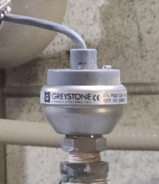
Some pressure switches are capable of directly switching on and off the electric motor. Other pressure switches can only switch on and off a small control signal. The control signal is then fed into the central controller or is used directly to switch on and off large contactors or motor starters.
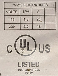
For a direct motor switching the power rating of the pressure switch contacts has to exceed the power rating of the compressor motor (Figure 2), therefore direct motor switching pressure switches are only seen on smaller air compressor, with relatively small motors.
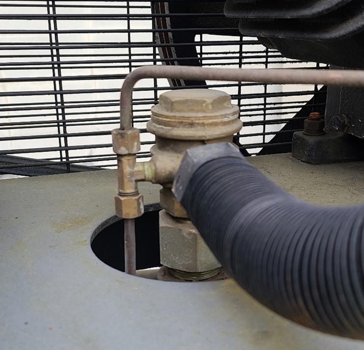
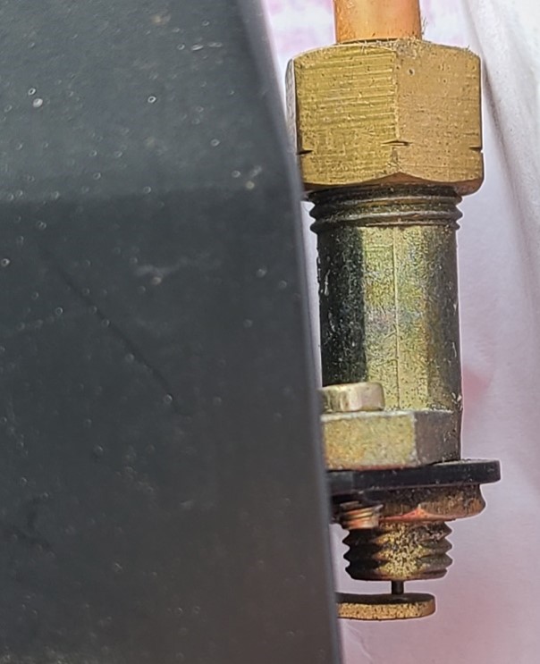
On start/stop reciprocating piston compressors, a blow down valve/unloader valve is used to blow-down air pressure from the compressor discharge line. It will blow off any pressure in the pipe between the compressor and the receiver, this is the ssssssh sound heard, when the compressor stops. By bleeding this discharge line down to atmospheric pressure, when the compressor starts up again, the electric motor doesn’t have to overcome the resistance of the system pressure and can start easily. There will also be a check valve, often located right at the point where the compressor discharge pipe is connected to the storage tank( Figure 3), to ensure the whole tank doesn’t drain.
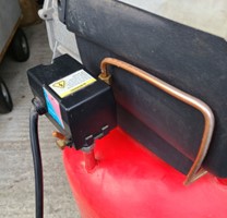
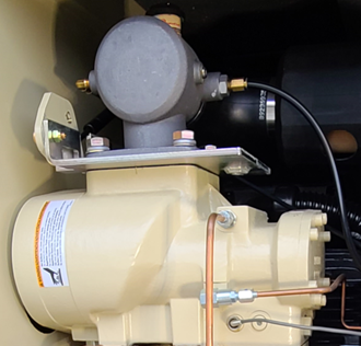
On smaller units, this blowdown valve is often mounted on, or inside the pressure switch (Figure 4). When the pressure switch switches off the compressor, the unloader valve is also actuated by a lever inside the pressure switch.
On newer compressors, a simple solenoid valve is sometimes used to blow down the pressure
Load/Unload
In a load/unload control scheme, a screw compressor remains continuously powered. However, when the demand for compressed air is satisfied or reduced, instead of disconnecting power to the compressor, a device known as an inlet valve is activated (Figure 5). This device proportionately regulates the amount of air that is sucked into the compressor, reducing the capacity of the machine down to typically 25% of the compressor’s capability, thereby unloading the compressor. This reduces the number of start/stop cycles for electric motors over a start/stop control scheme improving equipment service life with a minimal change in operating cost. This scheme is utilised by nearly all industrial air-compressor manufacturers.
When a load/unload control scheme is combined with a timer to stop the compressor after a predetermined period of continuously unloaded operation, it is known as a dual-control or auto-dual scheme. This control scheme still requires storage since there are only two production rates available to match consumption, although significantly less storage than a start/stop scheme.
Modulation
A similar inlet valve as described above continuously modulates capacity to the demand rather than being controlled in steps. This way the compressor can work at any point between 0 and 100%. While this yields a consistent discharge pressure over a wide range of demand, overall power consumption may be higher than with a load/unload scheme, so it is not often used for stationary compressors. But it is often seen in portable diesel engine driven compressors where it is not readily possible to frequently cease and resume operation of the compressor. The continuously variable production rate also eliminates the need for significant storage if the load never exceeds the compressor capacity.
Variable Displacement
Variable displacement alters the percentage of the screw compressor rotors working to compress air by allowing air flow to bypass portions of the screws. While this does reduce power consumption when compared to a modulation control scheme, a load/unload system can be more effective with large amounts of storage (10 gallons per CFM). If a large amount of storage is not practical, a variable-displacement system can be very effective, especially at greater than 70% of full load.
Variable Speed
This type of compressor uses a special drive to control the speed (RPM) of the unit, which in turn saves energy. The benefits of this technology included reducing power cost, reducing power surges (from starting AC motors), and delivering a more constant pressure. The compressor will still have to enter start/stop mode for very low demand as efficiency still drops off rapidly at low production rates.
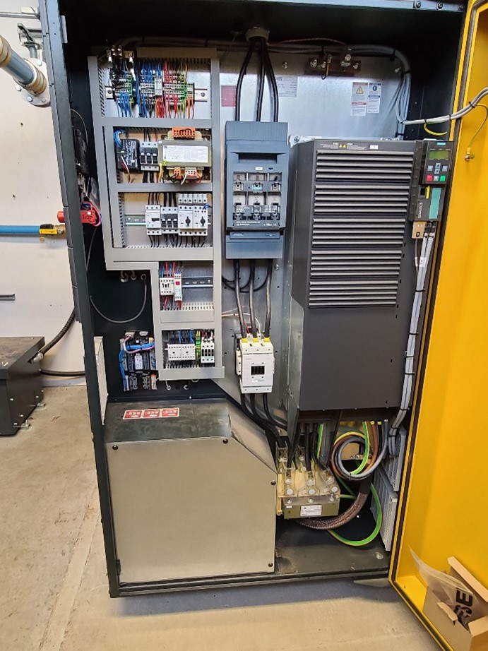
In harsh environments (hot, humid or dusty) the electronics of variable-speed drives will have to be protected to retain expected service life. Therefore the electronic controls will typically be housed in a separate sealed chamber/cabinet of the compressor packaged unit (Figure 6).
Pressure Settings
Many plant air compressors operate with a full-load discharge pressure of 100 psig (700 kPa) and a no-load discharge pressure of 110 psig (770 kPa) or higher. Many types of machinery and tools can operate efficiently with an air supply at the point-of-use of 80 psig (560 kPa) or lower. If the air compressor discharge pressure can be reduced, significant savings can be achieved.
Reducing system pressure also can have a cascading effect in improving overall system performance, reducing leakage rates and helping with capacity and other problems. Reduced pressure also reduces stress on components and operating equipment. However, a reduced system operating pressure may require modifications to other components, including pressure regulators, filters and the size and location of compressed air storage.
Lowering average system pressure requires caution because large changes in demand can cause the pressure at points-of-use to fall below minimum requirements, which can cause equipment to function improperly. These problems can be avoided by carefully matching system components, controls and compressed air storage capacity and location. Any change to the pressure setting of an electronically controlled package unit are typically done by the manufacturers technician as the control will typically require a passcode or connection to separate computer. For smaller systems operated by a mechanical pressure switch pressure setting adjustments can be made if the system is not running at the designed pressure.
Pressure Switch Adjustments
There are two common types of pressure switches. One can adjust only the pressure setting, with a fixed differential, the other can adjust both the pressure setting and the differential. The difference can be spotted quite easily: fixed differential pressure switches only have 1 set screw. Pressure switches with an adjustable differential have a smaller second set-screw.
Pressures setting are increased by adjusting the set screws in (clockwise). For a fixed differential switch turning the single adjustment screw will change both the cut-in and cut out pressure equally. For an adjustable differential switch the small screw will change the maximum pressure (cut-out) only Therefore if both the cut –in and the differential need to be adjusted you should set the cut-in pressure first using the large screw then set the cut-out using the small screw.
Initial Start Checks
As was previously mentioned the initial system start up will often involve the equipment supplier technician, the project engineer, and the installer. Every compressor package is given a test run in the factory and checked before shipment. The test run confirms that the compressor package conforms to the specification data. However, independent of the checks made at the factory, the compressor package could be damaged during transport. For this reason, we recommend that the compressor package is examined for such possible damage. Observe the compressor package carefully during the first hours of operation for any possible malfunction.
Important functional components in the compressor package (such as minimum pressure/check valve, pressure relief valve, inlet valve and combination valve) are adjusted and fitted to precise setting up regulations. Alterations to these components are not allowed without previous consultation with the manufacturer.
The following represent a typical start-up checklist for a compressed air system:
- Do not operate the compressor package in spaces where heavy dust conditions, toxic or flammable gasses could exist
- Do not connect the compressor package to a supply voltage other than that stated on the nameplate.
- Do not install the compressor package in a space subject to freezing temperatures.
- If exhaust air ducts are to be installed they must be at least the cross-section of the cooling air outlet of the compressor package
- Ensure the air intake is clear and installed the required minimum distance from a wall
- Check the oil level in the oil separator tank
- For initial start of a screw compressor add the prescribed quantity of oil to the filler plug on the air inlet valve
- Bump the motor to check rotation direction
- Check the tension of the V-belts
- Check the door interlock safety switch
- Check or oil leaks
- Check the air pressure set points
- Test emergency stop pushbutton
Now complete Self-Test 1 and check your answers.
Self-Test 1
Self-Test 1
- Which leak detection method is considered the compressed air industry standard?
- Listen and feel
- Ultrasonic testing
- Soapy water
- When testing for leaks in a compressed air system, where are the leaks frequently found?
- At the compressor
- At the point of use
- The entire piping network
- The last 9 m (30 ft.) of piping before the point of use
- In a poorly maintained industrial compressed air system, what percentage of a compressor’s output could be lost from air leaks?
- 10–20%
- 20–30%
- 30–40%
- 40–50%
- What advantages are there to reducing the system air pressure to a full-load setting just above the maximum system requirement?
- Cost savings
- Improved system performance
- Reduced leakage rates
- Reduced stress on system components
- All of the above
- What problem could occur when reducing the system air pressure to a full-load setting just below the minimum system requirement?
- Equipment malfunction
- High air velocities
- Excessive compressor vibration
- Excessive condensation formation
- Which of the air quality parameters listed below is not measured?
- Solid particle content
- Water vapour content
- Oil vapour content
- Discharge temperature
Check your answers using the Self-Test Answer Keys in Appendix 1.
Media Attributions
- Figure 1a Pressure sensor by Rod Lidstone, Camosun College is licensed under a CC BY 4.0 licence.
- Figure 1 b Pressure switch by Rod Lidstone, Camosun College is licensed under a CC BY 4.0 licence.
- Figure 2 Pressure switch electrical contact ratings by Rod Lidstone, Camosun College is licensed under a CC BY 4.0 licence.
- Figure 3 Angle check valve with pressure switch/unloading line connection by Rod Lidstone, Camosun College is licensed under a CC BY 4.0 licence.
- Figure 4 Pressure switch activated, blow down valve by Rod Lidstone, Camosun College is licensed under a CC BY 4.0 licence.
- Figure 5 Screw Compressor with inlet/unload valve by Rod Lidstone, Camosun College is licensed under a CC BY 4.0 licence.
- Figure 6 Compressor self contained electronic controls chamber by Rod Lidstone, Camosun College is licensed under a CC BY 4.0 licence.
