Learning Task 2
Install Compressed Air Systems
Installing a quality compressed system requires that attention is paid to many design details such as proper equipment selection and piping layout as well as the installation instructions and or specifications.
Codes and Regulations Regarding Pressure Vessels
A compressed air system receiver is probably the most common type of unfired pressure vessel used by industry. Due to minimum size inspection thresholds employed by the vast majority of jurisdictions, many of the smaller air receivers do not qualify for a mandatory in-service inspection, but they do require a label certifying they are manufactured to a minimum standard. Larger installations fall under the requirements of the Boiler and Pressure Vessel Program administered by the Technical Safety BC.
The Boiler and Pressure Vessel Program is a safety program that regulates the safe design, manufacture, operation, maintenance, repair, inspection and alteration of pressure equipment in British Columbia. Generally, the program oversees pressure equipment by enforcing the Safety Standards Act and the Power Engineers, Boilers, Pressure Vessel and Refrigeration Safety Regulation.
Compressed Air Hazards
Compressed air systems pose risks to workers in the form of high-velocity air and excessive noise. In many Canadian jurisdictions, cleaning with compressed air is not allowed by law. Although many people know using compressed air to clean debris or clothes can be hazardous, it is still used because of old habits and the easy availability of compressed air in many workplaces.
However, cleaning objects, machinery, bench tops, clothing and other things with compressed air is dangerous. Injuries can be caused by the air jet and by combustible dust re-entering the air.
There are certain regulations in BC that deal with these two risk areas.
WorkSafeBC Regulation 4.42 (4) “Cleaning with compressed air” states that:
Compressed air may be used in specially designated areas for blowing dusts or other substances from clothing being worn by workers, provided that
- the substances have an exposure limit greater than 1.0 mg/m3, as established by Section 5.48,
- appropriate respirators and eye protection are worn, and
- the compressed air supply pressure is limited to a pressure of 70 kPa gauge (10 psig), or safety nozzles which have the same pressure limiting effect are used.
Large reciprocating air compressors that produce high noise levels at low frequencies can be found in a wide range of manufacturing plants, and this can be hazardous to workers in the area.
WorkSafe BC Guideline G7.6-(2) “Implementing Controls” requires that:
the employer, when practicable, to implement one or more options for engineered noise control to reduce worker exposure to or below the exposure limits. An example of an engineered noise control strategy for a compressed air system would be to install compressed air exhaust mufflers, air jet noise silencer nozzles, etc.
System Design
The purpose of compressed air piping systems is simple: to deliver compressed air to where it is needed. However, designing a compressed air system is more difficult one might imagine — the compressed air has to be delivered with sufficient volume, good enough quality and enough pressure to power the components that require compressed air. When designing an air distribution system layout, it is best to place the air compressor and its related accessories where temperature inside the plant is the lowest (but not below freezing). A projection of future demands and tie-ins to the existing distribution system should also be considered.
If the compressed air piping design is not well done, the energy costs will go up, equipment may fail, production efficiencies may be reduced and more maintenance may be required.
Pipe Sizing
Owners of compressed air systems tend to focus on the compressor and think of the piping as less of a concern. However, just as hearts can fail due to clogged arteries, compressors can fail due to under sized piping.
Pressure drop is a term used to characterize the reduction in air pressure from the compressor discharge to the actual point-of-use. Pressure drop occurs as the compressed air travels through the treatment and distribution system. A properly sized piping system should have a pressure loss of much less than 10 percent of the compressor’s discharge pressure, measured from the receiver tank output to the point-of-use.
System Installation
In addition to the considerations of appropriate sizing of equipment and layout, it is necessary follow all manufacturers specifications and installation instructions to ensure proper air supply, good tool performance, and optimal production.
Compressor Installation
Oversized air compressors are extremely inefficient because most compressors use more energy per unit volume of air produced when operating at part-load. In many cases, it makes sense to use multiple, smaller compressors with sequencing controls to allow for efficient operation at times when demand is less than peak.
Proper installation of the air compressor is essential for safe and trouble-free operation. Air compressors are easy to install, provided the installation is done in accordance with the manufacturer’s recommendations and with all applicable AHJ requirements.
The compressor unit must be located in a dry, clean, cool and well-ventilated area. If possible, the compressor should be located in a separate room or area, away from the general operations of the facility. A compressor unit releases a great deal of heat that could cause severe problems. It is very important that the unit be located in a relatively large area or, when in an enclosed area, cool air is introduced and the heat is removed by means of intake and exhaust fans. The amount of heat generated by an air compressor is calculated by simply multiplying the unit’s horsepower by 2500 BTU/hr. Many systems will recover this energy for space or water heating. Water cooled compressors are excellent for heat recovery applications.
Ensure that the floor under the unit is smooth and level. The compressor must sit squarely on its base. If anchoring a compressor base to the floor, make sure that a vibration isolation system is used. Do not bolt down tightly.
Allow room for easy access to the unit for maintenance purposes. Should it be necessary to service the unit, ensure the power source has been shut down and locked out. This must be done to prevent personal injury or damage to the unit.
The compressor must be correctly connected to the building’s electrical services. Any electrical work must be carried out by a qualified electrician and be done in such a way that it meets all applicable codes and regulations.
Summary of installation recommendations
Following are some common installation recommendations:
- Smaller rotary and tank-mounted reciprocating compressors require a floor capable of supporting the static weight of the compressor package.
- Larger reciprocating compressors may require a concrete foundation or structural steel support designed to stabilize forces that are present during normal operation.
- Locate the compressor in an area where the added noise will not interfere or violate the WorkSafeBC Regulation.
- All compressors produce heat during the compression process. This heat must be removed from the compressor room for proper operation of the compressor. It is very important to provide sufficient ventilation for all equipment that may be installed in the compressor room. All compressor manufacturers publish the range of allowable operating temperatures.
- Properly vent the exhaust from engine-driven compressors. Be sure that the exhaust cannot be redrawn into the plant through HVAC systems or drawn into the air inlet of compressors.
- Leave sufficient space around the compressor to permit routine maintenance. It is also suggested to provide space for the removal of major components during compressor overhauls.
- Select piping systems that have low pressure drop and provide corrosion-free operation. When selecting the main air headers, size for a maximum pressure drop of 1 to 2 psig (7 to 14 kPa). It is good to oversize the header, as the one size higher will not add much to the cost but will provide additional air storage capacity and allow for future expansion.
- Maximize energy efficiency by minimizing pipe runs and associated pressure drops. A closed-loop distribution header has the advantage of allowing more than one path for air flow and reduces pressure drop.
- Ample compressed air storage in air receivers is desirable close to the compressor to prevent frequent loading and unloading. Secondary storage, close to points of intermittent but substantial demand, prevents sudden pressure drops in the system and allows recovery time before the next demand cycle.
- Provide a means to drain moisture that may accumulate in piping. Headers should be pitched to enhance drainage and drip legs installed in all low points.
- Connect all drain valve outlets to an approved drain. Be sure the drain is vented. Do not pipe drain valves into a common closed pipe or header upstream of the approved drain.
- Condensed moisture may contain compressor lubricants and other chemicals that must be disposed of in accordance with all AHJ regulations.
- If equipment, piping or drains are exposed to freezing temperatures, be sure to insulate and heat trace to prevent freezing.
Vibration isolation
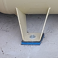
Air compressors are a major source of vibration. If this vibration is transferred to the structure, it can create serious noise problems in many different areas. Vibration can travel through the structure as well as through the connecting piping. Isolation mounts reduce the transmission of the vibration, but care must be taken when selecting these devices, as an improper mount for an application can actually make the problem worse.
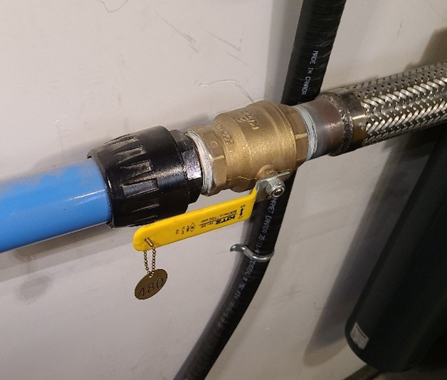
For proper installation, vibration pads should be placed between the baseplate (or tank feet supports) and a level floor. A high temperature–rated steel-braided, vibration isolation flex hose should be used to connect the compressor to the air distribution line (Figure 1 and 2). A rigid connection will not allow any movement between two components.
Piping Installation
The length of the network should be kept to a minimum to reduce pressure drop. Air distribution piping should be large enough in diameter to minimize pressure drop.
Distribution piping design
For reliable and trouble-free air distribution, it is important to correctly size the lines and consider; the piping material, flow resistance, maintenance, future expansion and pipe layout.
When installing any compressed air piping arrangement, keep in mind the following design recommendations:
- Always use full port valves that do not reduce pipe diameter. Ball valves are preferred, but butterfly valves can be used if the piping mains are large enough to warrant their use.
- Discharge piping should be at least the same diameter as the compressor discharge outlet.
- A flexible connection between the rigid air piping and compressor discharge outlet is recommend.
- Install isolation valves at many locations in the air mains. This allows small sections of the main to be shut down to accommodate expansions, additional drops or pipe modifications without shutting down the entire air system. This reduces the temptation to split undersized air drops to many machines whenever an additional drop is required.
- Install an additional tee and fitting to allow temporary connection of mobile or backup compressor for uninterrupted air flow during maintenance/repair service.
- Connect pipe drops off of the top of the air main. This reduces contamination of tools and machinery in the event of an air treatment equipment (dryer and filter) failure, as the contamination will remain at the bottom of the pipe.
- Install periodic drip legs from the bottom of the air mains. These should be used only for draining contaminants and/or checking air quality.
- Mount liquid separator, particulate and oil coalescing filters so the the inlet and outlet connections are horizontal and the filter bowls are vertical.
- If the system is being installed new and is not of an easily modified material, consider placing a tee and valve at each pipe coupling to limit the distance between outlets to 6 m (20 ft.).
Types of piping
Compressed air piping materials can be divided into two basic types: metal (black iron, galvanized iron, stainless steel, copper, aluminum, etc.) and plastic. When design as piping system there are many material selection considerations such as; materials cost, ease of installation, corrosion resistance, flow restriction, pressure rating, durability against external damage. Regardless of the type of piping materials used, it must be rated for at least the maximum working pressure and meet all applicable codes.
Black iron or steel pipe: Compared to copper and aluminum, it is much heavier, more durable, and harder to work with, but less expensive. In sizes 2″ NPS and smaller this pipe is usually threaded; larger diameters are welded. The main limitation with this material is the possibility of corrosion when exposed to condensate (H2O), which would create a problematic source of system contamination.
Galvanized steel piping: This material has the advantage of resisting corrosion better than standard iron pipe. However, over time when corrosion does set in, the galvanizing material peels off. This property is especially harmful on the supply side of the system, as it is now a producer of potentially very damaging solid contaminants between the intake filter and the compressor.
Stainless steel: Stainless steel pipe is often lighter than black iron pipe that has the same pressure and temperature ratings. It is generally a good selection when corrosion is an issue due to high acidity levels in the condensate. Ring gaskets such as those used in groove-and-shoulder type connections are better suited for this material than threaded connections, which often tend to leak.
Copper tube: When selected and connected correctly it is very rugged. Many piping handbooks list the working pressure of copper tubing as 250 psi (1750 kPa) for Type M hard, Type L hard and Type K soft, and 400 psi (2800 kPa) for Type K hard. Due to the potentially high internal pressures and vibration potential, 95-5 soldered or brazed joints are recommended.
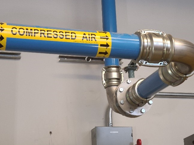
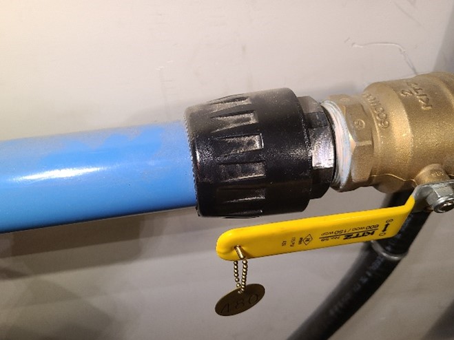
Aluminum: This material has become very popular because its smooth inner surface reduces pressure loss due to friction, and manufactures offer custom fittings and support systems (Figure 1 and 2).
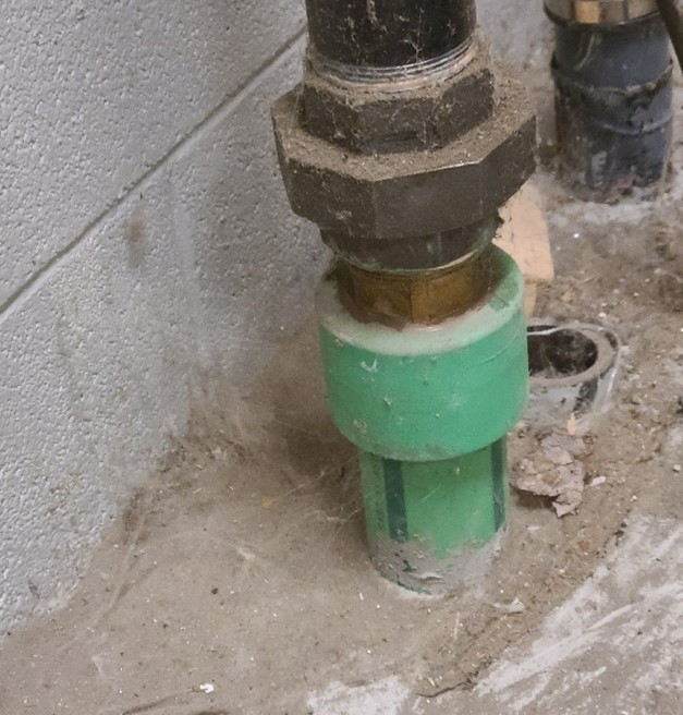
Plastic pipe: This has been used as compressed air piping for many years because the labour costs are less than most metals so the total installation may often be less expensive. However plastic pipes do not have the strength and durability of metal piping systems. PVC and CPVC should never be used for compressed air due to the fact that if it breaks it can shatter and fling sharp fragments of hard plastic through the air. ABS, PP, PE and HDPE plastics are appropriate for use in compressed air piping systems (Figure 3). Typically the mention of ABS makes people think of drainage pipe and fittings but manufacturers produce a specially engineered formulation of ABS that is designed specifically for compressed air systems.
Joining methods
Maintaining the efficiency of a compressed air system is a constant battle, with leaks being a large part of the problem. Pipe joints and fittings are two of the most common areas where leakage occurs in a compressed air system. The type of joining method used usually depends on the system pressure and the material used. In applications using copper, soldering or brazing is standard for small-diameter tubing, while roll grooved joints can be found in larger diameter applications. Plastic compression-type fittings, solvent welding and heat fusion are typically proprietary to the manufacturer.
Many plants now prefer thin wall aluminum tubing due to its lightweight and ease of installation (Figure 4a and 4b). Smaller sizes are often simple push to connect fittings whereas larger diameters may be pressed or grooved. As there are an assortment of connection methods used by different manufacturers it is imperative that you make sure to follow manufacturers assembly instructions for the type of fitting being used.
Connection of Equipment to Piping
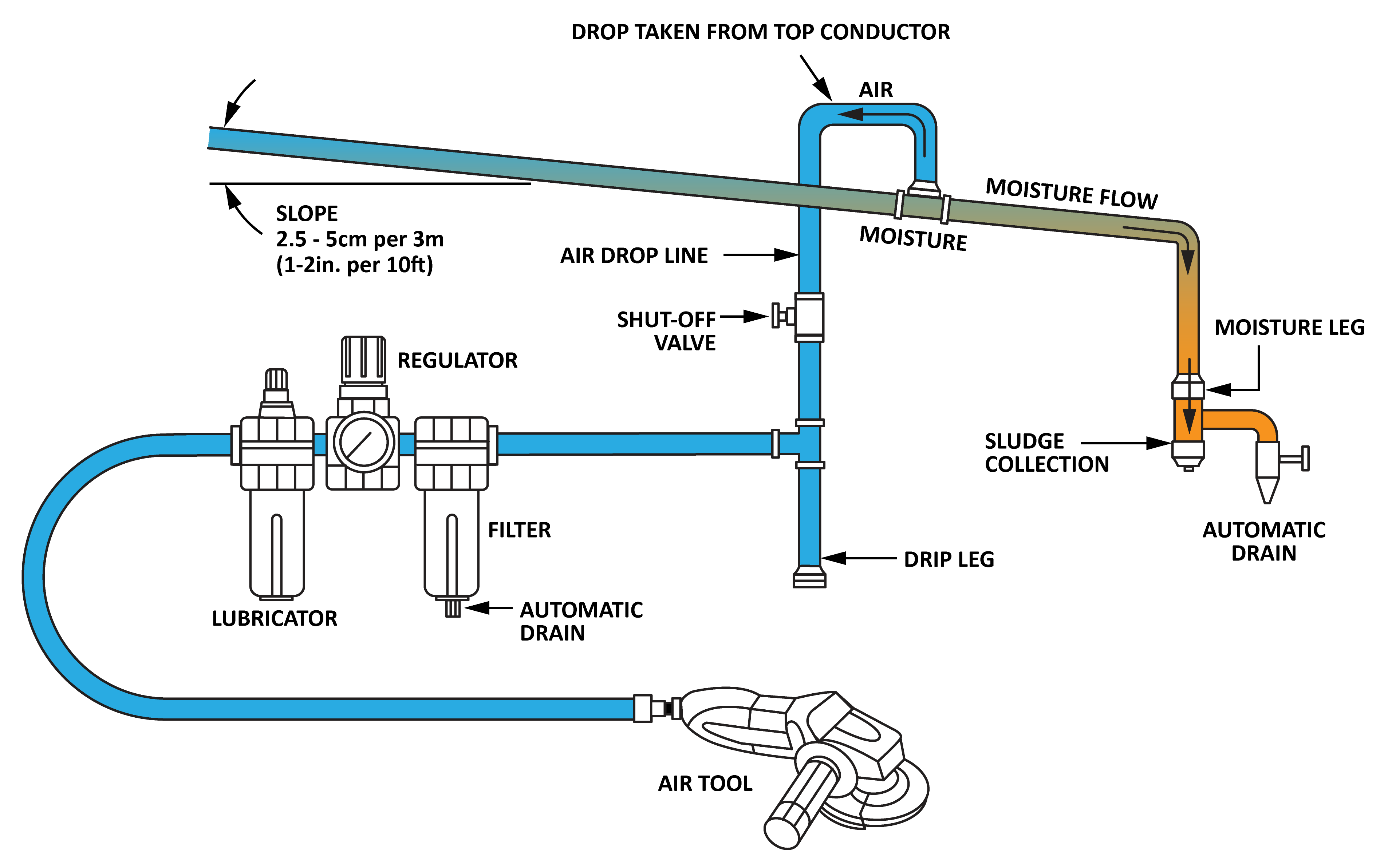
Figure 5 shows a typical drop for an air line and the parts required for the system to work properly. Note that a line sloping toward a water leg alleviates the moisture problem and the drop is taken off the top of the main line. After compression and before use, it is often necessary to condition the air and rid it of contaminants, adjust system pressure to match the end use, and either add or remove oil. It is common to use a single unit, an FRL (filter, regulator and lubricator), for this.
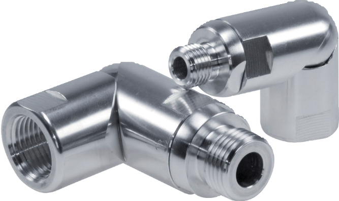
Flexible hose is often used between drop points in the distribution system and air tools as well as between valves and actuators where some sort of pivot mount (Figure 6) is used to mount the actuator.
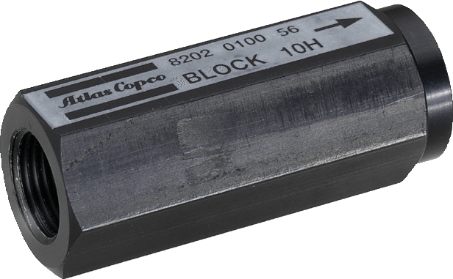
Hoses used to power pneumatic tools should be fitted with a velocity fuse. A velocity fuse (Figure 7) is a valve that closes when excessive flow begins to pass through it. This prevents an air hose from whipping if it is severed, ruptured or otherwise fails.
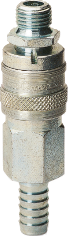
Pneumatic equipment is typically attached to the hose system with quick disconnect couplings (Figure 8). Quick disconnect couplers are the fastest, easiest and most reliable means of joining tools to the distribution system. Usually, quick disconnects are selected based on the size of the supply line pipe threads. However, many quick disconnects are not full-port-designed. Often the female half of a quick disconnect coupling uses a spring-loaded ball-against-seat design to prevent compressed air from escaping to atmosphere when disengaged.
Quick disconnect couplings will cause a pressure loss created by force used to lift the ball and spring off its seat. As well as the fact that the internal orifice size of a ½” quick disconnect might be only ¼” or less.
The importance of the size and type of hose used to connect equipment is often overlooked. Although a small-diameter hose is cheaper, a larger diameter hose will improve system performance. Also, minimize the length of the air hose from the FRL connection point to the equipment location to reduce the pressure drop in the line.
Now complete Self-Test 2 and check your answers.
Self-Test 2
Self-Test 2
- When selecting the size of the supply header in a closed-loop piping configuration, what is the maximum pressure drop that should be allowed in the header?
- 2 psi (14 kpa)
- 5 psi (35 kPa)
- 7 psi (50 kPa)
- 10 psi (70 kPa)
- Approximately how much heat energy would be generated by a 20 hp air compressor?
- 20 000 BTU/hr.
- 30 000 BTU/hr.
- 40 000 BTU/hr.
- 50 000 BTU/hr.
- The WorkSafeBC Regulation allows for blowing dusts or other substances from clothing being worn by workers in specially designated areas. What type of PPE must be worn by the workers?
- Safety glasses and face shield
- Air respirators
- Eye protection and air respirators
- Dust masks and earplugs
- Referring to the previous question, what is the maximum supply pressure of the compressed air allowed by the Regulation?
- 7 kPa gauge (1 psig)
- 35 kPa gauge (5 psig)
- 70 kPa gauge (10 psig)
- 105 kPa gauge (15 psig)
- Moisture drains that are subject to freezing should be protected by either of what two methods?
- Insulation and heat tracing
- Glycol bath and heat tracing
- Insulation and radiant heaters
- Burst plugs and electrical air heaters
- What device should be installed when connecting a compressor to a rigid distribution piping system?
- Spring isolators
- Roller hangers
- High temperature–rated steel-braided, vibration isolation flex hose
- Rigid compressor mounts to eliminate compressor vibration
- What device is installed in a pneumatic hose to prevent flow when the air velocity becomes excessive due to hose failure?
- Excess flow valve
- Velocity harness
- Emergency quick disconnect coupling
- Velocity fuse
- What type of device is used to provide ease of use when connecting pneumatic tools to a compressed air hose?
- A threaded union fitting
- A quick disconnect coupling
- A ring seal coupling
- An air seal coupling
- Where should the branch take-offs be connected when piping the main air discharge header from the receiver?
- Off the top of the main
- Off the bottom of the main
- Off the side of the main
- It doesn’t matter where they are connected.
- Automatic drain traps should be installed in which of the following locations?
- At the bottom of the air receiver
- At the bottoms of drip legs
- At low points in the system
- All of the above
- What is the main limitation in using black iron pipe as a compressed air piping material?
- Possibility of corrosion when exposed to condensate
- The initial cost of the material
- The special hangers required due to the weight of the material
- Leak-susceptible threaded fittings are required on small-diameter piping
- What is the main limitation in using PVC or CPVC as a compressed air piping material?
- Possibility of corrosion when exposed to condensate
- The initial cost of the material
- Possibility the material may shatter when pressurized
- The pressure drop associated with this type of material
- What is the recommended joining method when using copper as a compressed air piping material?
- 50/50 solder
- Threaded joints
- Flare fittings
- 95-5 soldered or brazed connections
Check your answers using the Self-Test Answer Keys in Appendix 1.
Media Attributions
- Figure 1 Vibration pad by Rod Lidstone, Camosun College is licensed under a CC BY 4.0 licence.
- Figure 2 Flex hose by Rod Lidstone, Camosun College is licensed under a CC BY 4.0 licence.
- Figure 3 Polypropylene (PP) underground compressed air line by Rod Lidstone, Camosun College is licensed under a CC BY 4.0 licence.
- Figure 4a and 4b Aluminum compressed air fittings by Rod Lidstone, Camosun College is licensed under a CC BY 4.0 licence.
- Figure 5 Air line drop components by Camosun College is licensed under a CC BY 4.0 licence.
- Figure 6 Compressed air pivot connector by ITA is licensed under a CC BY-NC-SA licence.
- Figure 7 Air hose velocity fuse by ITA is licensed under a CC BY-NC-SA licence.
- Figure 8 Quick disconnect coupler by ITA is licensed under a CC BY-NC-SA licence.
