Learning Task 1
Maintain and Repair Compressed Air Systems
Industrial compressed air systems require periodic maintenance to operate at peak efficiency and minimize unscheduled downtime. Inadequate maintenance can have a significant impact on energy consumption due to lower compression efficiency, air leakage or pressure variability. It can also lead to high operating temperatures, poor moisture control and excessive contamination. Most problems are minor and can be corrected by simple adjustments, cleaning, replacing parts or eliminating adverse conditions.
Manufacturers’ Instructions
All equipment in the compressed air system should be maintained in accordance with manufacturers’ specifications. Manufacturers provide inspection, maintenance and service schedules that should be followed strictly. In many cases, it makes sense from efficiency and economic standpoints to maintain equipment more frequently than at the intervals recommended by manufacturers, which are primarily designed to protect equipment.
Operators should review the equipment information and keep it handy for future reference.
Observe all cautionary references before carrying out any maintenance. Equipment must be locked out before carrying out any repairs and pipework under pressure should be vented or shut off if not stated otherwise in the service manual.
Areas requiring periodic maintenance
Conducting routine preventive maintenance on a schedule is a useful way to perform necessary inspections and maintenance in a way that will minimize disruption to plant operations.
Taking a few minutes to check the following areas and there components should be part of a regular maintenance routine.
- Compressor package
- Air filters
- V-belts
- Electrical connections
- Oil level
- Oil filter
- Oil separator
- Operating temperature
- Cooling system
- Pressure relief valve
- Compressor drive
- External after coolers
- External oil and water separators
- Air Dryers
- Drain traps
- System leaks
- FLR’s
Maintenance contracts have become a popular method for compressor users to plan and budget for equipment maintenance.
Compressor Package Maintenance
The main areas of the compressor package in need of maintenance are the compressor, heat exchanger surfaces, air lubricant separator, lubricant, lubricant filter and air inlet filter.
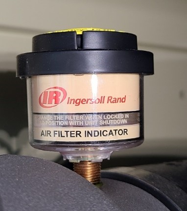
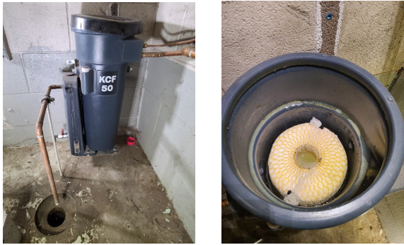
Inspect and clean or replace air inlet filters. A dirty filter can reduce compressor capacity and efficiency. Filters and inlet ducting should be maintained at least per manufacturer’s specifications, taking into account the level of contaminants in the facility’s air. Some air filters cartridge housings may have a maintenance indicator (Figure 1)or gauge which measures the flow restriction created by a dirty filter.
If the compressor is belt driven, check for wear and that the belts are correctly tensioned as per the manufacturer’s recommendation. If they are slack, energy loss will occur due to belt slippage. If they are too tight, the belts will be subject to excessive stress and the compressor and motor bearings will be placed under extra load.
The compressor and intercooling surfaces need to be kept clean and foul-free. If they are dirty, compressor efficiency will be adversely affected. Fans and water pumps should also be inspected to ensure that they are operating at peak performance.
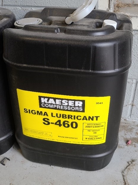
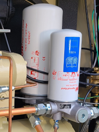
Inspect the compressor lubricant level daily and top off as needed with the manufacturers approved product. The compressor lubricant and lubricant filter need to be changed as per manufacturer’s specifications (Figure 2). Lubricant can become corrosive and harm the equipment, reducing system efficiency. For lubricated-injected rotary compressors, the lubricant lubricates bearings, gears and intermeshing rotor surfaces, acts as a seal and removes most of the heat of compression.
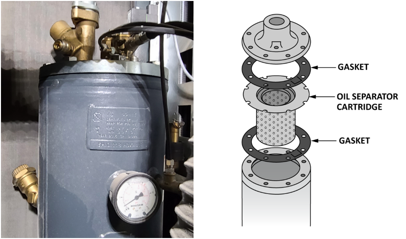
Lubricated rotary screw compressors will also have an oil separator (Figure 3) which recovers lubricant from the compressed air discharge, and returns it to the compressor injection chamber. The service life of the oil separator filter cartridge is influenced by the degree of contamination of inlet air, it is recommend that the oil separator cartridge is changed at the same time as the oil. The compressor package will need to be depressurized so that the air lines will need to be disconnected. Once the cover plate is removed the old gaskets and separator cartridge can be replaced.
Grease and clean electric motors. Poor maintenance will waste energy and may cause failure before the end of its expected lifetime. Check the manufacturers instructions as many motors now have greaseless bearings.
Check the operating temperature of the compressor. Air compressors are often subject to temperature extremes, especially if they are installed outdoors or in a warehouse without temperature controls. Large swings in temperature can lead to air compressor overheating in the summer or freezing in the winter. Operating at the optimal operating temperature range will and extend the life of the compressor. The ideal operating temperature for an air compressor is between 50 and 85-degrees Fahrenheit. Within this range, mechanical components are not at risk of freezing or overheating due to ambient conditions.
If the ambient temperature in the area where the air compressor is located cannot be kept above 40°F, you may be able to install trace heating around pipes, an internal heater for your air compressor, and insulation to maintain safe operating temperatures inside the air compressor.
The compressor temperature may be high due either external or internal conditions.
External environmental conditions that lead to air compressor overheating include:
- High ambient temperatures
- Inadequate ventilation around the compressor
- Positioning the compressor next to heat-generating equipment
Some of the most common internal causes of air compressor overheating include:
- Dirty or blocked oil filter
- Blockage of oil cooler
- Failed fan
- Low sump oil level
- Thermal valve failure
For water-cooled systems, check the quality of water, especially pH and TDS (total dissolved solids), flow and temperature differential. Regularly clean and replace filters.
Condensate Draining
Condensate drains are possibly the least glamorous and most ignored component of a compressed air system. Nevertheless, there are very few things that can cause more trouble than the condensation that accumulates in the system.
Condensate drains can be found in numerous locations in a system, including:
- intercooler
- aftercooler
- filter
- dryer
- receiver
- drip leg
- point of use
There are many types of drains, and all have specific issues that demand attention. The following are the main types of drains and some of their shortcomings. These issues should be addressed as part of the maintenance/inspection routine.
Manual drains
These are opened manually to remove the accumulated condensation. Certain considerations should be noted when using these drains:
- Avoid leaving manual valves partly open to constantly drain the condensation. This is tempting on drain points that have a high volume of condensation, such as the aftercooler, separator and the air receiver tank.
- Leaving the valve open will eliminate the need for continued attention, and it will effectively remove condensation from the system. However, this creates an obvious compressed air leak and, depending on the size of the system, might actually incur the waste of thousands of dollars on energy.
- Map out the drain locations on your entire system to avoid forgetting about manual drains on remote or low-volume drain points. This might include inline filter drains that are located high in the air piping and drip lines on the outer reaches of the pipe distribution system.
- Create a maintenance schedule for draining based on system use/demand.
Internal float drains
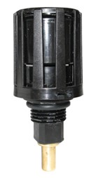
Internal float drains use a float mechanism in a housing to control the valve that dumps the condensation (Figure 4).
- Remember to clean the housing and the float mechanism regularly.
- The moving parts of this drain are always in contact with the condensation. This liquid becomes contaminated by dirt, rust, pipe scale and oil from the carryover on lubricated compressors. This mixture will cause the float mechanism to malfunction.
- The float will jam in either the open or closed position. You will be able to hear the air leak if the float becomes stuck in the open position. However, if the float sticks in the closed position, you may not realize that there is a problem until liquids begin to back up into the system.
Pneumatic/mechanical drains
For pneumatically operated drains (Figure 5) ensure that the pilot air supply is installed correctly to the actuating cylinder. The float mechanism is always in contact with the condensation, so it must be cleaned regularly.
Series timed electric drains
These use an electronic timer that activates a valve to dump the condensation (Figure 6).
- You can adjust the drain cycles by setting the number of cycles per hour and the length of time the valve will stay open during each cycle. The theory is to set the timer for a long enough period to completely drain the condensation without setting it long enough to waste compressed air.
- The problem is that the amount of condensation will vary according to changes in the temperatures and relative humidity of the ambient environment. This means that the settings will have to be adjusted to compensate for climate and seasonal changes.
- Take the time to change the settings on your timer drains to match the changes in the ambient temperature and humidity.
- Avoid the temptation of using settings that will keep the valve open longer than necessary. This approach may get the condensation out of the system, but it sets up an automatic leak point for compressed air.
Electronic demand drains
Electronic demand drains have electronic sensors that monitor the level of condensation within a reservoir (Figure 7). One sensor opens the outlet valve to dump the condensation when the housing registers as being full. Another sensor closes the outlet valve before completely draining the condensate to avoid wasting air.
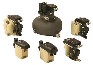
Maintaining electronic demand drains:
- Clean the sensors and the housing of an electronic drain regularly.
- The sensing devices are in constant contact with the contaminants found in compressor condensation. This will foul the sensors and reduce the reliability of the drain.
Oil/Water Separators
The condensate that is drained from the system is not just water, but usually contains oil and solid particles. This oil/water mixture is classified as hazardous waste and cannot be discharged into municipal wastewater systems unless the oil and contaminants are removed. A condensate management system will pipe all of the drains to an oil/water separator (Figure 8) before draining to the sewer. The separated oil is captured in an adsorption filter which will need to be monitored, replaced, and appropriately disposed of when necessary.
Filters
Filter maintenance and monitoring are crucial to system performance. Any contaminants not trapped in the filter will eventually damage tools and equipment. When selecting filters, ensure that the liquid loading (amount of water or oil) as well as the solid particle size do not exceed the filter rating. Typically, you should start with a bulk filter to remove contaminants at the aftercooler, followed by a fine or extra-fine filter downstream of a refrigerated dryer or upstream of a desiccant dryer.
Filter maintenance recommendations:
- Use the proper micron rating as specified by the OEM.
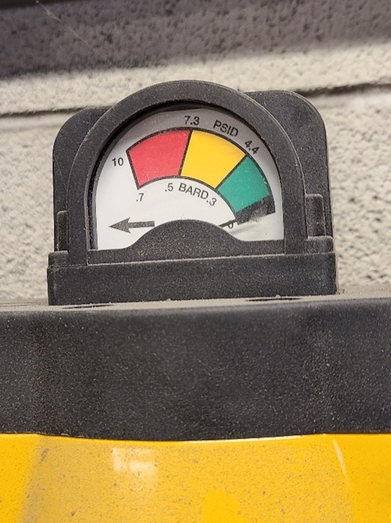
- Check the pressure differential (Figure 9) and, change the filter cartridge when the pressure drop exceeds 8–10 psid (56 to 70 kPad).
- Check for worn/damaged seals.
- Check for structural integrity.
- Replace the filter after it has been cleaned two or three times.
Air Dryer Maintenance
Hot compressed air contains large amounts of water vapour. When travelling downstream, the water vapour condenses into liquid and causes corrosion in piping, components, air tools and production equipment. Compressed-air dryers are an indispensable part of any clean air treatment process and must be maintained to ensure they remove harmful moisture.
Refrigerated dryers
A refrigerated dryer consists of heat exchangers, refrigeration compressor, condenser, separator/ drain and control system. Clogged condensers are the common cause for most dryer problems.
- Periodically clean the fins with compressed air or a bristle brush to ensure enough refrigerant is transformed into a liquid state for proper heat removal in the evaporator.
- Do not bend or damage the fins of the heat exchanger during cleaning.
- Check separator and drain function regularly by monitoring the discharge amount. Even the best drain needs to be serviced or rebuilt at least once a year.
Desiccant dryers
Pre-filtration is essential to protect the desiccant from oil and bulk water.
- Check the pressure drop across the filters and change the filter cartridge when the pressure drop exceeds 8–10 psid (56 to 70 kPad).
- Check drains for proper operation and rebuild them at least once a year.
Desiccant is very sensitive to oil as well as “dusting,” which occurs when desiccant is subjected to excessive air flow through the dryer.
- Sample the desiccant (drain port on bottom of tower) and examine it for proper size (dusting reduces size) and discoloration, which indicates oil contamination.
- Replace the desiccant every two to three years.
Regenerative desiccant dryers use a variety of control valves to operate. These normally include an inlet switching valve, purge exhaust valves, check valves, and solenoid valves.
Purge exhaust mufflers reduce the noise level during depressurization and purging. Over time the mufflers will become clogged with desiccant dust. A higher than normal back pressure on the regenerating desiccant tower is an indication of clogged mufflers. If the off stream tower is showing a few pounds of pressure during regeneration, the muffler could be clogged.
Deliquescent dryers
Check the dryer’s sight window periodically to ensure its filled with manufacturers recommended tablets, and drain the vessel at regular intervals (once per 8-hour shift).
Membrane dryers
These are completely maintenance-free but require reliable pre-filtration. Check requirements for pre-filtration and drain traps and service per instruction manual.
Quick Disconnects
Most manufacturing plants that employ compressed air use quick-disconnect couplings at equipment locations. Proper selection and sizing of these connectors are usually not given the consideration they deserve. Although these inexpensive devices are not a major maintenance expense, poorly chosen couplings can create unexpected problems with productivity, energy conservation and safety.
If pressure drop through the coupling is an issue, a good alternative to the standard quick disconnect is a version with a full-port design. These disconnects are similar to a full-port ball valve. The internal orifice is the same size as the pipe thread size, and there is no ball and spring to introduce pressure drop.
Reducing pressure drops in the coupling and hose assembly allows a system to operate more efficiently at lower pressures. Not only does operating the compressor at a lower pressure save energy, but reduced pressure means less air is wasted through any unregulated leaks, further reducing energy requirements and associated costs.
A maintenance-saving solution is to minimize the effect of vibration or shock from equipment by using a 60-cm (2 ft.) whip hose between the tool and the coupling. Check couplings periodically for leaks in the coupled and uncoupled positions. Compressed air leaks are expensive in terms of energy cost and excessive compressor capacity. Replace couplings that are not performing properly. Although repairable, their initial cost does warrant the cost of labour to repair them.
System Leaks
Leaks can be found throughout the system from the compressor all the way to the points of use. Check lines (joints), fittings, drains, relief valves, clamps, drain valves, hoses, disconnects, regulators, filters, lubricators, gauge connectors and end-use equipment for leaks. A common area to encounter leaks is within the last 9 m (30 ft.) of piping before the point of use. This is generally the location of the smallest piping and hose sizes, which cause high air velocities. This section is also subject to the most vibration and stress from the end user.
Generally, the more fittings and hoses you have in the system, the more leaks you are likely to have. They may occur in poorly installed fittings or in joints that have loosened or degraded over time.
Leak detection methods
Too many users simply accept leaks as an unavoidable aspect of using compressed air—in other words, just a cost of doing business. While it may not be practical to eliminate all leaks, it is not difficult to greatly reduce them. First, you must find them. There are three common methods of leak detection: listening and feeling, the soapy water technique and ultrasonic leak detection.
Listen and feel: A simple way to detect leaks is by listening for and then feeling leaks. This is only effective for large leaks that you can get close enough to feel, and you must be able to hear them above the noise of plant equipment. This technique will not work for most leaks.
 Do not place your bare skin too close to a compressed air leak.
Soapy water: In this method, soapy water is applied with a brush or spray bottle to areas where a leak is suspected. If a leak is present, soap bubbles will form. Although reliable, it is time consuming and requires direct physical access to the entire piping system. Leaks in overhead piping or in hard-to-access areas may not be detected. Further, this method does not provide information on the relative volume of each leak.
Ultrasonic: The industry standard and best practice is to use ultrasonic leak detection. This is the most versatile form of leak detection and can detect leaks as small as a pinhole. Because background noise does not interfere with its results, this method is both fast and accurate and does not require plant downtime to conduct a leak detection audit. Unlike the first two methods, it can be done without physical contact with the leaks. When compressed air is released into the atmosphere, the turbulence creates ultrasonic noise inaudible to the human ear but detectable with the right equipment. Ultrasonic leak detection equipment typically consists of directional microphones, amplifiers and audio filters, and it usually has either visual indicators or earphones to help the auditor identify the leaks.
Air leaks can be a significant contributor to energy wastage in a compressed air system, and in some instances they can lead to productivity losses. It is not unusual at typical industrial facilities to encounter 20 to 30 percent of a compressor’s output being lost in the form of air leaks. Proactive leak management programs (detection and repair) can reduce leaks to less than 10 percent of a plant’s compressed air production.
Now complete Self-Test 1 and check your answers.
Self-Test 1
Self-Test 1
- What are two advantages to servicing compressed air equipment more frequently than recommended by the manufacturer?
- Higher system capacity and plant production gains
- Higher efficiency and economic gains
- Higher system pressures and smaller distribution piping costs
- What two adverse effects are present when the compressor air intake filter is not maintained regularly?
- Reduced capacity and reduced efficiency
- Lower system pressure and larger distribution piping costs
- Higher condensate accumulation and loss of end-user pressure
- What is the most often ignored component of a compressed air system when it comes to proper maintenance?
- The aftercooler heat rejection fins
- The FLR assemblies
- The condensate drains
- The air intake filters
- Which type of condensate drain is most prone to air leakage due to neglect?
- Electronic demand drains
- Manual drains
- Series timed electric drains
- Pneumatic/mechanical drains
- How many cleanings should a filter undergo before it is replaced?
- 1 or 2
- 2 or 3
- 3 or 4
- 5 or 6
- What is the common cause of most refrigerated air dryer problems?
- A clogged condenser
- A clogged separator
- Membrane media clogging
- Waterlogging
- What is the maximum acceptable range of pressure drop across a pre-filter cartridge serving a desiccant air dryer before it must be replaced?
- 1–2 psi (7 – 14 kPa)
- 2–4 psi (14 – 28 kPa)
- 4–6 psi (28 – 42 kPa)
- 8–10 psi (56 – 70 kPa)
- What is the term given to a desiccant material when it is exposed to excessive air flow through a dryer?
- Air binding
- Saturation
- Scrubbing
- Dusting
- What device is installed between the pneumatic tool and a quick-disconnect coupling to minimize the effect of vibration or shock from equipment?
- A quick disconnect
- A spring isolator
- A 30-cm (2 ft.) whip hose
- An isolation union
- If a quick-disconnect coupling is of a full port design, what does this imply?
- The internal orifice is smaller than the pipe size and does have a ball or a spring.
- The internal orifice is the same size as the pipe size and does have a ball or a spring.
- The internal orifice is the same size as the pipe size and does not have a ball or a spring.
- The internal orifice is smaller than the pipe size and does not have a ball or a spring.
- When testing for leaks in a compressed air system, where are the leaks frequently found?
- At the compressor
- At the point of use
- The entire piping network
- The last 9 m (30 ft.) of piping before the point of use
- In a poorly maintained industrial compressed air system, what percentage of a compressor’s output could be lost from air leaks?
- 10–20%
- 20–30%
- 30–40%
- 40–50%
- Which leak detection method is considered the compressed air industry standard?
- Listen and feel
- Ultrasonic testing
- Soapy water
Check your answers using the Self-Test Answer Keys in Appendix 1.
Media Attributions
- Figure 1 Compressor inlet filter gauge by Rod Lidstone, Camosun College is licensed under a CC BY 4.0 licence.
- Figure 2a Manufactures compressor lubricant by Rod Lidstone, Camosun College is licensed under a CC BY 4.0 licence.
- Figure 2b Compressor oil filters by Rod Lidstone, Camosun College is licensed under a CC BY 4.0 licence.
- Figure 3 Oil separator and cartridge components by Rod Lidstone, Camosun College is licensed under a CC BY 4.0 licence.
- Figure 4 Internal float drain by ITA is licensed under a CC BY-NC-SA licence.
- Figure 5 Pneumatic/mechanical drain by ITA is licensed under a CC BY-NC-SA licence.
- Figure 6 Series timed electric drain by ITA is licensed under a CC BY-NC-SA licence.
- Figure 7 Selection of electronic demand drains by ITA is licensed under a CC BY-NC-SA licence.
- Figure 8 Oil/water separator by Rod Lidstone, Camosun College is licensed under a CC BY 4.0 licence.
- Figure 9 Filter differential pressure indicating gauge by Rod Lidstone, Camosun College is licensed under a CC BY 4.0 licence.
