Learning Task 3
Active Solar Space Heating Systems
It is both unrealistic and uneconomical to attempt to supply 100% of a space heating load through an active solar system. This is due to the fact that, when space heating needs are highest, solar availability is lowest. This means that active solar systems are almost always supplemented by an auxiliary heat source, such as forced air or electric baseboard convection. Whatever the auxiliary heat source, carefully planned and constructed systems can effect fully automatic changeover between systems without the occupants noticing that it is happening.
Three principles that need to be observed when using solar for space heating are:
- Space heating distribution systems that operate using low-temperature water will result in greater collector efficiency
- Conventional energy sources (eg. Oil, gas, electric, etc.) should only be operated when “instantaneous” heat is need – they should be left “off” and not producing heat at all until immediately needed
- As typical with the systems covered, all solar equipment must be protected from freezing during periods of inactivity
Active Solar Supplying Hydronic Space Heating Systems
Hydronic-based solar subsystems can supply heat to either forced air or hydronic space heating systems. Ideally, radiant floor systems are the most logical recipients of solar energy. They typically operate using water temperatures of 100 – 130°F (38 – 54°C). If tube spacing, under-slab insulation and floor covering considerations are carefully planned, those water temperatures can be further lowered, thereby increasing the effectiveness of a solar energy supply. Figure 1 below illustrates an antifreeze-based solar subsystems supplying a radiant panel distribution system that is supplied by a gas-fired boiler.
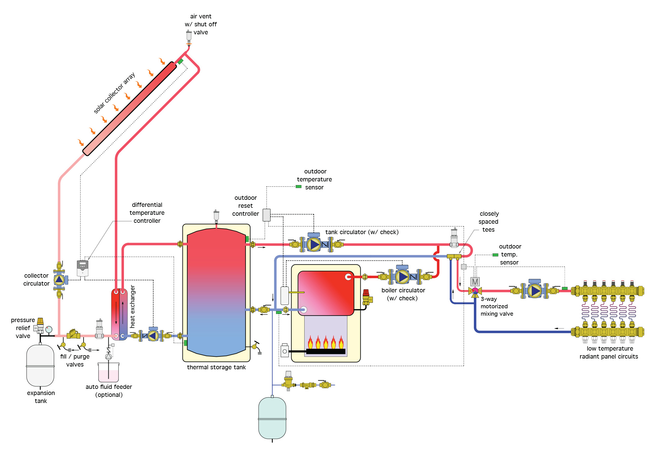
The 100% water in the thermal storage tank and boiler is separated from the antifreeze-protected solar loop by a stainless – steel plate exchanger. All the components of the solar loop are typical of those we’ve previously studied. An optional fluid feeder is shown that constantly monitors the pressure in the solar loop and automatically adds antifreeze mixture whenever the pressure in the solar loop drops below a setpoint for any reason. These are usually only used in large commercial systems.
An outdoor reset controller is used to monitor the temperature at the top of the storage tank and constantly calculate the water temperature required at the distribution piping for the radiant floor panels. On a call for heat, the controller determines if the storage tank temperature is at or above the temperature needed for the distribution system and if it is, the tank circulator turns on while the boiler and boiler circulator remain off. Water passes through the air separator which is mounted on the primary loop and on to the closely-spaced tees. These tees are the interconnection between the primary loop and the 3-way motorized mixing valve in the distribution system. Their spacing ensures that the operation of the primary (supply loop) and secondary (distribution) pumps won’t affect each other’s operation. The motorized 3-way valve automatically adjusts its position to provide water of the proper temperature to the distribution piping by mixing cool return water with supply water that may be hotter than needed. The 3-way valve is also operated by an outdoor reset controller.
On a call for heat, if the tank’s temperature is too low, the boiler and boiler circulator are powered on while the tank circulator remains off. The 3-way motorized mixing valve maintains the required temperature to the distribution system. Properly-placed tees and isolation valves allow the solar system to be shut down while still maintaining the operation of the boiler.
Note that water heated by the boiler does not circulate through the storage tank. This allows residual heat in the tank to slowly transfer from the tank into the surrounding space. The cooler the storage tank, the sooner the solar collection process can begin when sunshine returns. When the storage tank warms back above the minimum usable temperature of the distribution system, the storage tank again becomes the heat source for the system.
Figure 2 below shows a similar system using a drainback feature and a modulationg condensing boiler.
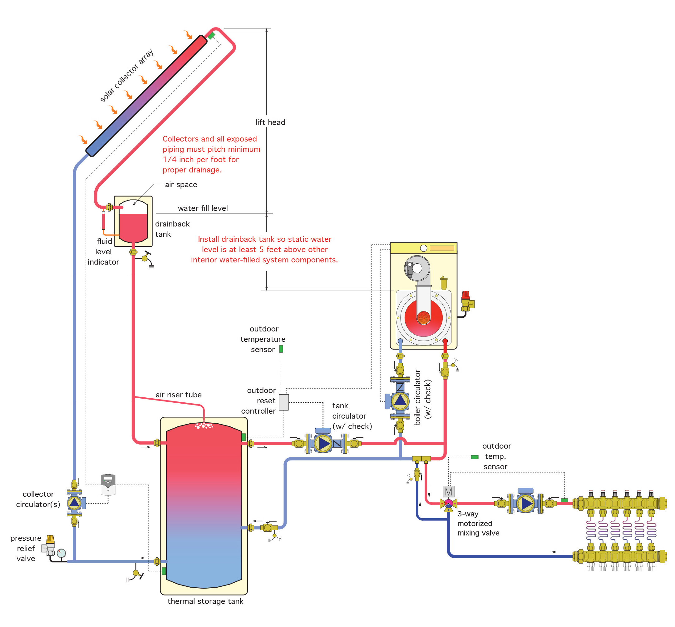
The solar subsystem uses a drainback feature instead of antifreeze for freeze protection. The drainback tank is located as high as possible within a heated space to minimize both the head required by the collector circulator as well as to minimize drainback volume. The liquid level in the drainback tank is what determines the pressure on the whole system, so it should be at least 5 feet higher than any of the other components within the system (see the notes in red on the diagram). An air riser tube directs any air that accumulates at the top of the thermal storage tank to the drainback tank, rather than eliminate it from the system piping. This is a closed-loop system; eliminating air from it will drop the system’s pressure and possibly cause circulation and corrosion problems. Float-type air vents should be placed at all high points in the system.
It should be noted that drainback systems should not have automatic makeup water connections. The operation of automatic air vents, in conjunction with automatic makeup water, would result in vented air being replaced with water, and eventually the system would become “waterlogged”. Although this practice would be desirable in conventional hydronic systems, it would undoubtedly lead to system freeze-up and costly damage. It is imperative that the correct air volume in the drainback tank be maintained. The drainback tank’s air volume must be periodically checked. Small volumes of water may have to be added manually to replace volume that is lost through the operation of the high point air vents.
Active Solar Supplying Forced Air Space Heating
Even though the majority of homes in Canada are heating using forced-air systems, an active solar system can be incorporated to assist the energy load. Figure 3 below shows an active solar system in conjunction with a forced-air furnace.
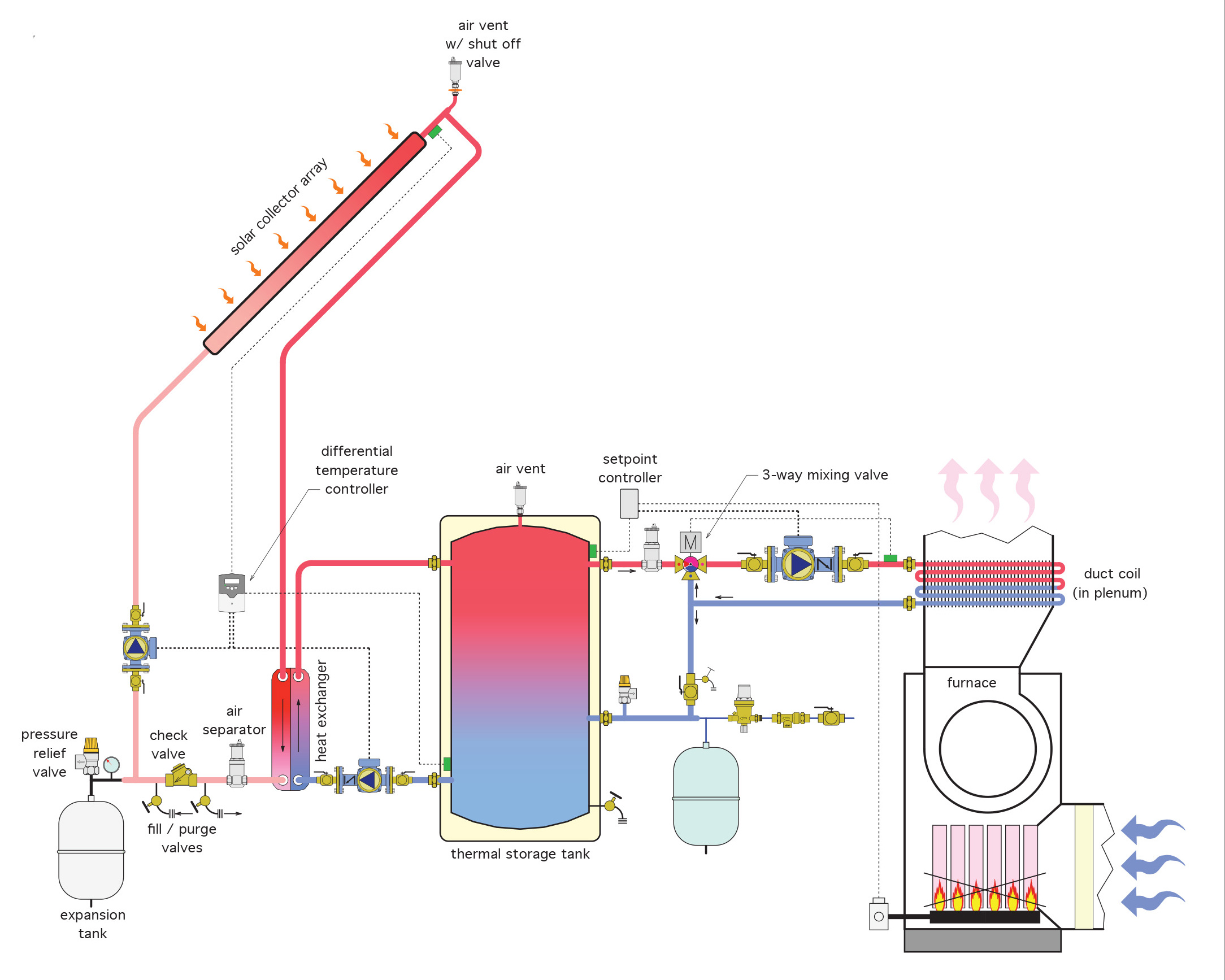
The solar section operates with an antifreeze mixture on one side of a stainless-steel plate heat exchanger. When the differential controller senses more heat at the collectors than at the tank, the collector circulator is turned on to move water through the supply side of the heat exchanger. This is a closed loop so requires an expansion tank.
On the load side of the heat exchanger, 100% water is moved from the heat exchanger to the thermal storage tank. On a call for heat, a setpoint temperature control senses if there is enough heat at the tank, and if so, turns on the circulator which feeds the coil above the furnace while simultaneously powering the furnace fan motor. A 3-way valve keeps excessively hot water from reaching the coil by mixing hot supply water with return water from the coil. When the water temperature in the storage tank gets too low, the setpoint controller turns off the circulator and allows the furnace burner to fire.
This relatively simple system is easily adapted to an existing forced-air system. A key consideration is that the duct coil should be adequately sized to allow as low a water temperature as possible through the coil.
Combined Solar Space and Domestic Water Heating
These systems are often known as “solar combi-systems”. If a solar system was being planned as the main source of space heating, it just makes sense to add in the capability for domestic water heating as well, given that solar thermal systems are best suited for that purpose. If a boiler is the backup source for the space heating, it can also be easily worked into the plans as the backup for the domestic heat as well. While not endless, the options for uses and configurations of system hardware components are varied. On the solar side, drainback versus antifreeze, internal versus external heat exchanger are choices to be considered. On the load side, some of the choices are single tank versus two-tank, hydronic radiant versus forced air, on-demand versus conventional boiler, and 3-way versus 4-way mixing valves. We will look at 2 options for combi-systems and discuss their design considerations.
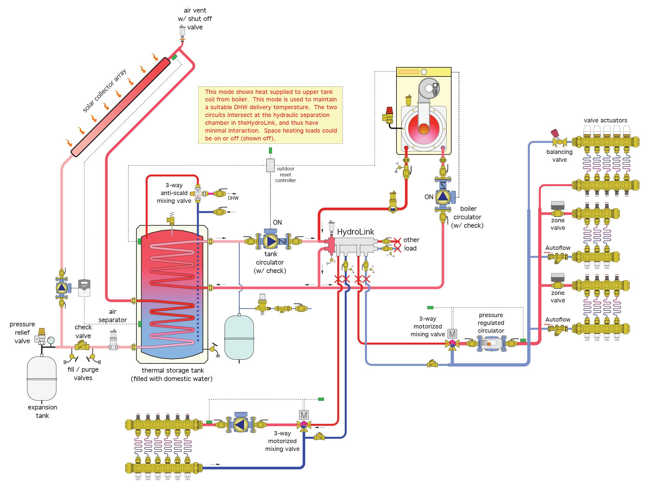
One example of a state-of-the-art combi-system is shown below in Figure 4. We’ll label it “Combi-system 1”.
The solar side is an antifreeze-protected closed loop with the usual components:
- a differential temperature controller sensing tank vs collector temperature
- a collector circulator
- an expansion tank
- a check valve
- purge/fill valves
- an air separator
- a high point air vent with shutoff valve
- a solar collector array
- a coil-type heat exchanger mounted within a storage tank
When the differential temperature control senses more heat at the collectors than in the tank, the circulator is powered and antifreeze fluid is moved from the collector array to the tank until the temperature differential between the two points is very near to being equal, at which time it shuts off.
On the load side, the components of this system are:
- a single two-coil tank (heat exchanger) with the upper coil connected to the space heating fluid, the lower coil receiving heat from the solar array, and domestic water surrounding both coils
- an expansion tank and makeup water components
- a hydraulic separator (“Hydrolink” by Caleffi)
- an anti-scald (tempering) valve on the domestic hot water supply from the tank
- a primary loop, with circulator, connecting the tank coil and “Hydrolink”
- an on-demand, high-efficiency, condensing boiler on a secondary loop
- secondary loops consisting of low-temperature radiant manifolds with 3-way mixing valves, zone valves, balancing valves and dedicated circulators
- an outdoor reset control connected to the top of the tank and the boiler
On the load side, the outdoor reset control constantly monitors the temperature at the top of the tank. If it falls below a minimum setpoint, the controller starts the primary pump along with the boiler and the boiler loop’s circulator. If sufficient heat exists at the top of the tank, the boiler loop remains off.
On a call for heat from one of the space heating zones, the circulators for that zone and the primary loop start. Heat is drawn from the tank’s upper coil to supply the primary loop and hydraulic separator. The connections to the space heating circuits are taken from the hydraulic separator to ensure that the operation of one secondary loop doesn’t affect the operation of other circulators on the system. The zone’s 3-way motorized valve is operated by an outdoor reset control that is actually reading the outdoor temperature and automatically raising or lowering the loop temperature in response to the outdoor temperature rising or falling. This ensures that the coolest water possible that will provide heat is applied to the radiant zones, thereby maximizing efficiencies.
If the tank’s temperature falls while space heat is being supplied, the boiler loop is energized and adds necessary heat to the primary loop.
The anti-scald valve on the domestic hot water supply, taken from the space around the tank coils, operates to ensure no scalding water reaches the faucets.
When domestic water and space heating water are supplied from the same heat source, a standard practice is to employ “priority” controls. The strategy of priority control is to stop the space heating system whenever there is need for adding heat to the domestic hot water storage vessel. The rationale here is that most buildings are insulated well enough that they can withstand short periods where the heating system is concentrating on domestic water while ignoring space heat deficiencies. There are timers involved in these controls so that the “off” period for space heat isn’t too prolonged – at a certain point, the controls will switch over to satisfy space heat needs while ignoring the domestic water demand. Once the space heat demand has been satisfied, the heating of domestic water can once again take priority.
Figure 5 below is a second example of a combi-system.
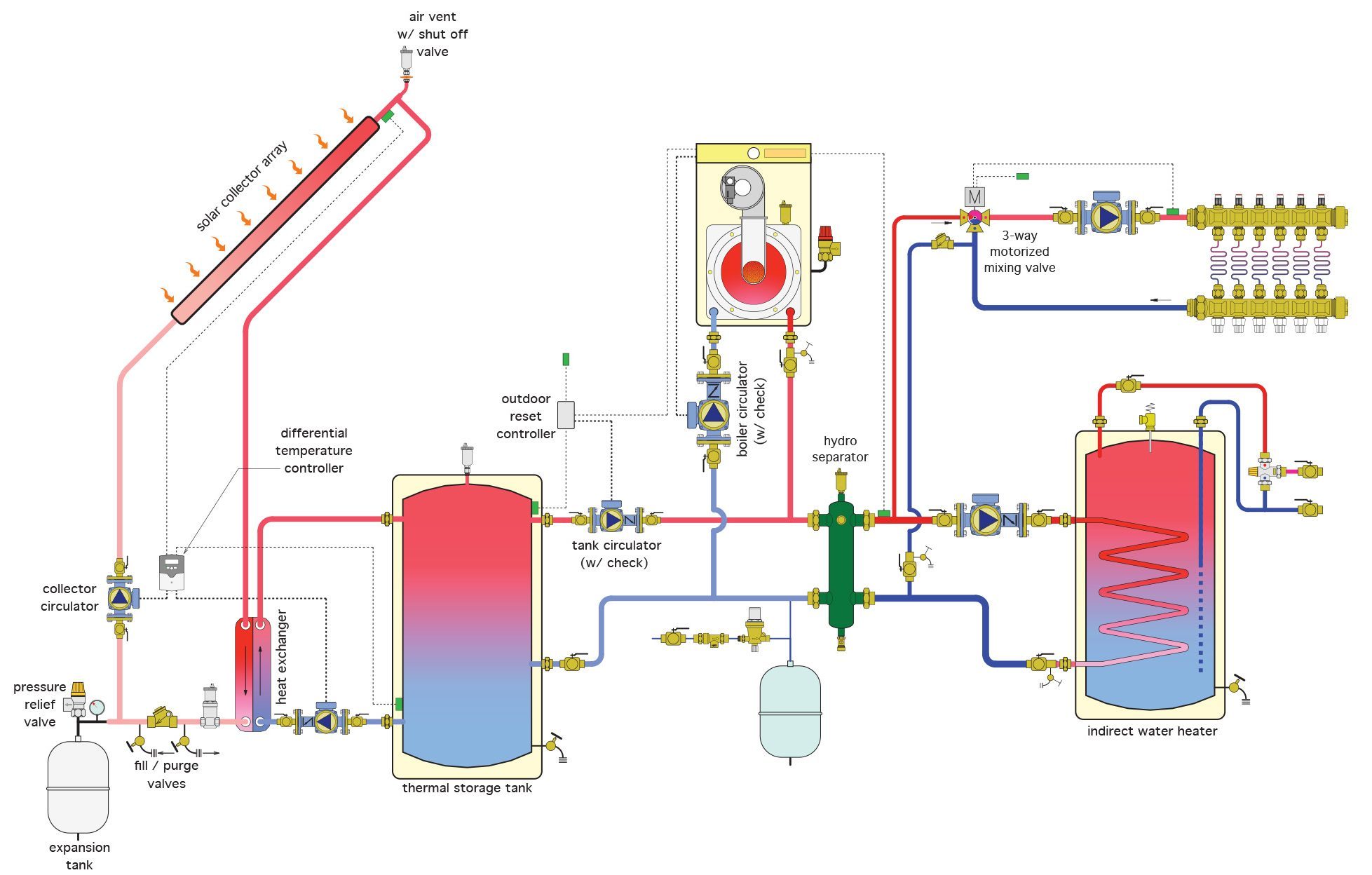
On the solar side, it consists of an antifreeze-protected loop having:
- a solar collector array
- a stainless-steel plate heat exchanger
- a differential temperature controller
- a collector circulator
- an air separator
- purge/fill valves
- an expansion tank
- a check valve
The differential temperature controller constantly monitors the tank and collector temperatures and starts the collector circulator when there is more heat at the collectors than at the tank, circulating an antifreeze solution through the heat exchanger .
The load side of the system consists of:
- the load side of the heat exchanger
- a solar thermal tank
- a tank circulator with built-in check valve
- an on-demand boiler with circulator
- radiant manifolds with 3-way motorized mixing valves and outdoor reset control
- an indirect domestic storage-type water heater
- a hydraulic separator
- an expansion tank with makeup water components
An outdoor reset controller constantly monitors the temperature at the top of the thermal storage tank. If auxiliary heat is needed, the controller energizes the boiler, its circulator and the tank circulator which work to maintain temperature in the hydraulic separator. On a call for heat by a radiant manifold, its circulator is powered to pull heated water from the hydraulic separator. The motorized 3-way mixing valve tempers the hot water with cool manifold return water in reaction to the outdoor reset control’s signal. This automatically adjusts the temperature of the water delivered to the radiant system to correlate to the temperature outdoors.
On a call for heat from the domestic water tank, the circulator for the tank’s coil turns on and pulls water from the hydraulic separator. The domestic hot water leaving the tank passes through the anti-scald valve, which adds cold water to the flow if necessary in order to keep the hot water delivered to the faucets within the allowable temperature limit according to governing codes.
These are only two of many possible variations within the realm of combination space and domestic water heating.
Now complete Self-Test 3 and check your answers.
Self-Test 3
Self-Test 3
- Which one of the following is not a principle to be considered when using solar for space heating?
- Space heating systems that operate using low-temperature water will yield the highest collector efficiency
- All solar equipment must be protected from freezing during periods of solar inactivity
- Conventional energy source should remain “off” until immediately needed
- The need for cross connection control is never a consideration
- Which space heating system is ideally suited to an active solar system?
- Hydronic baseboard wallfin
- Hydronic radiant floor
- Electric radiant floor
- Forced warm air
- Which one of the following is not used to ensure hydraulic separation between primary and secondary circulators in a hydronic system’s primary loop?
- A “Hydrolink”
- Closely-spaced tees
- A 3-way mixing valve
- A hydraulic separator
- What determines the system pressure in a closed loop drainback system?
- The liquid level in the drainback tank
- The liquid level in the heat exchanger
- The liquid level in the collector array
- The liquid level in the boiler
- Which one of the following should a drainback system not contain?
- A circulator
- An air riser tube
- A pressure relief valve
- An air vent and automatic makeup water
- On a solar system suppling heat for a forced-air system, what component prevents excessively hoy water from reaching the coil in the furnace’s supply plenum?
- A T&P relief valve
- A 3-way mixing valve
- A pressure relief valve
- A circulator isolation valve
- In Figure 24, what provides the hydraulic separation between the primary and secondary loops?
- The “HydroLink”
- A heat exchanger
- The tank circulator
- The water makeup valve
- What is the control strategy called that shuts off space heat when domestic water needs to be heated in a combi-system?
- Priority
- Stagnation
- Preference
- Primary-secondary
- What is the control that is normally used to automatically adjust the water temperature to a radiant floor system, depending on the temperature outdoors, but can also be used to monitor the water temperature at the top of the thermal storage tank?
- Automatic temperature adjustment
- Thermal storage tank reset
- Outdoor reset
- Indoor reset
- On which side of a hydronic system the radiant floor panels be found?
- The load side
- The source side
- The thermal side
- The exchange side
Check your answers using the Self-Test Answer Keys in Appendix 1.
Media Attributions
- Figure 1 Solar supplementing a radiant floor system © Caleffi Hydronic Solutions. Used with permission.
- Figure 2 Drainback system with radiant floor heat and modulating condensing boiler © Caleffi Hydronic Solutions. Used with permission.
- Figure 3 Active solar and forced-air furnace © Caleffi Hydronic Solutions. Used with permission.
- Figure 4 Combi-system 1 © Caleffi Hydronic Solutions. Used with permission.
- Figure 5 Combi-system 2 © Caleffi Hydronic Solutions. Used with permission.
