Learning Task 4
Solar Installation Considerations
Probably the single most important consideration in a solar system is the placing of the collector(s), with any possibility of shading being the determining factor. Collector arrays located so that they have direct sun playing on them all day long, if it is present, is certainly the situation to strive for. Properly assessing every potential site for possible shading from trees, hills and other objects is extremely critical and can be challenging, given the conditions and time of year that the assessment is being done. Special tools are available that can assist in predicting the possible occurrence of shading at any specific location. One such tool, called a “solar pathfinder”, is shown in Figure 1 below.
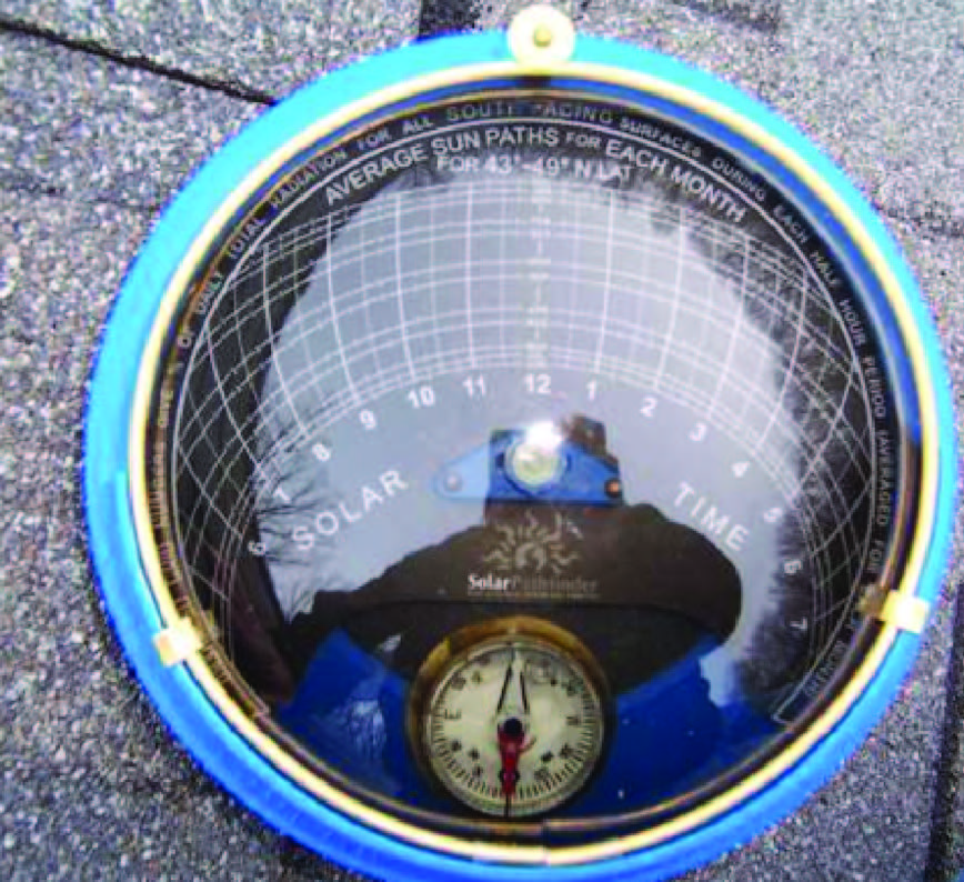
This device is placed at the location being considered. After being properly leveled and oriented according to the local latitude and longitude coordinates, it will use the reflections of nearby obstructions through its clear dome and project them onto a special chart that predicts the shading effects through the entire year. Because direct solar intensity varies throughout the day, some minimal shading in early morning and late afternoon isn’t as critical as it is between the hours of 9am and 3pm, when no shading should be encountered.
While collectors are manufactured to withstand severe weather conditions, if collector arrays are to last as long as the collectors themselves, the installation base they are mounted on must be sound. Collectors can be mounted on roofs (most common) or at ground level, as seen in Figure 2 below.
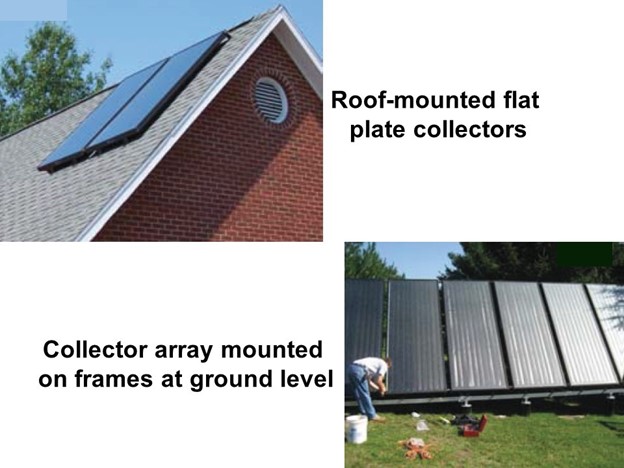
Collectors mounted on a frame that is affixed to a roof may have little ability to be positioned at the optimum angles for direct solar energy collection, such as seen in the upper picture in Figure 2. A ground-level array, as seen in the lower picture in Figure 27, can be better positioned for energy collection purposes but will take up more space than the roof-mounted array. If collector positioning is critical and ground area is limited, special engineer-designed pedestals can be an option. Figure 3 below shows a solar PV (photovoltaic) pedestal-mounted array that is positioned for optimal solar energy collection.
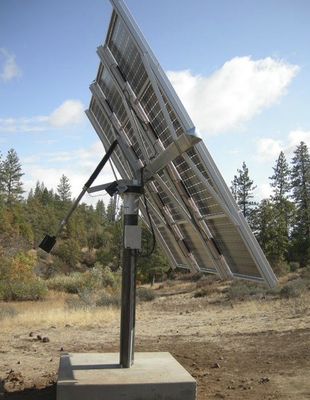
This option raises the array off the ground, allowing for optimum positioning for maximum solar gain while not taking away as much ground area. However, support and protection for the supply and return piping will be more difficult.
While solar collectors should be installed level, all solar piping should be pitched to allow adequate drainage when required, as well as to allow air to be vented through the high point on the top header (if the system isn’t of the drainback variety). Good piping insulation is also critical. A good foam rubber type insulation, without a split feature, is the best choice, although its installation must be done at the time the piping is being joined together. This can make the installation more difficult but certainly not impossible. Fewer gaps in the insulation allows less air movement around the pipes and provides a better insulation level. Weather and birds, such as crows, can wreak havoc on foam insulation and it may require a plastic or aluminum cover to protect it. Ideally all joints in the insulation should be sealed.
Collector Mounting Angles
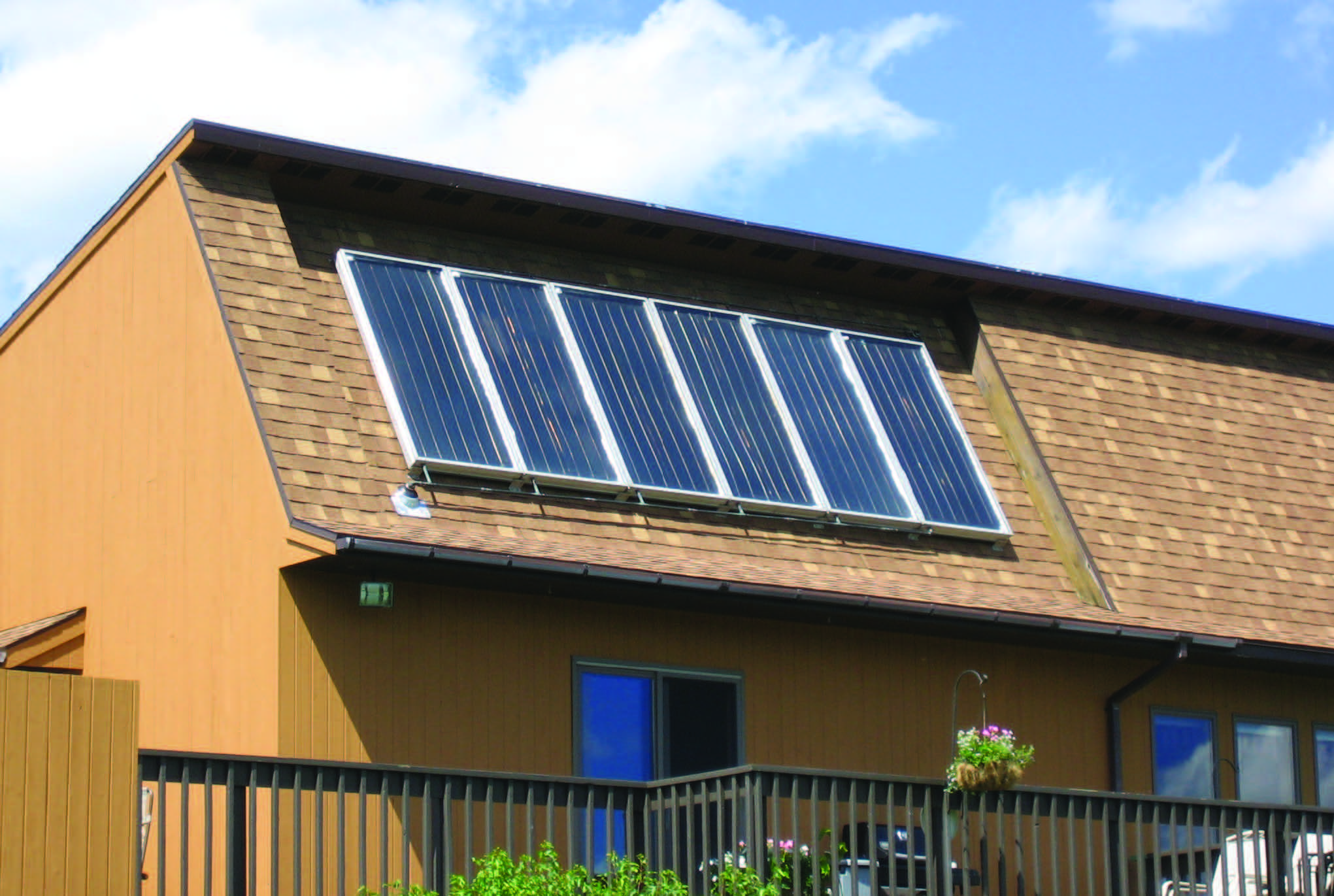
In the northern hemisphere, the optimum azimuth angle (check back to Figure 2) is 180°, which means the solar array faces directly polar south. Studies have shown that the azimuth angle can vary by as much as 30° east or west of polar south without having much effect on the annual solar energy gain. What does have a large effect is the solar collector angle or horizontal “tilt” of the array (again, check back to Figure 2). Studies suggest that collectors used for solar domestic water heating operate best at an angle equal to the local latitude. For space heating purposes, they suggest a solar angle of the local latitude plus 10 to 20° to allow better energy collection during late fall, winter and early spring. In order to satisfy both requirements, it is generally acceptable to install collectors at a solar angle of local latitude plus 15°. For example, an array in Kelowna, with a latitude of 49.8880°N should be tilted at approximately 65° from horizontal and an azimuth angle of polar south. If possible, construction design may be altered to accommodate roof-mounted collectors by increasing roof angles in that area. Figure 4 below shows an array that supplies both space and domestic heating. The roof angle was increased to 60° in a geographic location at 44°N.
Equipment Installation Considerations
Solar equipment in the mechanical room should be carefully arranged so as to provide adequate access for servicing and minimize loss of available space. A neatly arranged, well thought-out placement of equipment and piping will project an air of professionalism and contributes to good aesthetics. Tank size and placement is critical. Space limitations may require the use of multiple smaller tanks rather than one large one. As well, they may have to be small enough to fit through a doorway if replacement is needed. Floors must be constructed strong enough to bear the weight of the full tanks, and ceilings may have to be utilized for the support of horizontal piping and pumps. Labeling of components is important if a service technician has to decipher the layout, and a simply-worded “sequence of operation”, which spells out exactly how the system works, should be left in a conspicuous place in the mechanical room. This alone is a huge boon to any service tech.
As far as piping materials are concerned, copper is the piping of choice for these systems, and today’s pressing technology is preferred due to the lack of flux and other contaminants such as solder potentially plugging the system. Flushing flux from piping and components with cold water rarely achieves good results, although the flux will thin and coat the inside of the system once the system heats up, but it will still remain there, so pressed fittings alleviate that situation.
As with any other fluid mechanical system, solar systems must be tested according to the codes and regulations being adhered to, as well as to manufacturers’ specifications. This should be done with the collector array covered, or at night, to avoid unwanted heat during the process. After testing, the system should be flushed according to good piping practices before it is put into operation, done as well at night or without the collectors absorbing heat. Some literature suggests a flushing solution of 1% to 2% trisodium phosphate (TSP) to aid in the removal of dirt and debris.
Testing, commissioning and final report checklists are available to assist the technician in ensuring that no important points of these procedures are overlooked.
Active Solar System Performance Estimates
There are so many variations of collector types, geographic locations, equipment types, etc. that an estimation of the performance of a solar thermal system will be very difficult for any contractor or installer. Fortunately, software programs exist that can be helpful when proposing an installation to a potential customer. Three of the most common software tools that simulate the performance of a solar system are:
- F-chart. This was developed by the University of Wisconsin and has been used for technical and economic analysis of active solar space and domestic water heating for over thirty years.
- Tsol. This simulation software was developed and intended for use in Europe.
- RET Screen. Developed by Natural Resources Canada (NRC), RET Screen is a powerful simulation software tool that can be used to study the technical and economic feasibility of active solar energy systems, as well as several other types of renewable energy technologies. This software is available as a free download from RETScreen.
A common method of expressing the thermal performance of an active solar system is by stating the percentage of the load met by the solar energy on a month-by-month basis, known as solar fraction. The monthly totals can also be combined to yield an annual solar fraction. Solar fractions are usually expressed as a percentage. Larger collector arrays and larger storage tanks will yield larger solar heating fractions in all locations. While installing large arrays and large tanks may seem like the best idea, there will be a point where the economic viability of oversizing equipment will not be present, and the installation of smaller components may yield a better return on investment over the life of the system. Again, the only way to obtain a fair economic analysis is through the use of computer simulation software.
Typical Solar Thermal Equipment
Listed are the components that accompany collectors and are commonly found in active solar thermal systems. Their use is much the same as if they were installed in a hydronic heating system, and as such, you may already be familiar with them.
Heat Exchangers
These are identical to those used in a hydronic system. There are two types commonly used in solar systems – brazed plate and indirect-storage.
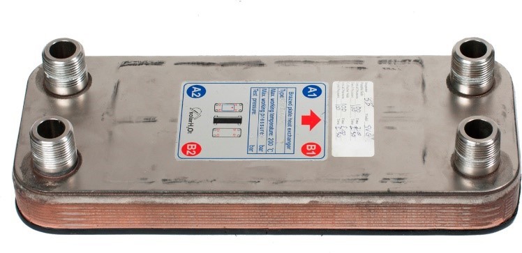
Brazed Plate Heat Exchangers
These have an enormous heat exchange capacity relative to their size due to their small-diameter fluid passages in relation to a large heat-transfer surface area. Fluid paths through them are always piped in a counterflow configuration for greatest heat transfer. These have a high temperature differential at low flow rates through them.
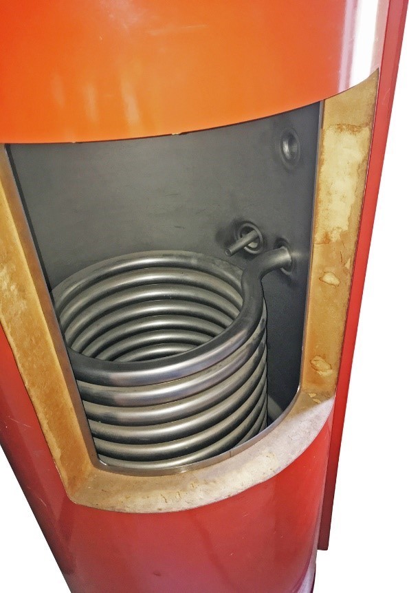
Indirect Storage-Type Heat Exchangers
These are simply a storage tank with one or two internally-mounted coils. Typically, non-potable heating fluid is circulated through the coil(s) and potable water surrounds the coil(s). These typically have lower temperature differentials and higher flow rates than the brazed plate heat exchangers, and are usually meant to heat and store domestic potable water but can be used for any purpose. A cutaway of a single-coil indirect heat exchanger is shown in Figure 6 below.
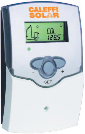
Differential Temperature Controller
This electronic control constantly compares the temperatures at its sensor locations and will send power to a circulator to add heat to the desired location.
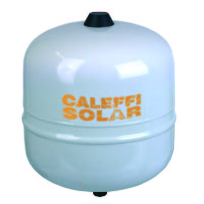
Expansion Tank
These are constructed and operate identically to those used in a hydronic heating system. They allow the fluid in the system to expand and contract in reaction to the heating and cooling of the system fluid, without appreciably causing a change in system pressure.
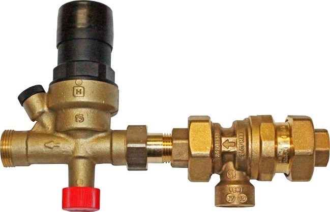
Water Makeup Station
Normally found on the load side piping of a closed loop, the makeup water station contains a backflow preventer and a pressure reducing valve. Other components that can be found in a water makeup line are a pressure gauge, bypass piping and a manual shutoff valve.
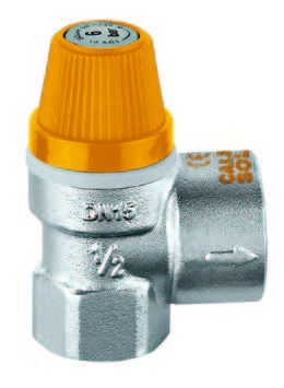
Pressure Relief Valve
Used to limit pressure in the primary circuits of closed-loop solar thermal systems, these valves open to release fluid to atmosphere when the calibrated pressure in the piping is reached, preventing system pressure from damaging system components.
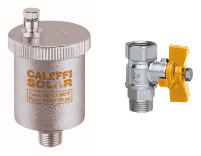
Float-Type Air Vent and Shutoff
These are used at the high point of the solar array in a closed loop.
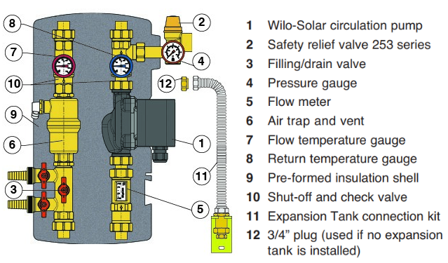
Solar Pump Station
A solar pump station is a compact insulated box containing various common components found in a solar thermal system. The station simplifies and speeds up the installation process.
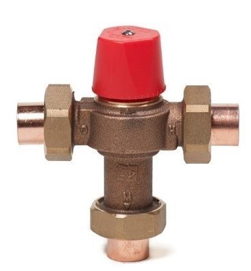
Thermostatic Mixing (Anti-Scald) Valve
These valves are installed on the domestic hot water line leaving the tank. They will mix cold water with potentially scalding water so that the water temperature to the faucets stays within allowable pre-set limits (usually 120°F or 49°C).
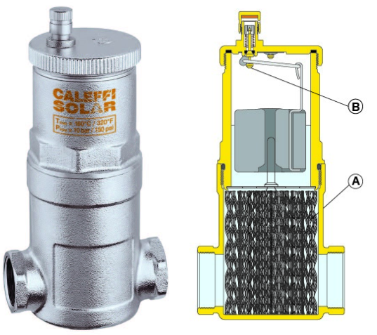
Air Separator
The inside of an air separator, also called a “microbubble resorber”, is composed of a set of metal screen surfaces arranged like spokes (A). This screen creates a swirling motion to assist the release of microbubbles from the solution and their adhesion to the metal screen. The bubbles join together and increase in size until the hydrostatic force exerted on the air bubble increases to overcome the force of its adhesion to the screen. Next, they rise to the top of the chamber where they are released by the built-in float-operated automatic air vent valve (B).
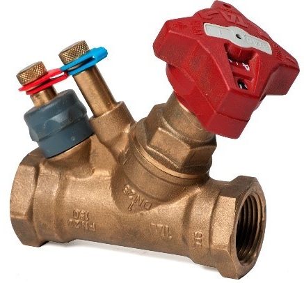
Flow Balancing Valves
These are identical to those used in a hydronic heating system, commonly known as “circuit setters”. They are a low head loss type of globe valve that has two ports for the attachment of a differential pressure gauge – one each on the upstream and downstream sides of the valve seat. The pressure differential read across the two ports, known as Pete’s plugs”, is referenced on a chart for that particular valve, to indicate the flow rate. The valve’s handle can be operated to allow an increase or decrease in flow rate as needed, and most have a locking feature so that inadvertent adjustment is avoided once it is set in the desired position. If possible, locate these valves on the discharge side of a pump, in order to avoid cavitation issues caused by mounting too close to a pump’s inlet.
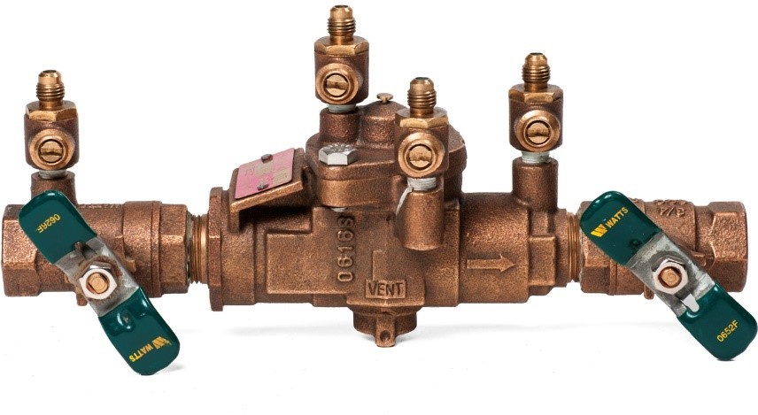
Cross Connection Considerations
Any time that potable water is connected to a liquid non-potable system, even with a pipe or tank wall between the two, there is a hazard of the mixing of potable and non-potable fluids through a break in the wall. Most plumbing jurisdictions in Canada are acutely aware of cross connection control regulations and standards, and have strict requirements that must be met. In areas within British Columbia that have cross connection control programs in place, the procedures for installing and testing backflow preventers as laid out by BCWWA (BC Water and Waste Association) apply. Otherwise, the enforceable regulations found in the BC Plumbing Code and/or National Plumbing Code of Canada or local bylaws must be followed. Always check with the governing Authority Having Jurisdiction for any cross connection control requirements before planning a solar thermal installation. When in doubt, the installation of an RPBA (reduced pressure backflow assembly) to protect the potable water system is never a bad choice (see Figure 16 below).
Now complete Self-Test 4 and check your answers.
Self-Test 4
Self-Test 4
- What is the single most important consideration in a solar thermal system?
- The placement of the heat exchangers
- The placement of the solar collectors
- The placement of the piping runs
- The placement of the circulators
- Between what hours of the day is potential shading of the collectors most critical?
- 5am to 11am
- 12pm to 5pm
- 9am to 3pm
- 1pm to 6pm
- What would be the issue of most concern when using an engineer-designed pedestal base to support a solar thermal array?
- Support/protection of piping
- Correct azimuth position
- Weight of the array
- Area of the array
- What protection should also be installed along with insulation for supply and return piping?
- Thermometers and pressure gauges
- Directional indicators for flow
- Aluminum or plastic covers
- A drip pan
- What is the optimum azimuth angle for collectors installed in the northern hemisphere?
- 45°
- 90°
- 145°
- 180°
- What is the optimal collector angle or “tilt” when used for domestic water heating?
- The same as the local latitude
- 10° to 20° less than the local latitude
- 10° to 20° more than the local latitude
- 45° to 180° more than the local latitude
- What is the preferred type of pipe or tube and joining method used in solar thermal systems?
- Steel pipe with welded connections
- Copper tube with pressed connections
- Copper tube with soldered connections
- Aluminum tube with pressed connections
- Which one of the following is a Canadian-based software program, developed to simulate and estimate the performance of a solar thermal system?
- “F-chart”
- “Tsol”
- “Aquasol”
- “RETScreen”
- What is the term “solar fraction” used to describe?
- The percentage of the month-by-month total energy load that is met by an active solar system
- The amount of ongoing cost of operation that the initial installation cost represents
- The percentage of time that the solar system is shut down for routine maintenance
- The percentage of time that the solar system is energized and operating
- Which one of the following would best a storage tank with one or two internal coils?
- A brazed plate heat exchanger
- A shell-and-tube heat exchanger
- An indirect storage-type heat exchanger
- A high ΔT, low flow rate heat exchanger
- Which one of the following devices should always be installed on the hot water outlet of any thermal storage tank that feeds the potable water system?
- A water makeup station
- A pressure relief valve
- A solar pump station
- An anti-scald valve
- Which one of the following devices contains “Pete’s plugs” that allow a pressure differential to be read across it?
- A differential temperature controller
- A microbubble resorber
- A pressure relief valve
- A circuit setter
- Whenever a cross connection may exist between a potable water system and the solar thermal system, which one of the following would be considered the best choice for protection of the potable system?
- An RPBA
- A DCVA
- An AVB
- A PVB
- Which one of the following devices, used in solar thermal systems, would normally not also be found within a typical hydronic heating system?
- An air separator
- A drainback tank
- An expansion tank
- A pressure relief valve
Check your answers using the Self-Test Answer Keys in Appendix 1.
Media Attributions
- Figure 1 Solar pathfinder © Caleffi Hydronic Solutions. Used with permission.
- Figure 2 Collector mounting locations © Caleffi Hydronic Solutions. Used with permission.
- Figure 3 Pedestal-mounted PV array © Caleffi Hydronic Solutions. Used with permission.
- Figure 4 Roof slope increased to accommodate optimum solar angle for collector array © Caleffi Hydronic Solutions. Used with permission.
- Figure 5 Stainless-steel brazed plate heat exchanger © Caleffi Hydronic Solutions. Used with permission.
- Figure 6 Differential temperature controller © Caleffi Hydronic Solutions. Used with permission.
- Figure 7 Differential temperature controller
- Figure 8 Expansion tank © Caleffi Hydronic Solutions. Used with permission.
- Figure 9 Water makeup station © Caleffi Hydronic Solutions. Used with permission.
- Figure 10 Pressure relief valve © Caleffi Hydronic Solutions. Used with permission.
- Figure 11 Float-type air vent and shutoff © Caleffi Hydronic Solutions. Used with permission.
- Figure 12 Solar pump station © Caleffi Hydronic Solutions. Used with permission.
- Figure 13 Anti-scald (thermostatic mixing) valve © Caleffi Hydronic Solutions. Used with permission.
- Figure 14 Air separator © Caleffi Hydronic Solutions. Used with permission.
- Figure 15 Balancing valve (“circuit setter”) with “Pete’s plugs” © Caleffi Hydronic Solutions. Used with permission.
- Figure 16 Reduced pressure backflow assembly (RPBA) © Caleffi Hydronic Solutions. Used with permission.
