Learning Task 4
Combined Heat/Cool Systems
To this point, we have focused mainly on the use of heat pumps for heating applications. There are far more design possibilities within that context, and to try to cover them all would be pointless. To that end, we will now look at a few options for the use of ground source heat pumps in heating/cooling scenarios.
The biggest advantage in the use of a reversible heat pump is its ability to provide both heating and cooling. Water taken to low temperatures for use in cooling operations is known as “chilled water”. While heating water can be utilized at low or high intensities (temperatures) depending on the intended size and type of emitter, there aren’t normally as many options available for the use of chilled water for cooling.
Firstly, if a building’s cooling system is meant to provide comfort for its inhabitants, it must lower both the air’s temperature and its moisture content. Most heat pumps are capable of producing chilled water in the 40°F – 60°F (4°C – 15°C) range, with some able to reach temperatures below 32°F (0°C). Such low temperatures are not only not necessary but they also negatively impact the cooling capacity and EER of the heat pump. It is seldom necessary to chill water to temperatures below 45°F (7°C), and temperatures greater than 60°F (15°C) will not effectively remove moisture from the air. Removing moisture from air is known as latent cooling and is a critical step in maintaining comfort conditions indoors.
Morning dew on a lawn is a visible indication that moisture from the air has condensed overnight when the outdoor temperature has dropped below a certain point. This point is known as the dew point, at which the air is said to be saturated, and any cooling of the air below this point will result in the water vapour condensing into water. This is the most important effect caused by building cooling that must be dealt with.
There is no singular dew point temperature; it changes with the air’s thermometer-measured (sensible heat) temperature, called the dry bulb temperature, and the relative humidity of the air. Because of the issue concerning condensation formation on surfaces conveying chilled water, radiant cooling is not often an option. High-tech, expensive controls would be needed for those systems to ensure that the chilled water temperature stays a few degrees above the dew point, which would need to be calculated at all times of cooling, while still ensuring it is cold enough to achieve the desired cooling effect. Radiant-cooled surfaces would actually be the interior surfaces of the building and would become wet. This means that, as far as the cooling (evaporator) side of a heat pump is concerned, air will be the medium being cooled.
Any piece of equipment that intentionally uses chilled water to lower the temperature of the air for cooling purposes is called a chilled water terminal unit, and the formation of condensed water on the surfaces of the heat exchanger within it, as just mentioned, is fairly unavoidable. Therefore, there must be means of collecting and disposing of this condensation. Chilled water terminal units will contain a drip pan for these purposes. Condensation forming on the surfaces of the chilled water heat exchanger will form droplets that will fall vertically into a pan made of corrosion-resistant material, usually plastic. The drip pan is then piped to a safe disposal location such as a hub drain or to outdoors. This is clear-water waste by definition and so can be disposed of almost anywhere, according to governing Plumbing codes. Sch 40 PVC is the material most commonly used for this purpose.
Figure 1 below shows two examples of chilled water terminal units.
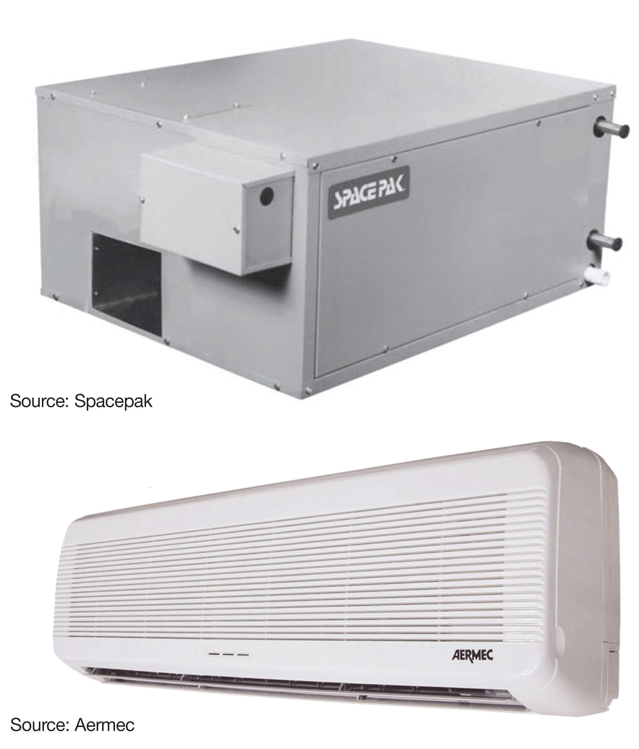
The upper image is of a unit that would likely be installed above a T-bar ceiling in a commercial building. The lower image is of the terminal unit in a “split” system. It is meant to be exposed, high on an outside wall, with the chilled water piping feeding it from a heat pump normally located outdoors in either a residential or commercial setting.
Any component of a chilled water system that can contact air will have a possibility of condensation formation on it, which will be problematic. Stained ceiling surfaces, puddles on the floor and mold and mildew will be the results of unwanted condensation. Therefore, piping and other components of the chilled water delivery system such as valves and circulators must be insulated and hermetically sealed. Any air leakage onto those components will result in water drippage and must be avoided. Foam-type insulation has proven to be the best material for this purpose due to its closed-cell structure, moisture resistance and ability to be sealed tightly. Figure 2 below shows piping using foam- type insulation.
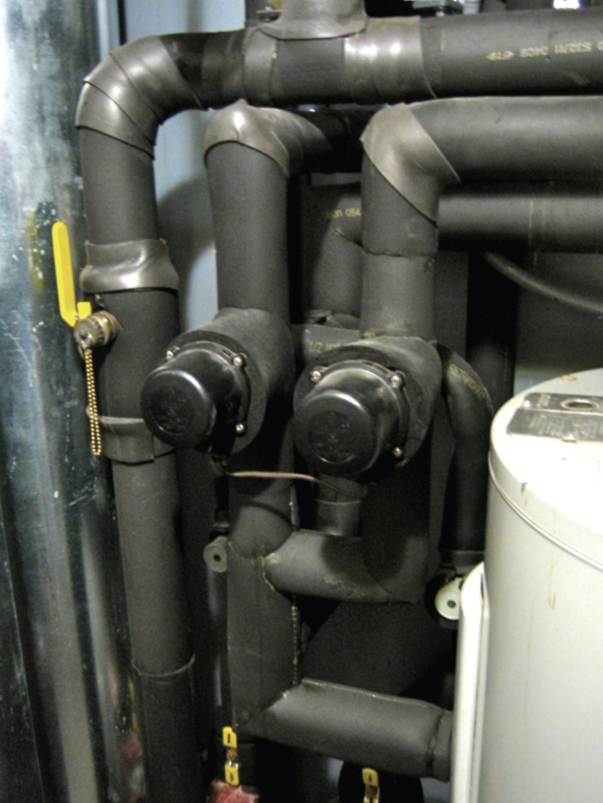
For proper operation, some piping components such as valve actuators and motors must remain uninsulated.
Domestic Water Heating
There are far too many options available for the use of reversible heat pumps to list in this learning module. For residential use, a heat pump is most often of the air-to-air variety based almost solely on the facts that:
- while radiant heat is the most comfortable means of delivering heat to occupants, it doesn’t match well with the budgets needed to fund the control systems required for radiant cooling through the same system
- most homeowners don’t have the budget for separate radiant-heat and convective (forced-air) cooling, and
- the use of two separate heating and cooling systems takes up more space than homeowners and contractors are willing to sacrifice
Consequently, reversible heat pumps used in residential buildings are mainly of the air-to-air type. Regardless of the type of system used, the heat that is rejected by the system in its cooling mode can be diverted and used to heat domestic hot water, as shown in Figure 3 below.
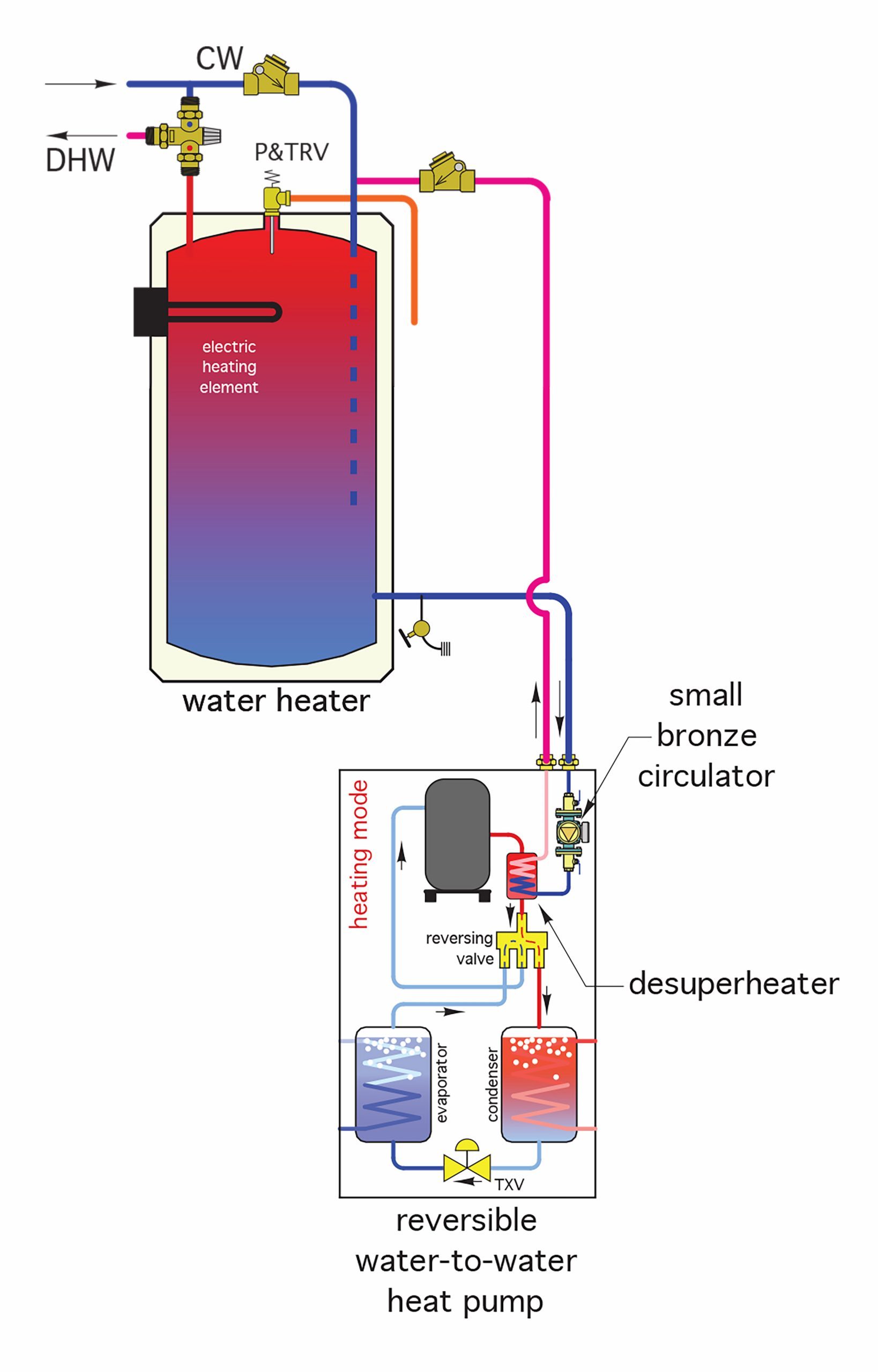
In the figure above, the heat that would normally need to be rejected to the condenser through the cooling process is instead diverted to a “desuperheater”. This heat exchanger instead transfers the rejected heat to the water in the tank. In effect, this heat is truly 100% “free heat”.
Figure 4 below is an example of a system that is fairly elaborate, in that it has captured all the aforementioned aspects of the use of reversible water-to-water (geothermal) heat pumps into one system.
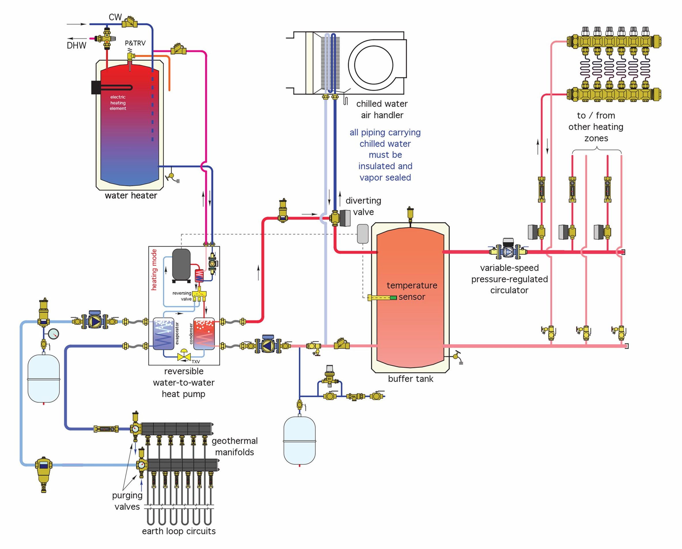
It shows a manifolded ground source (geothermal) field, a buffer tank, radiant floor heating, convective (forced air) cooling, and domestic hot water generation.
Filling/Flushing
Unwanted debris in any system can cause problems, and so, just like every mechanical piping system, an earth loop piping system must be flushed before being commissioned. Flushing using a high-velocity stream of water is the preferred means for debris removal and should be done in an orderly fashion. The order should be:
- Fill and flush the earth loops and exterior piping
- Fill and flush the interior portions of the earth loop piping and heat exchanger, then
- Simultaneously purge the earth loops, exterior and interior piping
Once flushed, the earth loop side of the system can have antifreeze added if required.
A valved earth loop system will need to be purged in a different manner than one that doesn’t have valved earth loops. For a valved system, each loop can be individually isolated and purged at a rate of at least 2 feet per second. This rate has been proven to be effective at removing air and debris from the piping, however, the system’s installed circulator will usually not be able to move water at a sufficient velocity and quantity to achieve proper purging results. Therefore, a powerful high-capacity purging pump, as shown in Figure 5 below, is temporarily connected to the piping for both valved and non-valved configurations. Sometimes called a “purge cart” or “purge barrel”, the setup consists of a pump, which is similar to one used for pools or shallow wells, a barrel that holds at least 30 gallons of liquid, and large-diameter flexible hose connections.
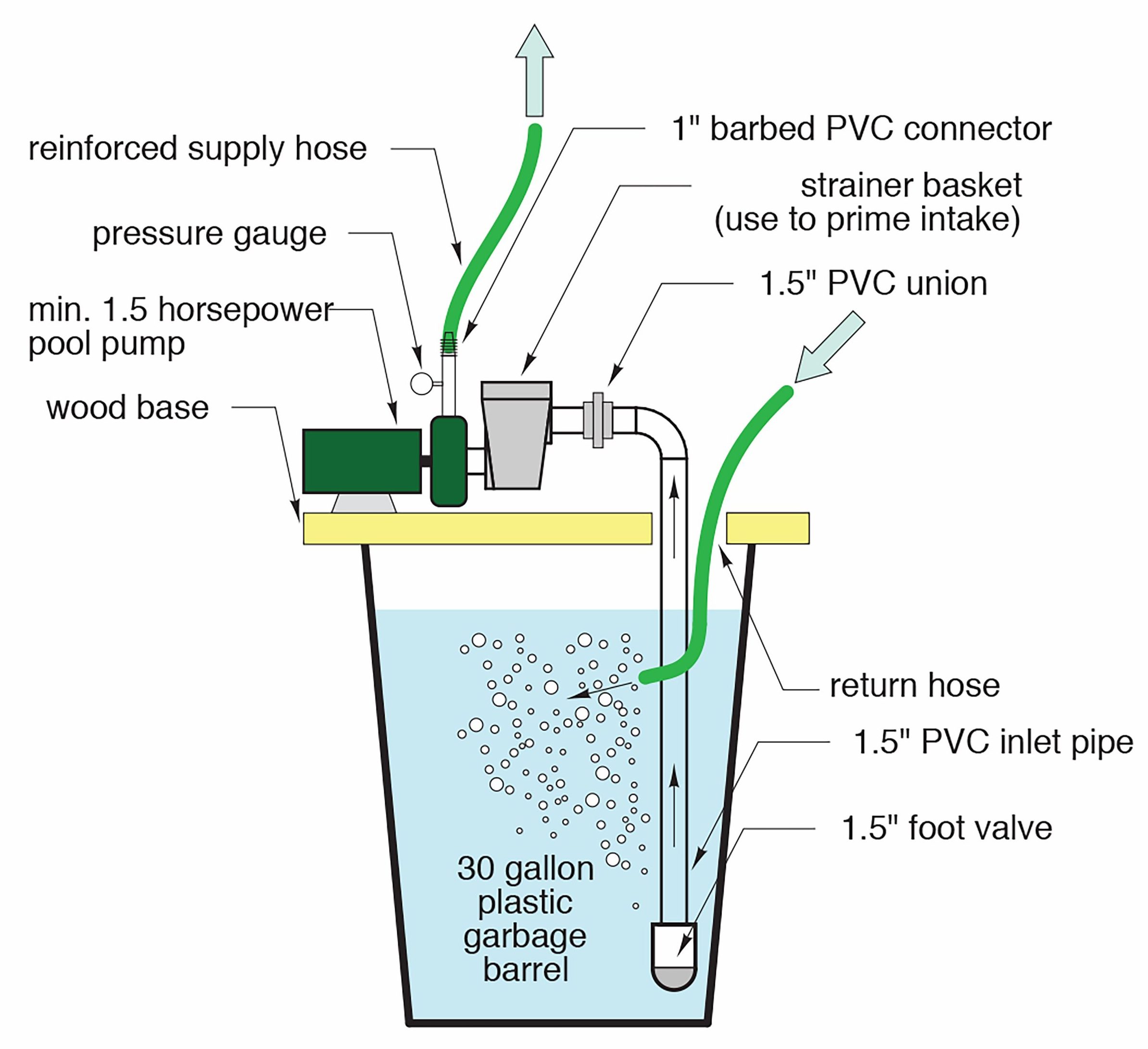
The pump will draw liquid from the barrel, push it through the piping at a high velocity and return it into the barrel, where any entrained air will be seen as bubbly water. For a valved system, loops are individually purged through the purge point connections installed in every loop until there are no indications or air bubbles in the return flow. For a system with no valves, where loops are connected to the mains in a reverse-return configuration and are inaccessible, the purge pump is connected to purge points in the supply and return mains. This system will take longer to purge, as water has to be pushed through the entire system and returned to the cart. Figure 6 shows potential purge flow rates in GPM for the various parts of a non-valved system.
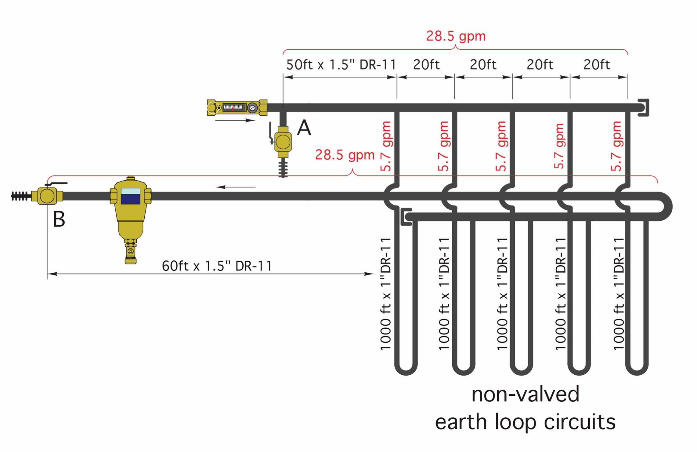
The flow rates in gallons per minute for three common sizes of loop piping are:
- 3.6 GPM for ¾″ DR-11 HDPE tubing
- 5.7 GPM for 1″ DR-11 HDPE tubing
- 9.0 GPM for 1 ¼″ DR-11 HDPE tubing
As shown in Figure 6 above, the flow rate through the manifold will be the total flow rate through all the loops it serves.
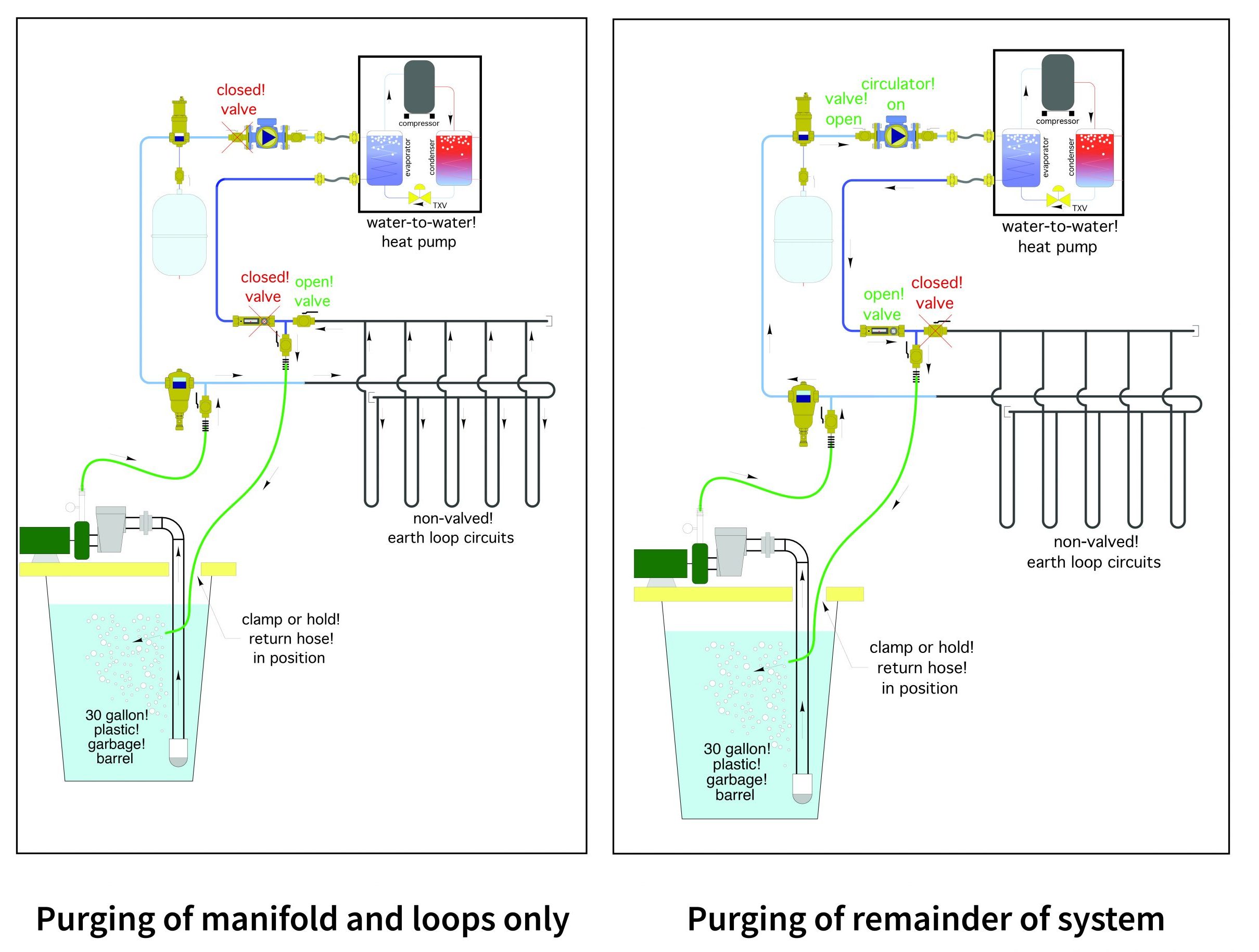
Figure 7 below illustrates connections and valve operation for first purging the loop and manifolds of a non-valved system, and then the remainder of its piping.
Once the purging is complete, the system can be started. It is recommended that, before adding antifreeze, the system is operated for a day or two using 100% water. This will allow any minor leaks to be dealt with, as well as ensuring that as much dissolved air as possible is removed from the system through the microbubble resorber and the dirt separator has taken care of any debris issues remaining after the purging process.
Adding Antifreeze
When freeze-protecting the earth loop system, its volume must be estimated fairly accurately in order to determine the correct amount of propylene glycol to be added. Manufacturers’ literature will publish the volume that one foot of their piping will hold, so all lengths and sizes of pipe must be recorded at the installation phase for this purpose. The volumes that heat exchangers and other components will hold are fairly small as compared to those in the manifolds and loops but must be added in nonetheless. The total volume of piping to be freeze protected must be known as well as the desired percentage of antifreeze solution. Most designers use a mixture in the range of between 15% and 25% glycol and water, with 20% as the median value. This low percentage will protect the piping as it is buried and shouldn’t be exposed to above-ground temperatures that can be much lower than those below-ground.
Once the system volume has been calculated, the amount of antifreeze to be added can be determined using the following formula:
Vantifreeze = % × (VS + Vmin) where:
- Vantifreeze is the amount of 100% antifreeze to be added, in gallons
- % is the desired mixture of antifreeze/water, expressed as a percentage
- VS is the calculated volume of earth loop piping system, in gallons, and
- Vmin is the minimum volume of fluid required in the barrel to allow proper pumping, in gallons
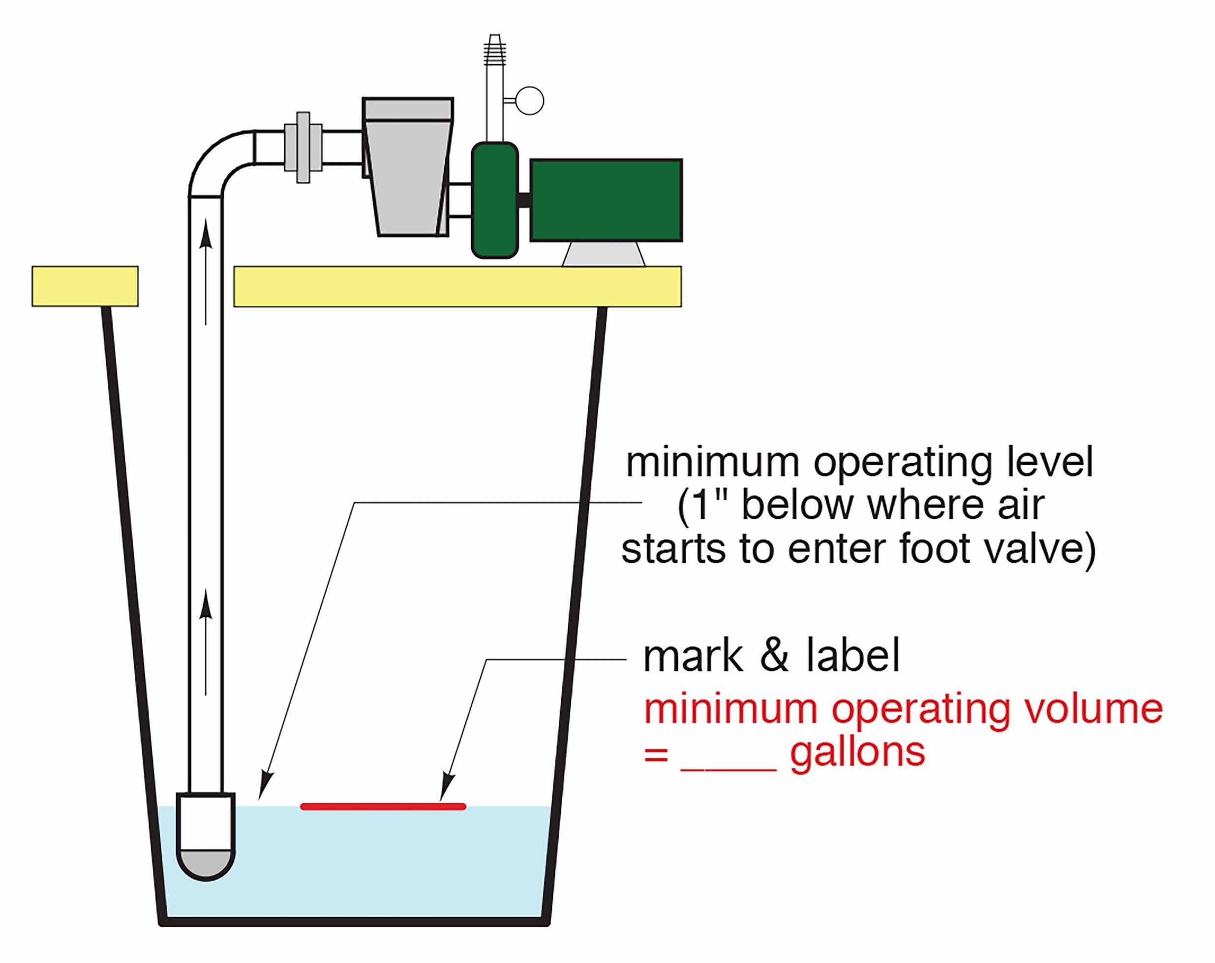
Figure 8 below illustrates the minimum fluid level in the purge barrel below which air might be drawn into the system, which must be avoided. This level is 1-inch above the intake level of the inlet fitting’s uppermost opening.
This amount is added to the calculated system volume in order to accurately determine the total volume of propylene glycol needed. As an example, if:
- The system volume is 124 gallons
- The minimum purge barrel operating volume is 2.5 gallons, and
- A 20% glycol mixture is desired, then
The percentage of 100% glycol needed would be determined using the equation shown above.
Volume = 20% × (124 gallons + 2.5 gallons)
Volume = 20% × 126.5 = 25.3 gallons of 100% glycol
To add the antifreeze to our example system, first drain from the filled system the amount of 100% water equal to 2.5 gallons. Then, add the 25.3 gallons of glycol to the purge barrel (this illustrates the benefit of using a barrel that holds at least 30 gallons). Turn on the pump and let the mixture circulate for at least 10 minutes in order to thoroughly mix the two mediums and to also rid the system of all but the dissolved air which will be handled by the microbubble resorber once the system is in operation.
The purge pump is also used to pressurize the system to its operating pressure, typically between 20 and 30 psi, by throttling partially closed the outlet valve being used for purging. This pressurizes the piping system including the expansion tank, which should be pre-charged to the desired system pressure. Once the appropriate system pressure is reached, the inlet purge valve is closed, the pump is shut off and the purge setup is removed. The fluid remaining in the purge barrel can be labeled as to its product used, its concentration and its date and stored for future use.
The procedures used for adding antifreeze to a valved system are the same as for a manifolded system.
Expansion Tanks for Earth Loop Systems
If an earth loop system is closed, there will be expansion and contraction of the fluid within it which are caused by changes in fluid temperature. This will affect the fluid’s pressure. An expansion tank is therefore a necessity in a closed-loop system. These are identical to those used in a hydronic heating system, and manufacturers will have sizing literature that is based on system volume and the net temperature change that it will undergo. Just as in a hydronic heating system, the amount of “acceptance volume” (amount of extra space the expanded liquid will occupy) needed will determine the tank’s size, and just like those heating systems, using a glycol solution rather than 100% water will have an effect on the size of tank needed. A system using a 20% glycol solution will typically need a larger expansion tank than one with 100% water. Earth loops will typically operate between as low as 30°F (−1°C) during the heating season to as high as 90°F (32°C) in the cooling season, with 50°F (10°C) usually used as the water temperature at the time of filling and commissioning.
Maintenance of Heat Pump Systems
Routine maintenance and performance checks should be done at least once a year, just like any other building mechanical system. The closed systems should stay that way – don’t dump, flush and refill any system unless necessary for repairs. Motors should be checked for excessive noise, vibration, heat and amperage. Any filters should be routinely changed throughout the season. Operating temperatures of the mediums should be checked to assure that the system is providing the expected temperature differentials at various locations within the system, such as the evaporator and condenser. Always check for fluid leakage and physical damage, and repair when noticed. Check for damaged or missing piping insulation and replace if necessary. Make sure any condensate drain pans are collecting water as they should, and ensure the piping from them isn’t blocked.
Now complete Self-Test 4 and check your answers.
Self-Test 4
Self-Test 4
- What is water that is taken to low temperatures and used for cooling known as?
- Cold water
- Chilled water
- Cooling water
- Condensed water
- What is moisture removal from interior air, for cooling and comfort purposes, known as?
- Latent cooling
- Sensible cooling
- Moisture depletion
- Dewpoint verification
- What is the most important consideration for cooling systems in order to avoid damage to the building?
- Fan locations
- Noise and vibration
- Thermostat locations
- Condensate collection and removal
- What is the condensate from a chilled water terminal unit considered to be?
- Sewage
- Rainwater
- Potable water
- Clear water waste
- Besides being insulated, what other protection is needed to prevent piping and associated fittings from causing condensation issues?
- They should be made of plastic
- They must always be concealed
- They must be hermetically sealed
- All piping should have drip pans below it
- What variety of heat pump is most common for residential use in Canada?
- Air-to-air
- Air-to-water
- Water-to-air
- Water-to-water
- In its simplest sense, what is a “desuperheater”?
- A heat exchanger
- An undersized heater
- A superheater that has been removed
- A component of an air-to-air heat pump
- What is the minimum suggested rate of purging (flushing) in order to remove unwanted debris and trapped air from earth loops and manifolds?
- 1 ft/sec
- 2 ft/sec
- 3 ft/sec
- 4 ft/sec
- What should be the minimum capacity of a purge barrel?
- 10 gallons
- 20 gallons
- 30 gallons
- 40 gallons
- What component of an earth-loop system will remove dissolved air from the piping, just as it does when installed in a hydronic heating system?
- A microbubble resorber
- An expansion tank
- A purge cart
- A float vent
- What is the median (average) percentage of glycol/water mixture used in antifreeze systems for heat pumps?
- 80% glycol, 20% water
- 50% glycol, 50% water
- 35% glycol, 65% water
- 20% glycol, 80% water
- Where is the lowest point (minimum water level) that liquid should be when using a purge barrel to flush or add glycol to the system, in order to prevent air from being drawn in with the liquid?
- 1 inch above the highest opening in the pump intake line
- 1 inch below the highest opening in the pump intake line
- 1 inch above the lowest opening in the pump return line
- 1 inch below the lowest opening in the pump return line
- Which one of the following components would have to be installed in any closed earth-loop system, to avoid issues caused by fluid temperature variations?
- A circulator
- A heat exchanger
- An expansion tank
- An outdoor reset controller
- For calculation purposes, what is usually used as the water temperature at time of filling the system?
- 30°F (−1°C)
- 50°F (10°C)
- 70°F (21°C)
- 90°F (32°C)
- Which one of the following choices would not be one that should be done routinely as part of regular system maintenance?
- Change any filters regularly
- Check for system leaks or damage
- Dump, flush and refill all closed-system piping
- Inspect motors for excessive noise, heat and vibration
Check your answers using the Self-Test Answer Keys in Appendix 1.
Media Attributions
- Figure 1 Chilled water terminal units © Caleffi Hydronic Solutions. Used with permission.
- Figure 2 Insulated piping and fittings © Caleffi Hydronic Solutions. Used with permission.
- Figure 3 Heating domestic water using “reject” heat © Caleffi Hydronic Solutions. Used with permission.
- Figure 4 A water-to-water reversible heat pump with domestic hot water generation © Caleffi Hydronic Solutions. Used with permission.
- Figure 5 Purge setup for earth loops © Caleffi Hydronic Solutions. Used with permission.
- Figure 6 Purge rates through a non-valved system © Caleffi Hydronic Solutions. Used with permission.
- Figure 7 Purging a non-valved system © Caleffi Hydronic Solutions. Used with permission.
- Figure 8 Minimum fluid level in purge barrel © Caleffi Hydronic Solutions. Used with permission.
