Learning Task 3
Closed-Loop Systems
A closed-loop geothermal system is a good choice when open-loop sources are either not available or are not allowable for various reasons noted above. Closed-loop geothermal systems either extract low-temperature heat from the earth (in heating mode) or reject it (in cooling mode) by circulating 100% water or a water-based antifreeze solution through a closed assembly of piping loops that are buried in the ground. These loops can be installed either vertically or horizontally.
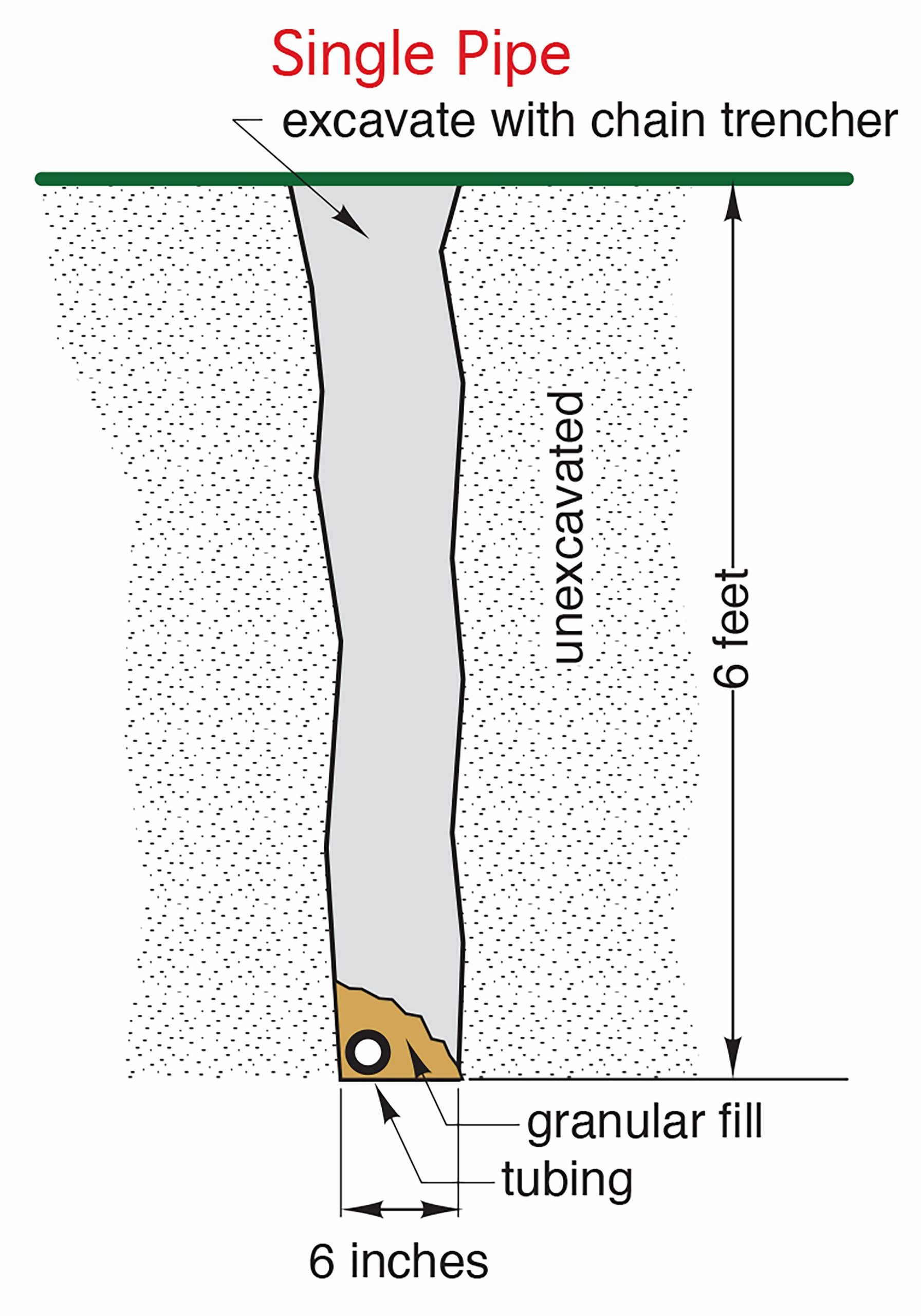
The choice of use of a horizontal earth loop installation is based on available area, soil conditions and availability of excavating equipment. Piping is buried 4 to 8 feet below the ground’s surface and can be installed with one, two or four pipes in a narrow trench or as a series of coils known as “slinkies” that are installed in a larger excavated area.
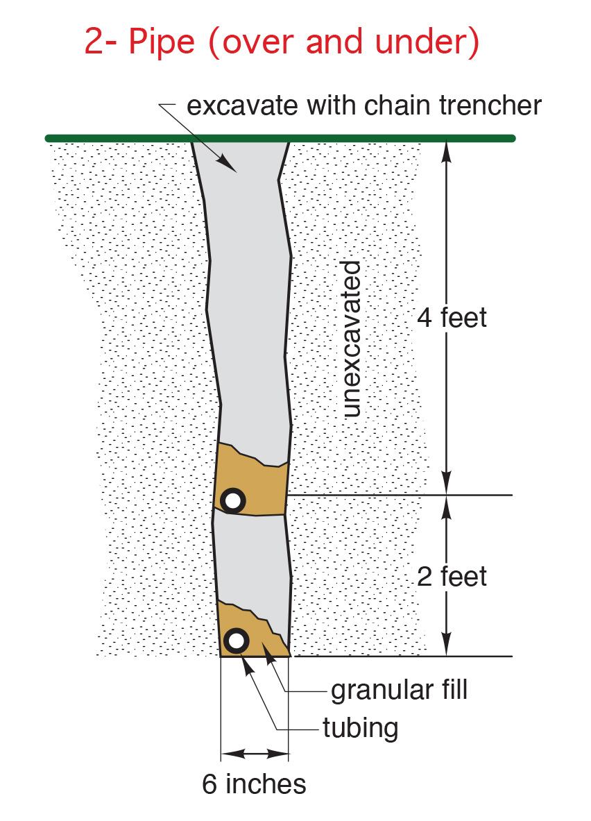
Figures 1 through 4 below show pipes installed in trenches created either by chain trenchers or backhoe-type excavators. Ground conditions typically determine which of the two are used; if the ground has soils with rocks that are no larger than fist-sized, the chain trenchers can be used. A “Ditch Witch®” is a well-known example of this type of tool. Trenches can be narrow, as shown in Figures 1 and 2, and therefore use less area for the system piping, with up to two pipes per trench. The narrow trench and its spoils will occupy less ground area before backfilling.
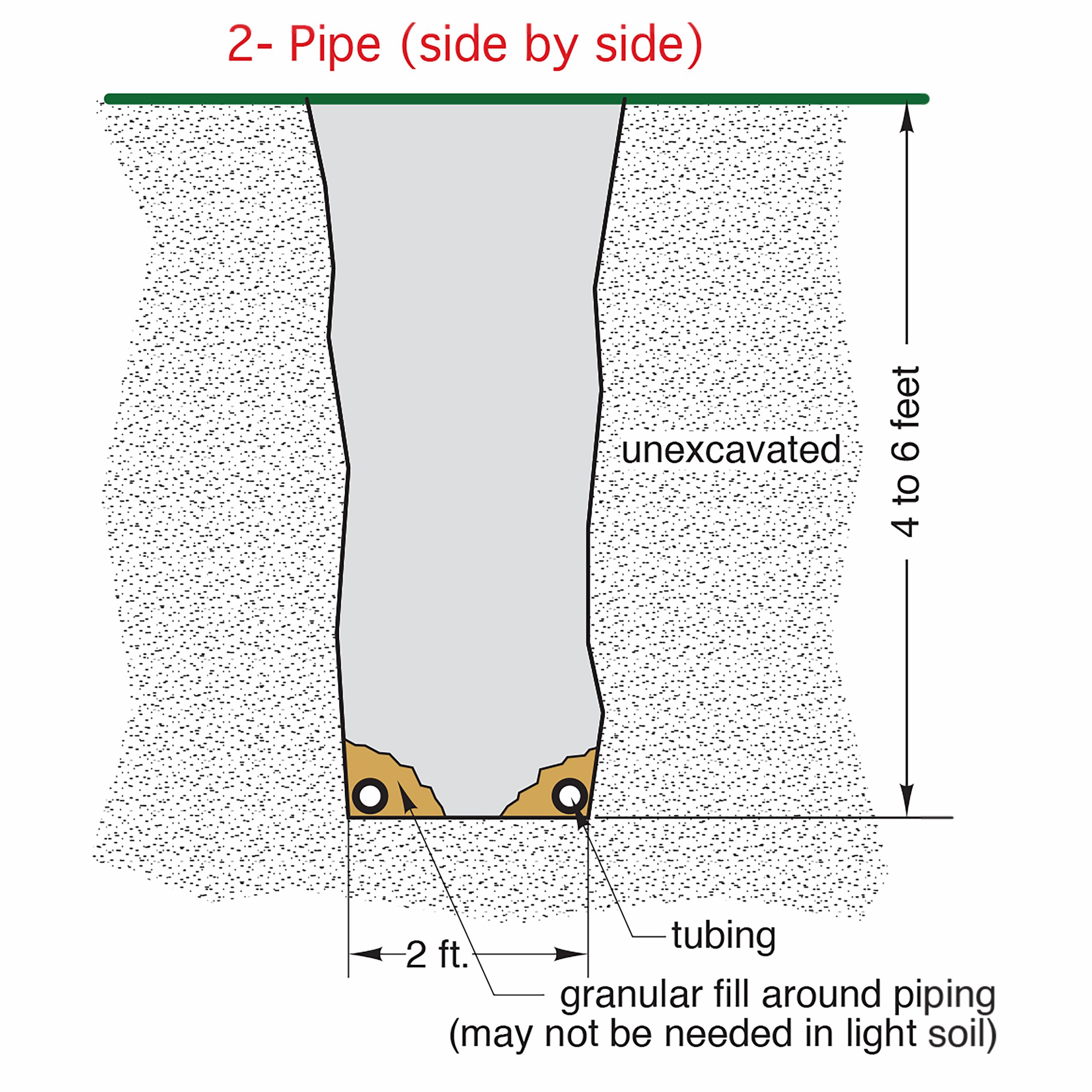
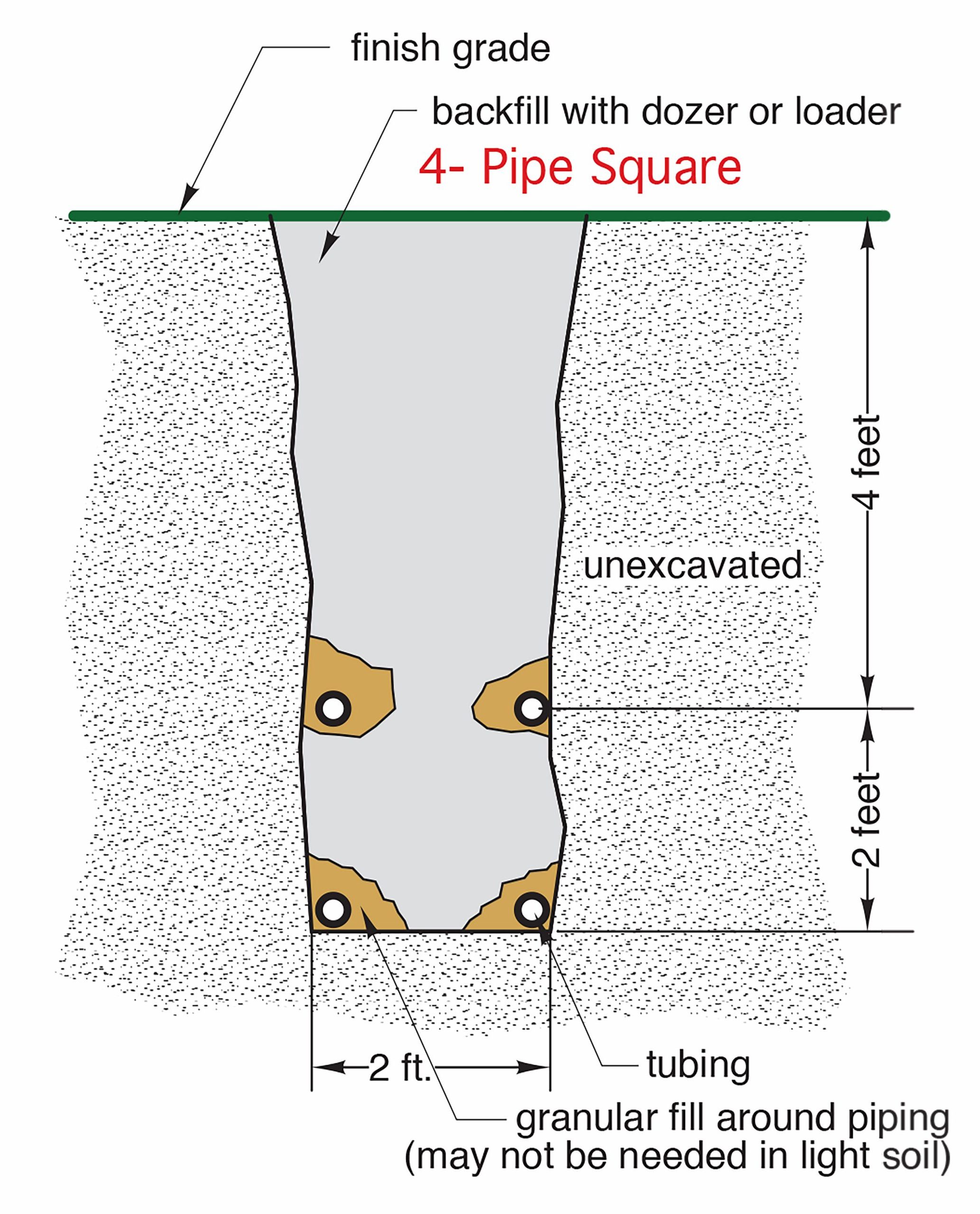
If larger excavators are needed due to soil conditions or chain trencher availability, the trenches will be wider and will therefore have room available to install two or four pipes within them, such as in Figures 21 and 22. Using four-pipe trenches can reduce the area needed for the piping “field” which may be advantageous.
Figure 5 below shows pipe fashioned into coils, known as “slinkies” and laid within wide excavated areas. These layouts work well in soils that can be excavated and back-filled using a front-end loader.
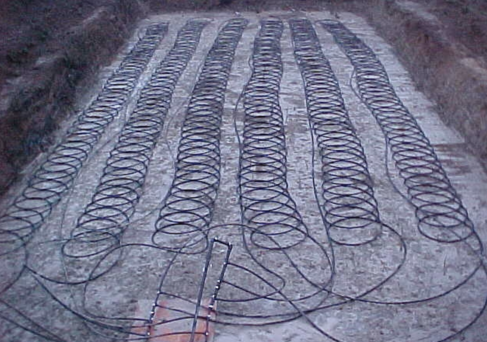
Note that the coils are attached to two manifolds seen near the bottom of the picture. This means that the coils are piped in parallel, rather than in series, with each other and reduces the power that the circulator(s) must produce in order to move the water solution through the field. Figure 6 below shows the coils partially backfilled.
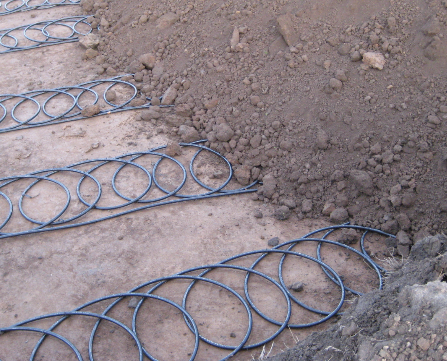
Note that in Figures 5 and 6, there is a straight run of pipe beside each coil. This is the return line from the end of the coil. There will be a supply and a return manifold for each field.
If there is insufficient area in which to install horizontal earth loops, such as in an urban neighbourhood, vertical earth loops are a viable option. Equipment that is similar or identical to that which is used by well drillers create 6-inch bore holes that can be many hundreds of feet deep. Figure 7 below shows an example of a vertical field of bore holes.
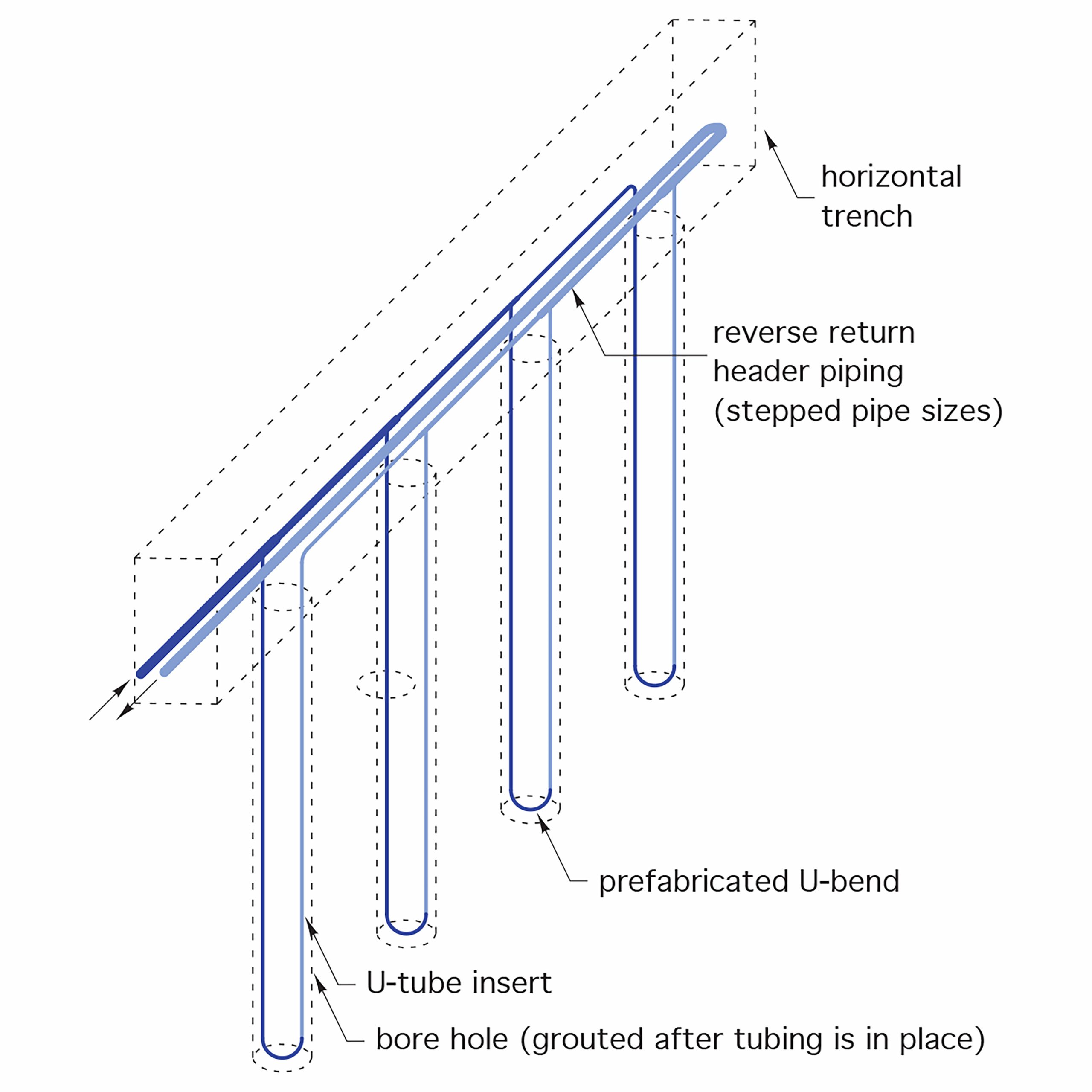
The boreholes are normally 6 inches in diameter, with 125 to 150 feet of borehole required per ton of heat pump evaporator capacity. Once a borehole is established, a U-tube of HDPE or PeX tubing is inserted down into the full depth of each borehole. Because of the tight space in the borehole, a special pre-formed return bend is fusion welded to the ends of the vertical tubes and pressure tested before being installed. After insertion, the space between the tubing and borehole is filled with a grout mixture composed of sand and an expansive clay called Bentonite. The addition of grout increases the thermal conductivity between the earth and the tubing. As well, it acts to fill the void to prevent any ground surface contaminants from making their way down into the water aquifer.
The supply and return tube from each borehole are then connected together into supply and return manifolds or “headers”, in much the same fashion as in a hydronic heating system. A reverse-return piping configuration, as shown in Figure 8 below, ensures equal flow through each borehole.
Piping for Closed Earth Loops
The most commonly used material for earth loop piping is HDPE (high density polyethylene) specifically designated as PE3608 based on the ASTM F-412 standard. This is a thermoplastic material that can be heat-fusion welded, making it very adaptable to all aspects of connecting piping for direct-earth burial. Although a DR (diameter-ratio) of 11 or lower is preferable for buried tubing, this thicker material isn’t as favourable for heat transfer as is that with a DR of higher than 11 (remember that the lower the DR number, the thicker the pipe wall). When done correctly, heat-fused joints are stronger than the base pipe itself and can last for many decades. For information regarding the processes involved in heat-fusion welding, consult the ITA modules concerned with Level 1 of the BC Pipe Trades Training programs.
Cross-linked polyethylene tubing (“PeX”) can also be used for buried earth loops, although this practice isn’t as common as is the use of non-cross-linked PE3608 tubing. PeX tubing cannot be joined by heat-fusion methods, so any buried joints must be made using mechanical means that are approved by the manufacturer. If PeX tubing is to be used, the system is carefully pre-planned so that any buried tubing is continuous and free of joints or connections, and the manifolds are accessible either inside or outside the building.
Exterior versus Interior Manifolds
A manifold is simply a series of tee connections into a main pipe, commonly referred to as a “header”. Manifolds for earth loops are most commonly formed by heat-fusing tees into a header that will increase in size according to the amount of flow through each segment, with a header at the supply and return ends of the loops. These headers are buried underground along with the loops and are not accessible for flow adjustment, temperature monitoring or for the possible addition of more loops unless they are located within a buried vault that is freeze-protected, or an aboveground structure with the same considerations. For equal flow to be an option, the loops must be connected to the mains in a reverse-return configuration, identical to that found in hydronic heating systems, and the loops must also be of the same length. If monitoring and adjustment of flow rates and temperatures is desired, or if more loops are to be added, manifolds are best installed within the building.
If the piping manifolds are outside the building, there will only be two penetrations of the foundation wall necessary; one for the supply header and one for the return header. This makes sealing of the pipe penetrations simpler. Figure 9 below illustrates a common method of sealing pipe penetrations through foundation walls.
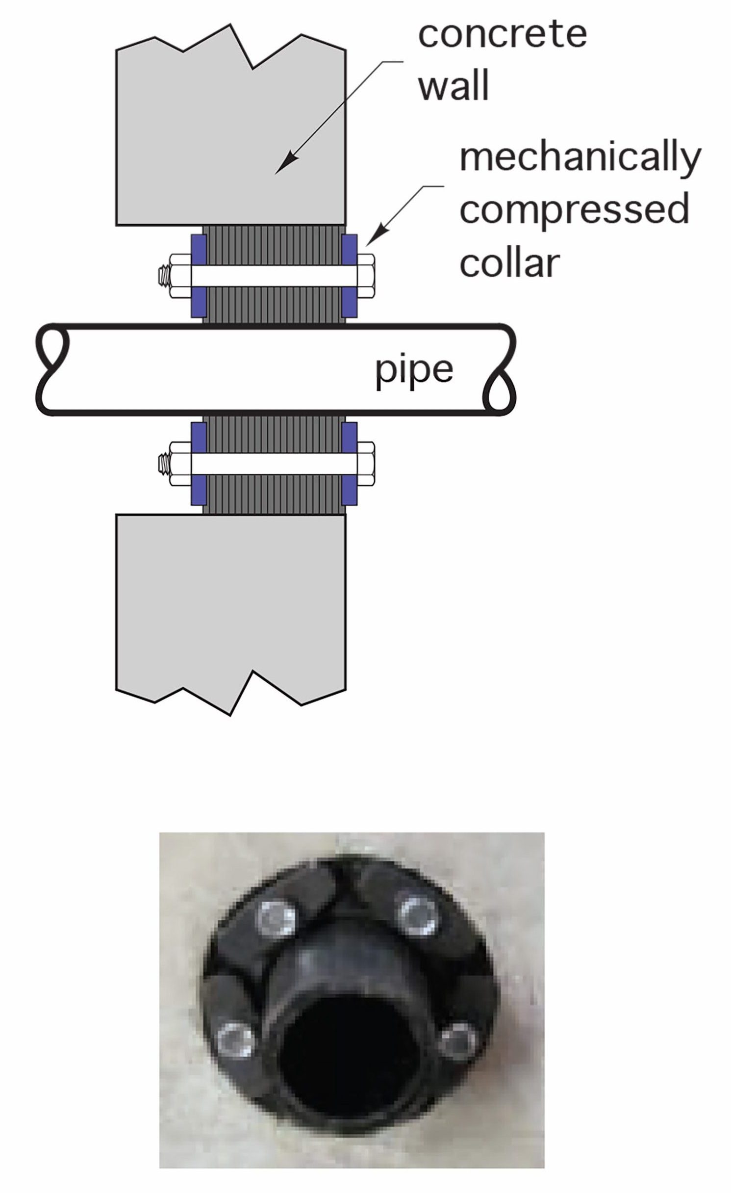
The mechanical seal shown above expands both outward and inward when compressed by tightening the through-bolts. The holes in the concrete foundation must be of a certain size in relation to the pipe and can either be pre-formed at the time of the pour or drilled through the wall using a “core drill” machine. In either case, the interior surfaces of the hole must be smooth.
The area around the pipe penetrations should be backfilled with clean granular fill and compacted adequately so as to deter soil settlement that may put stress on the pipe at the penetration.
The two obvious disadvantages of installing manifolds inside buildings are that there are many more pipe penetrations in the structure, and that the individual loop lengths must be longer. The advantages of interior manifolds are:
- reverse-return layout and equal-length loops are not necessary because of the ability to control flows and monitor temperatures for each loop from an accessible location
- “stepped” pipe size isn’t required, as the flows through each loop are now controllable
- temperature monitoring is easily accomplished by the placement of accessible thermometers
- pre-manufactured manifolds are available, which negates the necessity of heat-fused joints
- the system can be increased in capacity by the addition of more loops to the manifold
- if a leak is suspected in any loop, it can be shut down for repair without affecting the flow through the other loops
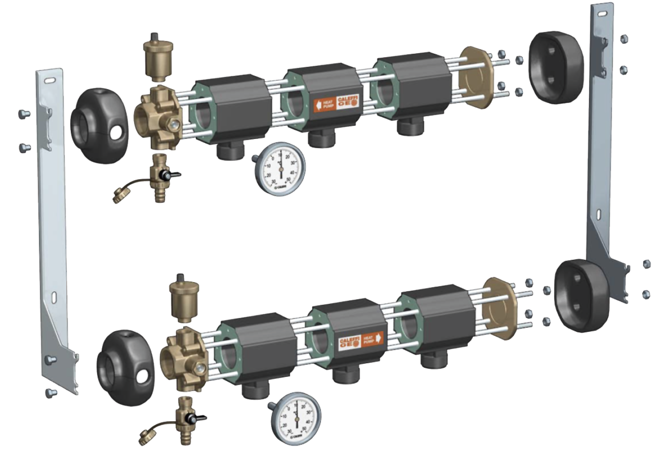
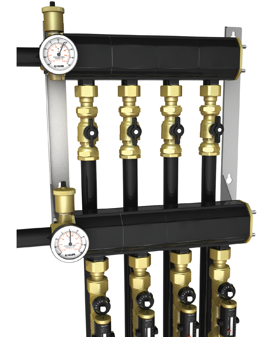
Figures 10a and 10b below shows an example of a pre-manufactured interior modular manifold.
If control of an exterior manifold is desired, they can be mounted inside a buried, semi-buried or aboveground heated enclosure, often called a “vault”. Figure 11 below is an example of a buried vault installation.
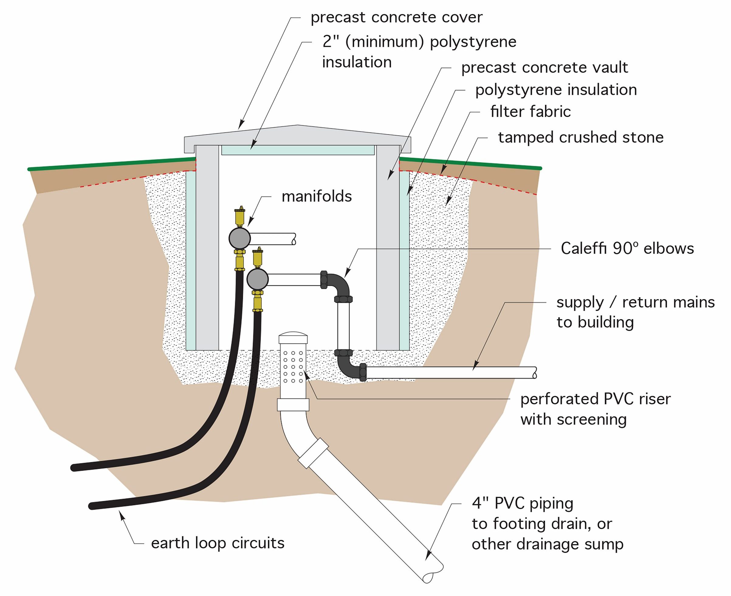
The open bottom design of the vault allows the individual loops to be routed up to their respective manifold connections, as can the manifold mains be dropped down underground to the building. As well, the open bottom prevents the vault from becoming buoyant and floating upward in the event that the ground becomes saturated. Figure 12 below shows a buried vault with a formed bottom and sealed pipe penetrations.
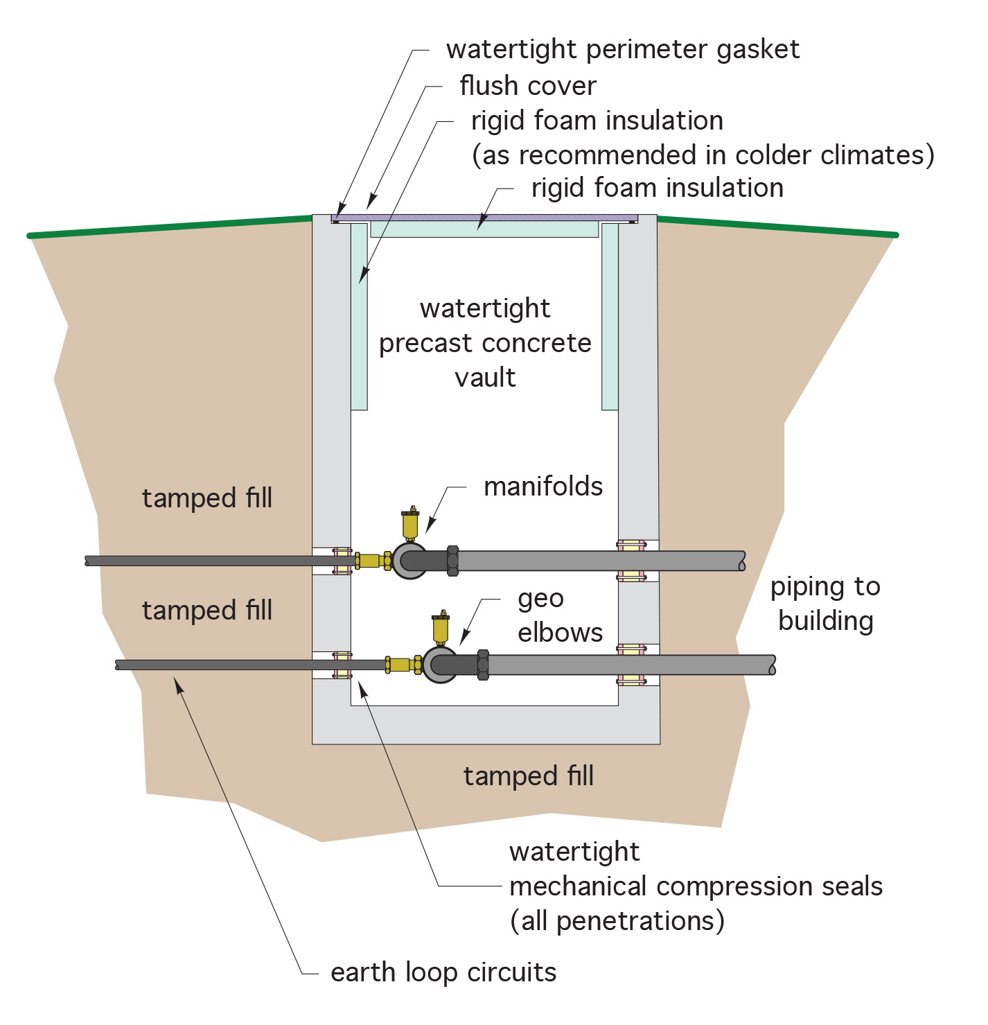
The vault in Figure 12 would be prone to “floating” in a highwater table unless engineered with extra ballast.
Earth Loop Sizing Considerations
The length of tubing required for earth loops systems depends on many factors, such as:
- the diameter and wall thickness of the tubing
- the depth of burial
- the heating and cooling capacity of the heat pump(s)
- the maximum and minimum earth loop fluid temperatures during the heating and cooling seasons
- the arrangement of the tubing within trenches or boreholes
- the thermal conductivity, moisture content, density and structure of the soil
Earth loop lengths are calculated based on the above information, for the heating load and the cooling load separately. The longer of the two lengths is then chosen. Other general considerations of note are:
- the deeper the horizontal loops are buried, the less loop length is needed
- single loops spaced further apart are more effective than multiple loops placed closer together, although less trenching may be needed. This suits an installation with minimal space available
- wet, dense soils are preferable to light, dry soils
- vertical loops will experience less soil temperature variations than will horizontal loops, and as such are more consistent with their COP over winter months
- earth loops should be designed so as to maximize turbulent flow. Turbulent flow provides more heat transfer than does laminar flow
- make sure backfill doesn’t leave any voids or air pockets, which are more insulative than conductive
- all earth loops should be pressure tested with compressed air to at least 75 psi for 24 hours, with no drops in pressure. Any leaks in underground pipe, once it is buried, will be almost impossible to pinpoint.
Connections to Heat Pumps and Equipment
An example of the piping connections and major components of an earth loop with exterior manifold and a single heat pump are shown in Figure 13 below.
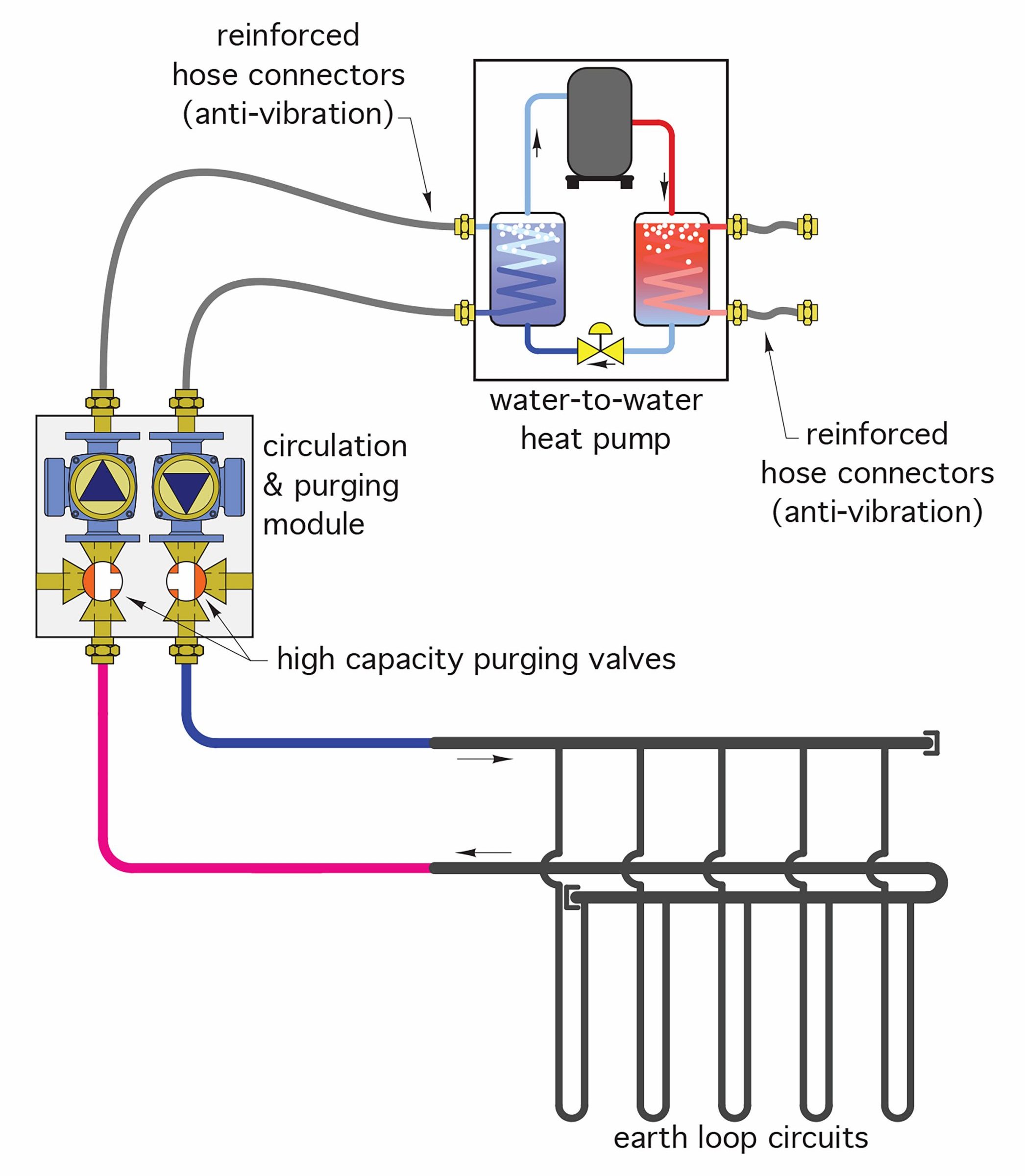
The circulation and purging module contains two circulators and two high-capacity purge valves.
The two circulators are piped in series with each other, which roughly doubles the pressure head created. This may be necessary when long loop lengths are used. The high-capacity purge valves are necessary for the filling process. When horizontal loops are used, there are many high and low points within each loop, where air can collect to cause circulation problems. Purging the loops at a high flow rate with a temporary external pump will carry any trapped air out of the loops.
Reinforced flexible hose connects the heat pump to the inlet and outlet piping. This reduces or eliminates any issues caused by vibration.
Figure 14 below shows the major components that may be found on an earth loop system using an interior manifold. Note that there are minor components that are similar to those found in a hydronic heating system. These would also be necessary for the system shown in Figure 13.
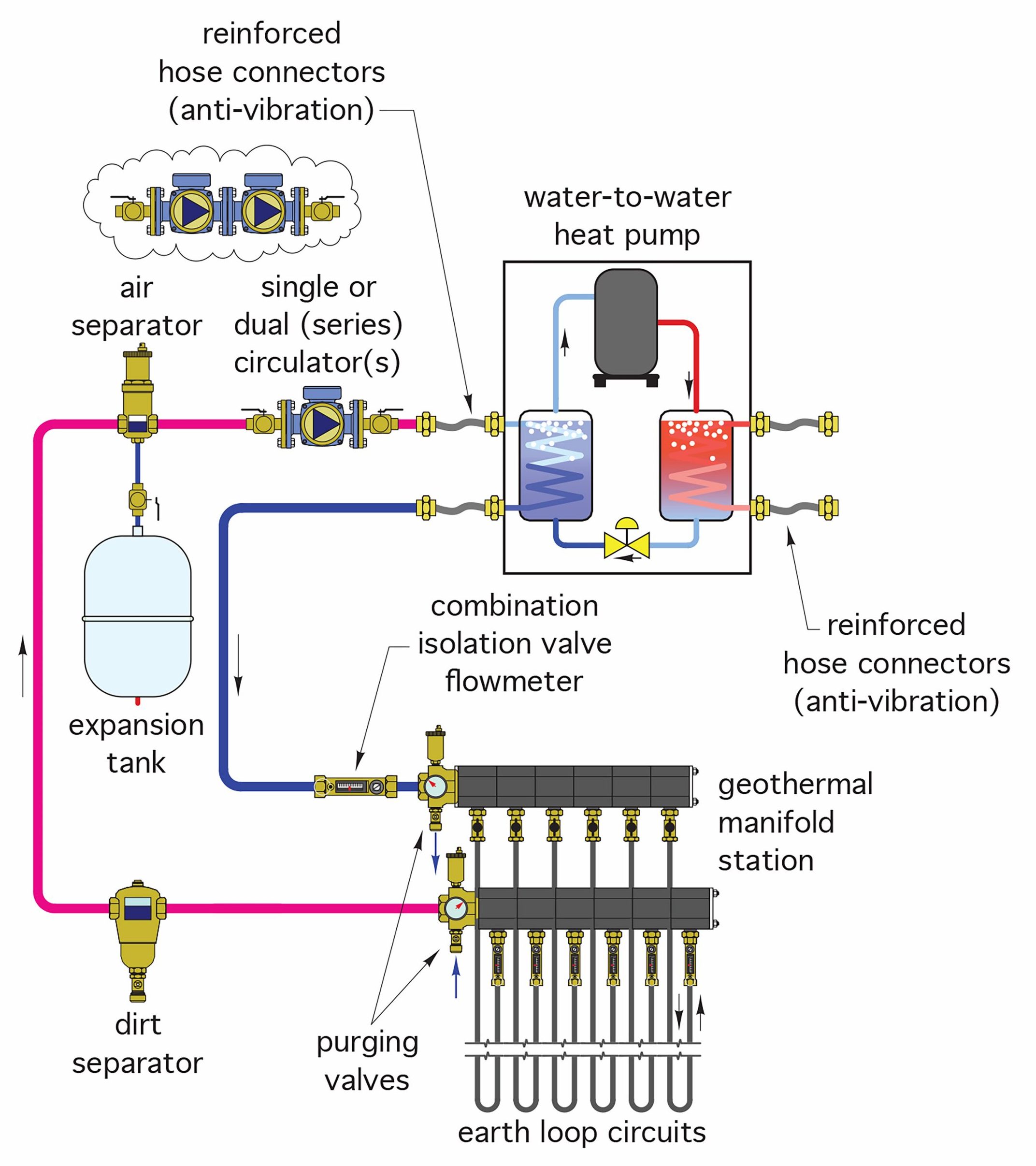
“Power-purging”, which is forcing air from the earth loops by high-velocity water flows from an exterior pump, will remove the large bubbles present during the initial filling of the loops, but because the system is “closed”, it will need to have a microbubble resorber (air separator) installed to take care of the microscopic air bubbles that will collect once the water-based solution is heated. An expansion tank is necessary to allow for the expansion and contraction of the fluid through its heating and cooling cycles. A dirt separator keeps unwanted debris from accumulating in the loops. Each individual loop can be purged of air, so the purge valves do not have to be large enough to accommodate high flow rates through the entire earth loop simultaneously.
Earth Loop Fluids
100% water is seldom used in earth loops. This is due to the fact that the refrigerant evaporators can operate at temperatures well below the freezing point of water. Thus, antifreeze solutions using salt, glycol or alcohol additives are needed.
“Brine” solutions of water and calcium chloride and potassium acetate were used in early generations of geothermal heat pump systems but, because of their corrosive nature which affected any ferrous components of the systems, they are not widely used anymore.
Alcohol-based antifreeze fluids are diluted solutions of ethanol and methanol. The negative issues with these fluids are that they are toxic and, in certain strengths, are also flammable, and therefore are banned by many jurisdictions for use in geothermal systems.
A water-based solution of food-grade propylene glycol is by far the most widely-used fluid for geothermal systems. It is non-flammable, non-corrosive and non-toxic. A common solution strength is 20% propylene glycol, 80% water. Commercial-grade propylene glycol may contain small amounts of “inhibitors” that make the solution less acidic, discourage the growth of bacteria and minimize corrosion potential.
Heat Emitters for Earth Loop Systems
As mentioned earlier, radiant floor heating systems are perfectly suited for use as the recipients of geothermal heat. They are the emitters that tend to operate at the lowest temperatures necessary to convey heat to a building. This is due to the large floor surface area available for the delivery of heat to a room. Any other heat emitter is more compact and therefore requires a higher temperature of the fluid being driven through it. Radiant floor heating system design is covered within the Hydronic Heating component of Levels 2 and 3 of British Columbia’s Plumber apprenticeship training program. An example of a geothermal system connected to a radiant floor heating system is shown in Figure 15 below.
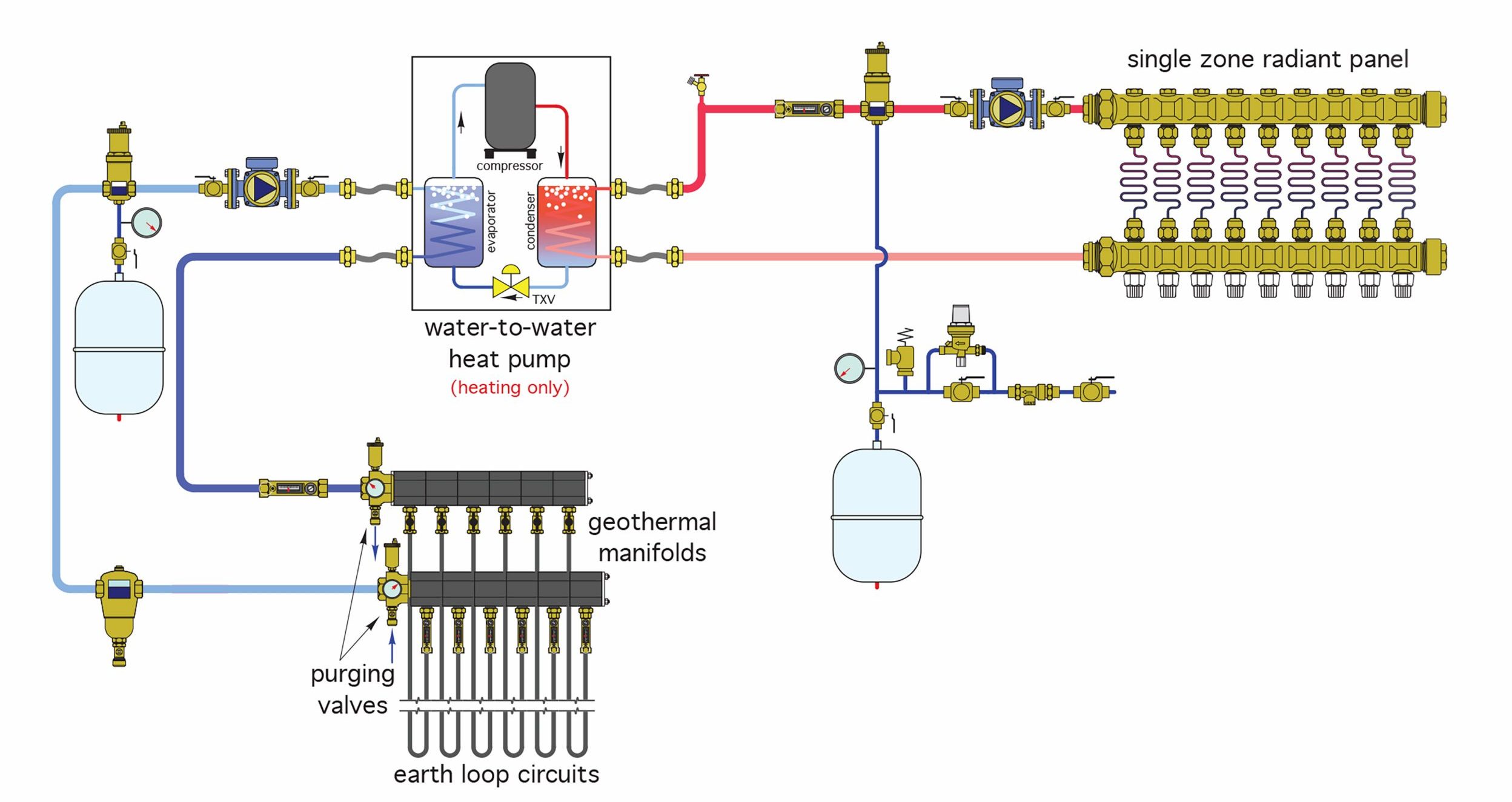
The system shown in Figure 15 is a simple single-zone heating-only application, in which the heating capacity of the heat pump is assumed to be matched to the heat output required by the floor system at the lowest design water temperature possible. The suggested maximum supply water temperature for a system such as this is 120°F (49°C). Remember that the lower the supply water temperature required, the higher the heating capacity and COP of the heat pump. With a single zone application and a heat pump output matched to the design heat loss, the system would simply be turned on and off whenever there is a call for heat.
On larger heating-only systems with multiple zones, where the heat pump’s output is designed for all zones possibly needing heat at the same time, the installation of a buffer tank is necessary in order to prevent the heat pump from short cycling. Figure 16 below shows such an arrangement.
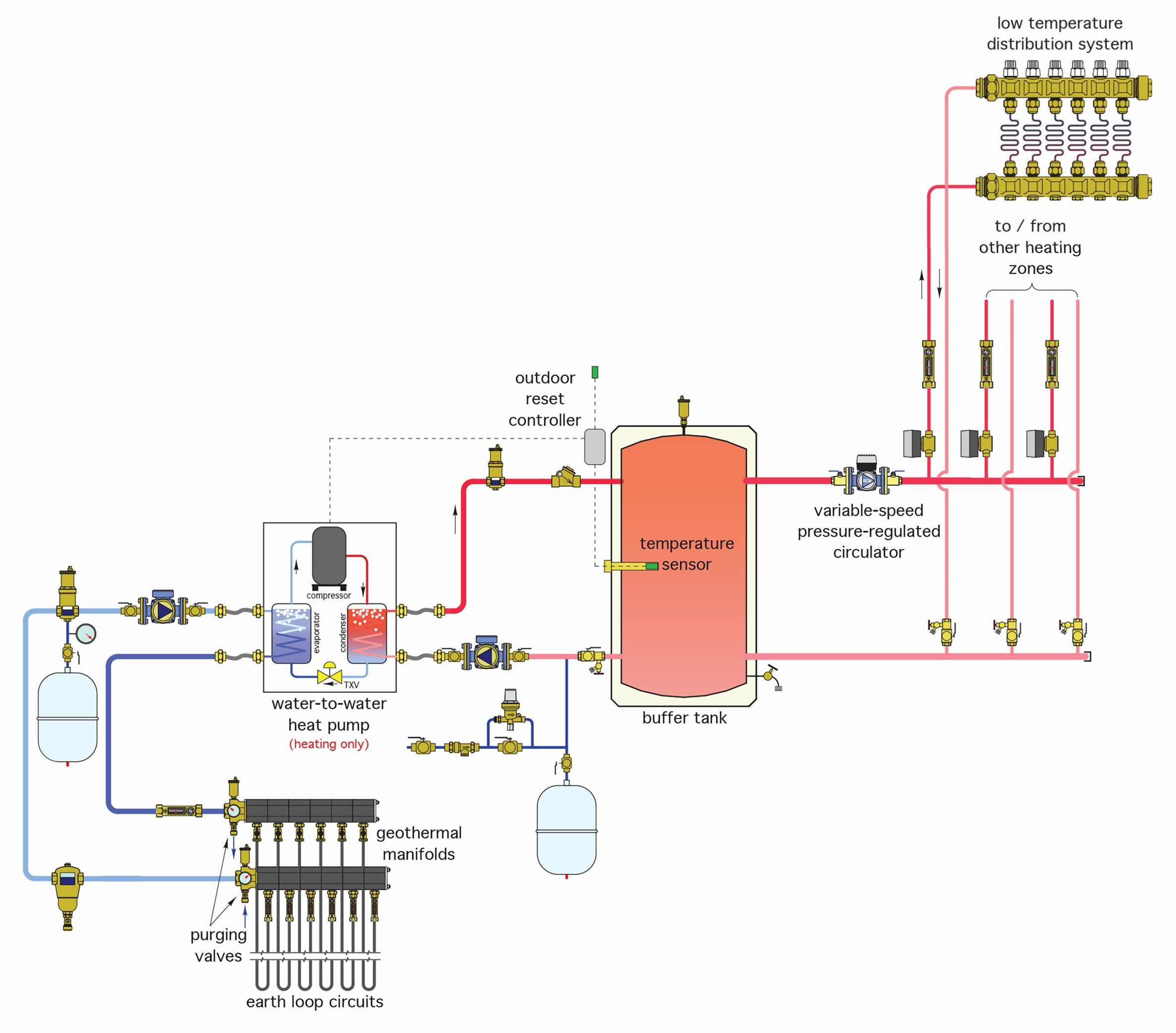
The buffer tank is the “load” for the heat from the geothermal system and in turn is the heat “source” for the radiant floors. An outdoor reset control is used to maintain the temperature of water in the buffer tank as calculated by the needs of the floor system. In this way, there is no mixing valves needed for the floor system. The large thermal mass of the buffer tank allows the heat pump to operate for longer periods of time and thereby reduces the possibility of short-cycling. As well, it acts as a hydraulic separator between the load side of the heat pump and the radiant floor circulators.
Figure 17 below shows an example of multiple heat pumps being used to supply heating-only to a radiant floor system with multiple zones. An outdoor reset control will operate to cycle the heat pumps on and off as needed to maintain the required temperature in the buffer tank.
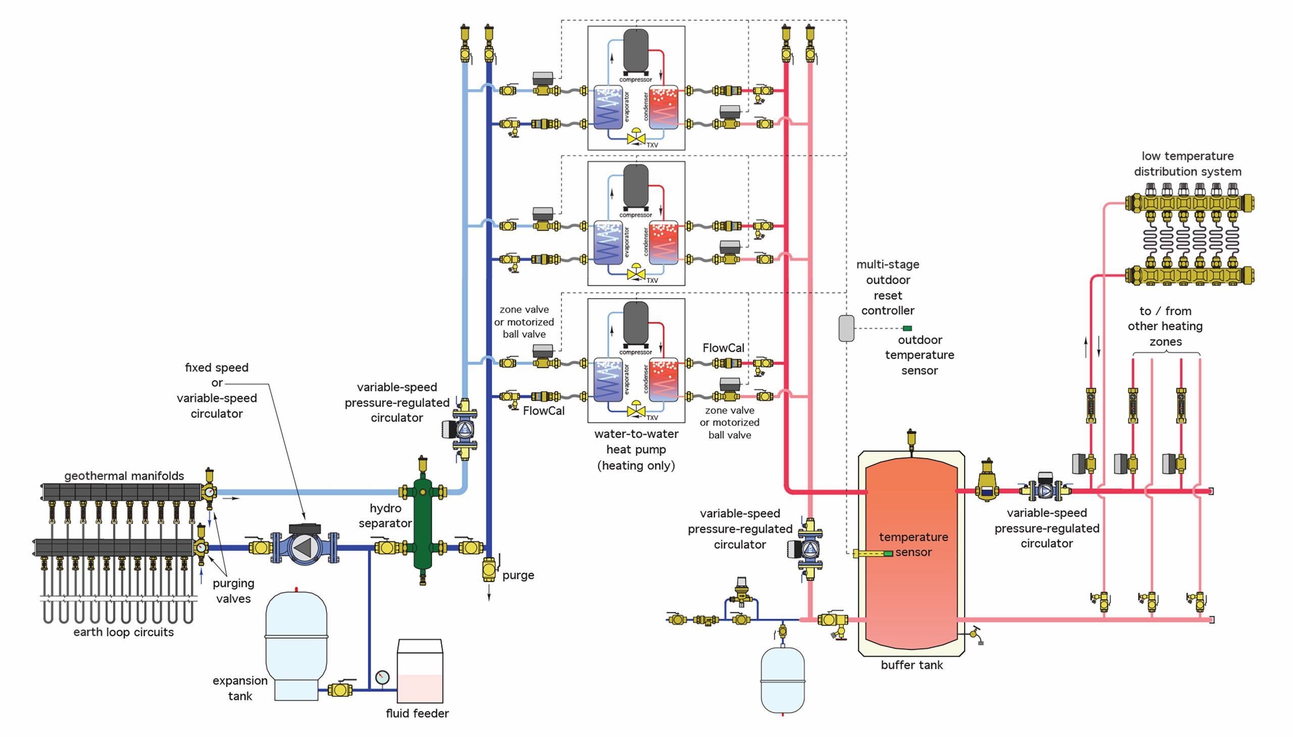
This control strategy is similar to that used by multiple boilers. The trend for many decades now has been to use a number of small heating plants, rather than one large one, to supply the heat demand. This achieves greater efficiencies in the shoulder seasons where the heat needed is minimal.
Now complete Self-Test 3 and check your answers.
Self-Test 3
Self-Test 3
- If a chain trencher is used, how many pipes can be buried in the trench?
- 1 only
- 1 or 2
- 1 to 3
- 2 to 4
- What is the normal capacity of a 6-inch vertical borehole in feet per ton of capacity?
- 75 – 100
- 100 – 125
- 125 – 150
- 200 – 250
- What is used in a borehole to increase the thermal conductivity between the tubing and the earth around it?
- Nothing
- Concrete
- Gypsum and gravel
- Sand and Bentonite
- How are the manifolds piped in a vertical field?
- In a series-loop configuration
- In a Monoflo® tee configuration
- In a reverse-return configuration
- In any configuration that uses less pipe
- What is the material that is most commonly used for earth-loop piping?
- PeX
- PVC
- CPVC
- HDPE
- How is earth-loop piping joined?
- Using crimped connections
- Using heat-fusion methods
- Using threaded connections
- Using pressed fittings and methods
- If manifolds are installed inside a building, how many wall penetrations will there be?
- None
- Two only
- Four or more
- Two for each field loop
- Which one of the following choices would not be an advantage to installing manifolds within the building?
- There are many pipe penetrations through foundation walls
- Flow through each loop can be monitored and adjusted
- Length of larger-diameter manifold pipe is reduced
- Temperature of each loop can be monitored
- Which one of the following choices would not be an advantage to installing vertical, rather than horizontal, earth loops?
- There is less ground area needed
- There is less soil temperature variation
- Specialized well-drilling equipment and personnel is needed
- More vertical pipe means less chances of air pockets being formed
- What is the accepted pressure and duration of the air test on all buried piping in earth-loop installations?
- 15 psi for 1 hour
- 50 psi for 2 hours
- 75 psi for 24 hours
- 150 psi for 72 hours
- What is “power-purging”?
- Freeze-protecting loops using electrolysis
- Heat-fusing HDPE using high-temperature air
- Adding antifreeze by using pressurized water
- Removing trapped air by using high-velocity water flows
- What type of antifreeze solution was used in early versions of geothermal heat pump field loops but is no longer the industry standard?
- Alcohol-based
- Ethylene glycol-based
- Calcium chloride-based
- Propylene glycol-based
- What type of heating system is best suited for use with geothermal heat pumps?
- Forced air
- Radiant floor
- Cast-iron radiator
- Baseboard wallfin
- The installation of what piece of equipment helps ensure that a heat pump in a multiple-zone heating system doesn’t short-cycle when only one or two zones are calling for heat?
- A buffer tank
- A heat exchanger
- An expansion tank
- A water makeup line
- What control component is used to maintain the temperature of the water in a buffer tank, and thereby eliminate the need for a mixing valve?
- A thermostat
- An expansion tank
- An outdoor reset controller
- A differential pressure relief valve
Check your answers using the Self-Test Answer Keys in Appendix 1.
Media Attributions
- Figure 1 Single pipe in trench © Caleffi Hydronic Solutions. Used with permission.
- Figure 2 Two pipes vertically in trench © Caleffi Hydronic Solutions. Used with permission.
- Figure 3 Two pipes horizontally in trench © Caleffi Hydronic Solutions. Used with permission.
- Figure 4 Four pipes in trench © Caleffi Hydronic Solutions. Used with permission.
- Figure 5 “Slinkies” laid into large-area excavation © Caleffi Hydronic Solutions. Used with permission.
- Figure 6 Partially backfilled “slinkies” © Caleffi Hydronic Solutions. Used with permission.
- Figure 7 Field of boreholes with vertical loops © Caleffi Hydronic Solutions. Used with permission.
- Figure 8 Reverse-return manifold piping © Caleffi Hydronic Solutions. Used with permission.
- Figure 9 Mechanical seal for pipe penetrating a foundation wall © Caleffi Hydronic Solutions. Used with permission.
- Figure 10a Exploded view of modular geothermal manifold © Caleffi Hydronic Solutions. Used with permission.
- Figure 10b Assembled view of modular geothermal manifold © Caleffi Hydronic Solutions. Used with permission.
- Figure 11 Exterior manifold in a buried vault © Caleffi Hydronic Solutions. Used with permission.
- Figure 12 Watertight buried vault © Caleffi Hydronic Solutions. Used with permission.
- Figure 13 Piping connections between the earth loops and heat pump © Caleffi Hydronic Solutions. Used with permission.
- Figure 14 Piping connections and components of a heat pump and interior manifold © Caleffi Hydronic Solutions. Used with permission.
- Figure 15 A single-zone, combination geothermal radiant heating system © Caleffi Hydronic Solutions. Used with permission.
- Figure 16 Geothermal/heating only system using a buffer tank © Caleffi Hydronic Solutions. Used with permission.
- Figure 17 Multiple heat pumps supplying a multi-zone heating-only radiant system © Caleffi Hydronic Solutions. Used with permission.
