Learning Task 2
Active Solar Thermal System Operation
There are many different ways to combine solar thermal collectors with system hardware to provide options for space heating as well as for domestic hot water. In some cases, both loads can be supplied from a single system. Figure 1 below shows probably the simplest active solar thermal system.
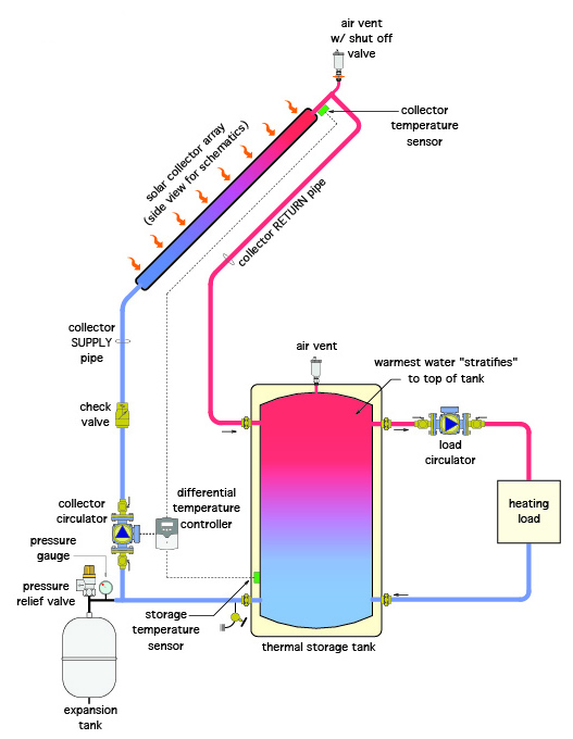
This system consists of one or more collectors, circulators, an expansion tank, a storage tank, a heat load, control components and the piping connecting them. This is how it operates.
The collector temperature sensor and storage tank temperature sensor are connected to the differential temperature controller. This controller constantly measures the difference between the two sensors, and when the water temperature at the collector exceeds the tank water’s temperature by from 3 to 10°F, the differential controller starts the pump which moves the cooler water from the bottom of the tank up through the collector array and back to the tank. When the collector temperature is very close to, equal to or below the tank’s temperature, the differential controller shuts the circulator off. Some differential controllers contain logic that can adjust the speed of an ECM circulator to more fully utilize the heat gained by the collector, speeding it up when there is much heat to be harvested or slowing it when, for instance, clouds pass over. The check valve installed in the collector supply piping ensures that, if the temperature of the collector water is lower than that of the storage tank water, thermosiphoning won’t occur. Thermosiphoning would eject the tank’s heat back out to the atmosphere through the collector if the circulator stops and the collector’s temperature was below that of the tank. The load on the system, shown to the right of the storage tank, has its own circulator and would draw heated water from the storage tank whenever the demand for heat at the load is there.
The downsides to this simple system are:
- It doesn’t have any means of freeze protection, and
- There is no alternate or “backup” source of heat for the load if the water in the storage tank cools overnight
This simple system needs further controls and equipment to adequately address these shortcomings, and to also provide for various different configurations caused by other added loads.
Methods of Freeze Protection
Firstly, any active solar system installed in North America should have a method of freeze protection that will work automatically. Even states such as Florida and Texas can experience freezing temperatures that would damage the system, even if it were to only occur overnight. Obviously, any system installed in Canada must have freeze protection as a necessary option.
One option for freeze protection is to use antifreeze in the piping between the collector and storage tank. This is known as a closed-loop antifreeze system and is shown in Figure 2 below.
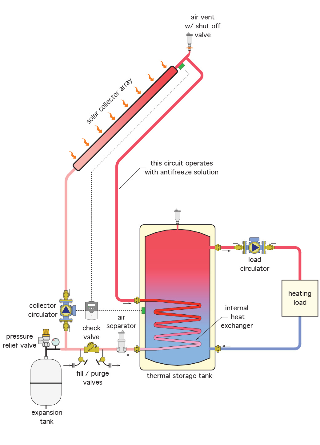
In this system, the storage tank is actually a heat exchanger. The coil within the tank keeps the antifreeze solution separate from the heat load fluid, negating the need for antifreeze within the heat load’s system. The tank and system load piping would need to be located within a heated space.
Figure 3 shows a heat exchanger mounted external to the tank, rather than within it. Although it contains antifreeze on the collector side, the heat exchanger would have to be mounted within a heated space to prevent the system water side from freezing.
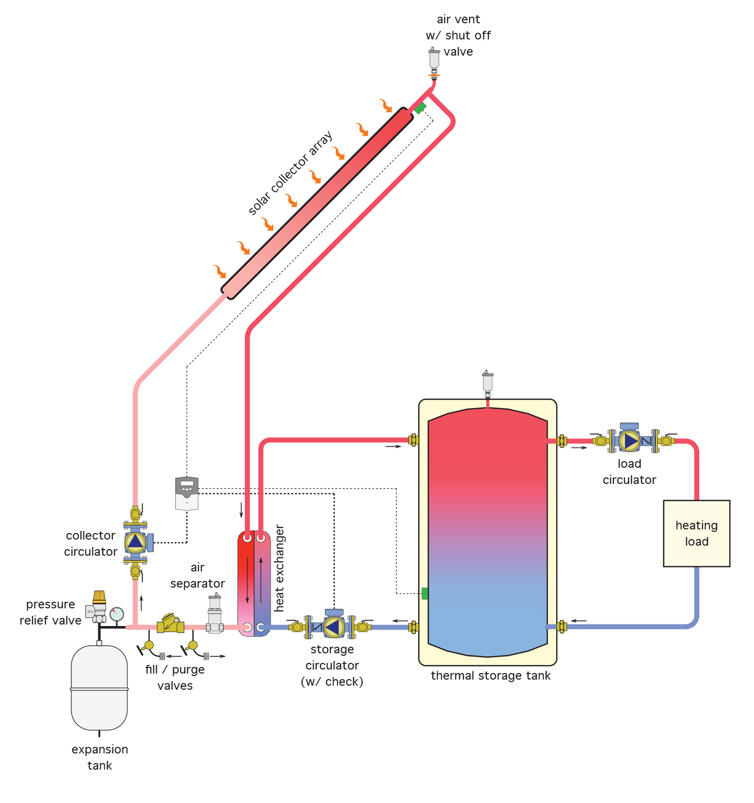
Systems having storage tanks with internal coils only need one collector circulator, whereas two are needed when using an external heat exchanger, which results in added costs for the circulator and the total power consumption. In either case, the heat exchangers should be generously sized to maximize system efficiency. The larger the heat exchanger, the cooler the collector array can operate relative to the storage tank temperature. As previously mentioned, the cooler the collector operates, the higher its efficiency.
An alternative method of freeze protection is to drain the water from the collector array and any other exposed piping whenever there is no collection of solar energy during freezing ambient temperatures. This option is called a drainback system. It relies on properly graded piping to quickly empty the collectors and associated equipment.
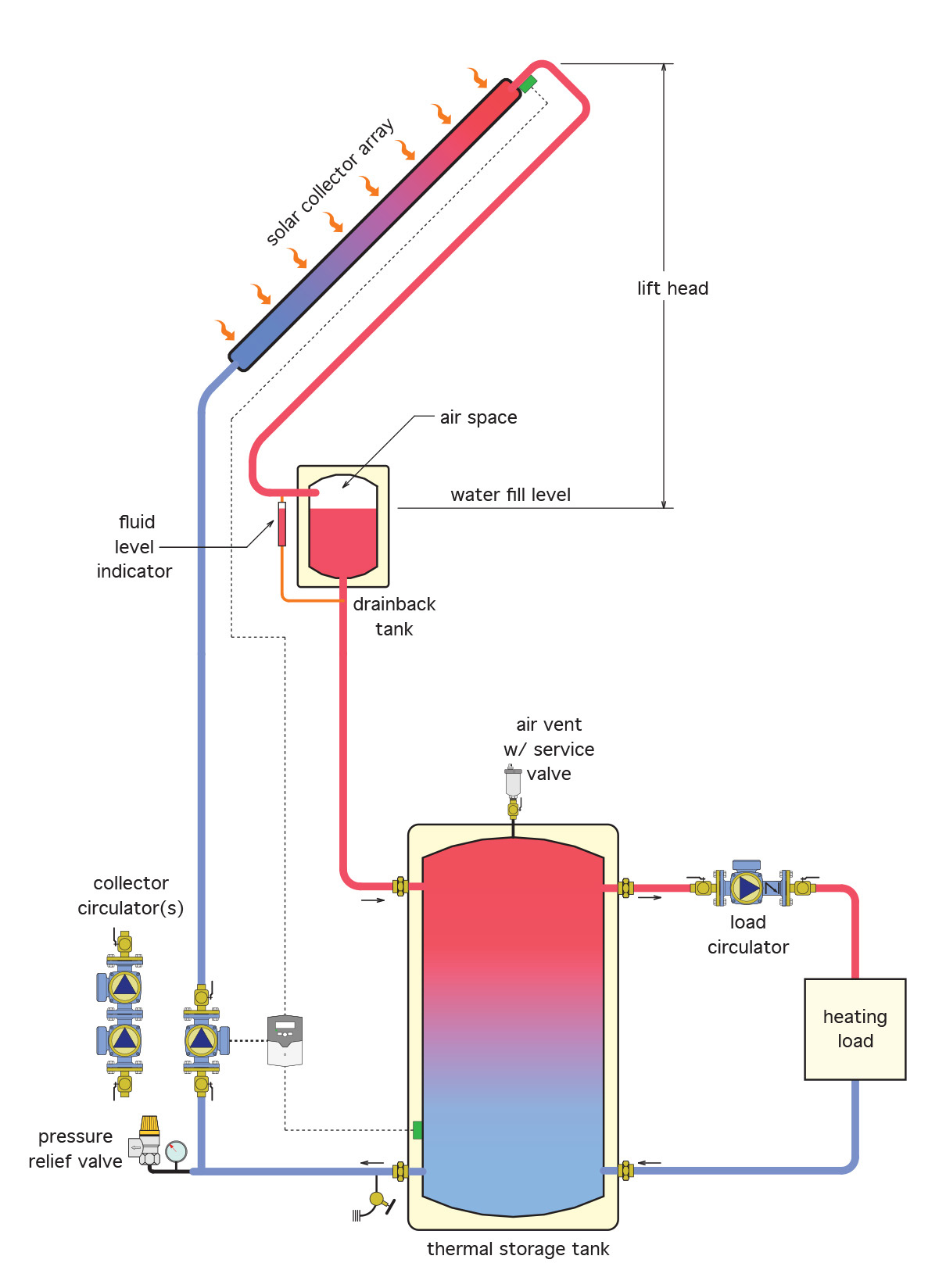
The thermal storage tank, drainback tank and circulators are all installed within the boiler room or other heated space. The drainback tank is installed in as high a location as possible, in order to minimize the length of piping that is exposed to freezing conditions. The system is filled so that the water level is somewhere within the bottom half of the drainback tank. A fluid level indicator, such as a sight glass, is mounted parallel to the tank to give a visual indication of the water level within the tank. There should be enough air space left in the tank to accommodate the water contained within the collector array and exposed piping. Accordingly, the tank should be carefully sized. When the differential controller senses more heat at the collector than at the tank, the circulator starts and fills the collectors and piping. The water from the collector array spills into the drainback tank through the collector return. When the circulator shuts off due to little or no temperature differential, water will fall back through both the collector supply and return piping to the air space within the drainback tank, thus emptying any portion of the system that could freeze. It is important that there not be a check valve in the collector supply piping. This would prevent the exposed portion of that pipe from draining and would thus freeze. One downside to a drainback system is that, even though it is a closed system, the collector circulator has to be strong enough to “lift” water from the level of the drainback tank to the top of the collectors. In some cases, two circulators installed in series are necessary to create enough head to get this job done. Once the water spills through the collectors and into the return, it creates a siphon which assists the collector circulator so that less power is consumed. A bonus to this system is that the drainback tank, if properly sized, can also act as the expansion tank for the system water. Also, there is no automatic air vent at the top of the system collectors. Any air within the system is directed to the drainback tank where it adds to the space needed for the water to settle into in the “off” cycle.
Both types of freeze protection have advantages and disadvantages.
Closed-loop antifreeze advantages:
- Pitched piping not required
- Low wattage circulators can be used
- No drainback tank needed
Closed-loop antifreeze disadvantages:
- Extra expense of heat exchangers, antifreeze, expansion tank, pressure relief valve and purge valve
- Extra monitoring for pH level
- Increased awareness needed for cross connections and backflow prevention
Advantages of closed-loop drainback systems:
- Slightly higher efficiencies by operating collectors at lower temperatures
- No antifreeze and associated equipment needed
- Drainback tank can also act as an expansion tank for rest of system
Disadvantages of closed-loop drainback system:
- Piping and collectors not pitched properly can cause much damage if freeze-up occurs
- Higher pumping power required due to head difference
- Proper drainback tank liquid level must be maintained
- Drainback tank must be located as high as possible in a heated space
- Extra expense of drainback tank and possibly extra pump
As you can see, there are many considerations that will factor into the choice of a freeze protection option.
Active Solar Domestic Water Heating
Some of the most economically viable active solar thermal systems are those used for the heating of domestic hot water. These can be as small as a system found in a rural cabin or can be large enough to supply hot water demands for a hotel, laundromat or commercial office building. Let’s look at some of the options available.
A single-tank system is shown in Figure 16 below. This system uses a storage tank with an internal electric heating element and heat exchanger.
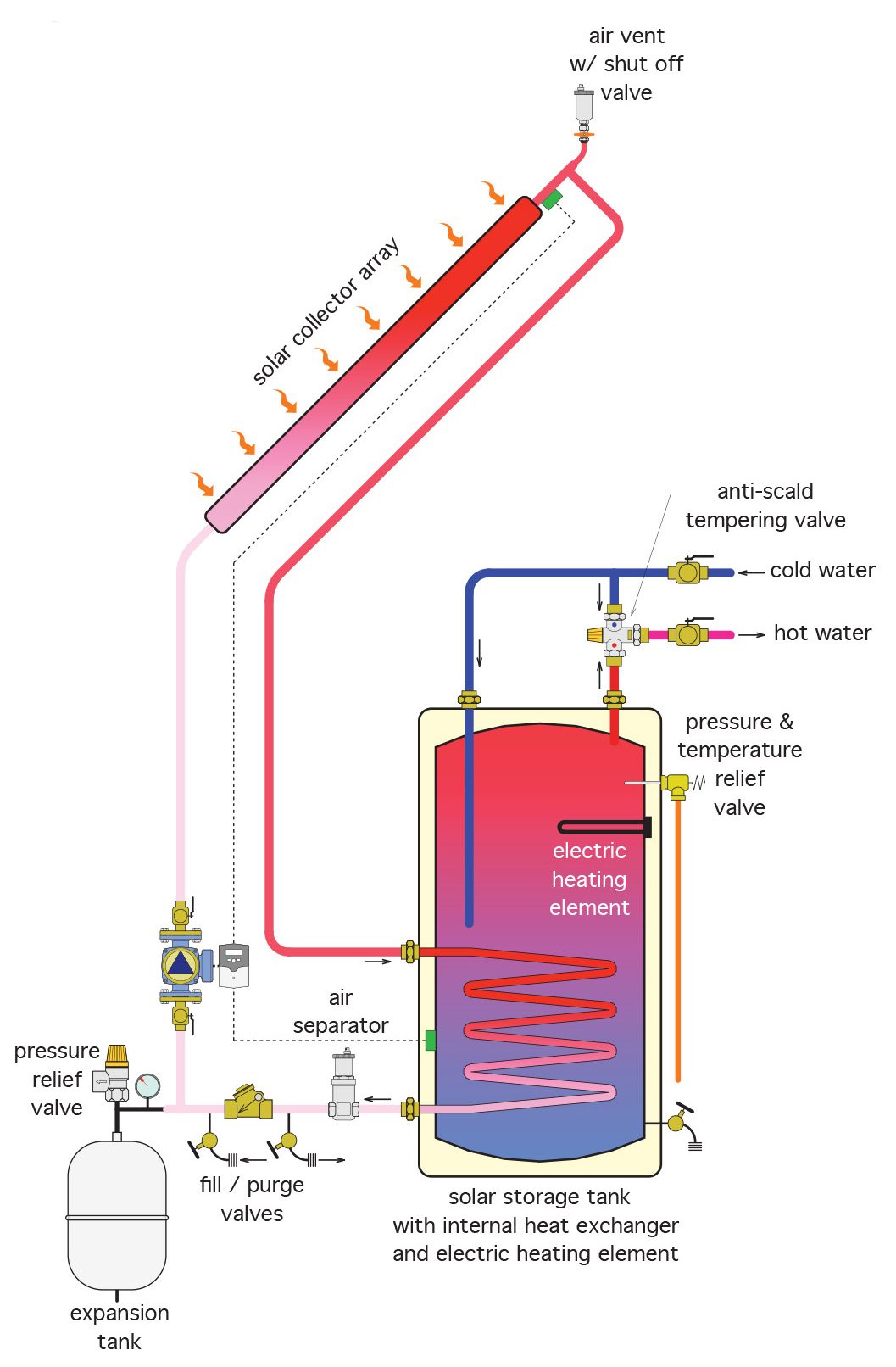
In this system, an internal coil provides solar heat (or pre-heat) for the domestic water surrounding the coil. A thermostatically-controlled electric immersion element near the top of the tank cycles on and off to keep the water temperature in the top of the tank at its desired setpoint, usually 140°F (60°C). A tempering (“anti-scald”) valve at the tank outlet adds cold water to excessively-hot water leaving the tank so that scalding water is not delivered to any faucets. This is a critical component of the system. In times of high sunlight and low usage, collector water can get extremely hot, and water temperature being supplied to any hot water faucet should not exceed 120°F (49°C).
As hot water is drawn off the top of the tank, incoming cold water replaces it and is directed to the bottom of the tank through an internal dip tube. Temperature stratification (layering) of water in the tank ensures that the hottest water for the faucets is drawn from the top of the tank while the coolest water at the bottom is pulled out to the collectors by the circulator. Remember that cooler water fed into the collectors ensures the best collector efficiency.
To avoid damage from possible stagnation, the isolation valve at the high point vent should be closed once the system is filled. It can be opened again if the system is ever drained and refilled.
Alternatively, as described earlier, an external heat exchanger can be used with a single-tank system. In Figure 6 below, note that there are two circulators needed, along with an expansion tank on the collector side of the heat exchanger. The collector loop is a closed-loop glycol-based circuit and would therefore operate in the same manner as a hydronic heating system, requiring makeup water components, an expansion tank and circulator as well as control components.
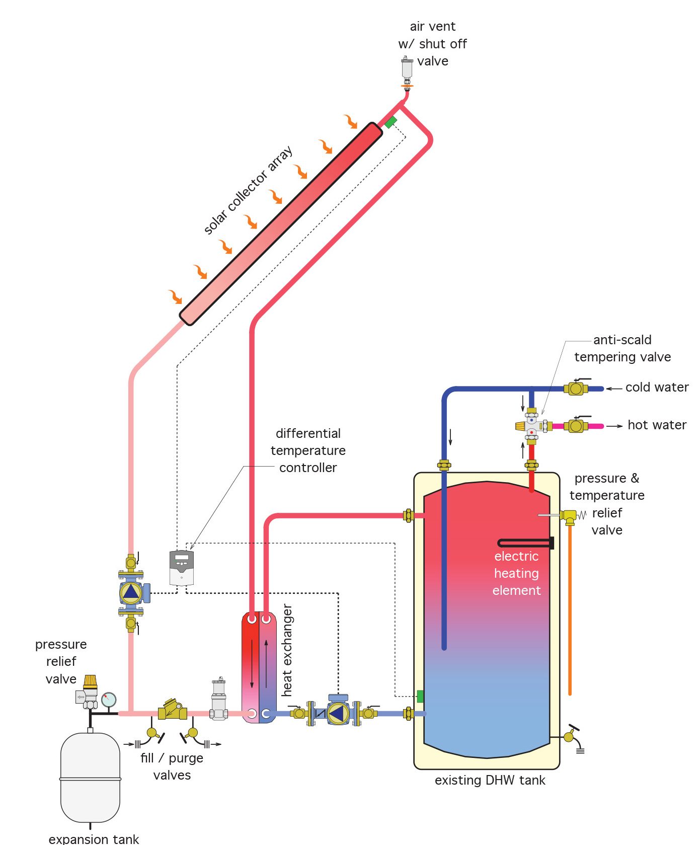
When the differential temperature controller senses enough heat differential between the collector and DHW tank, both circulators start, and heated glycol-based water is circulated through one side of the heat exchanger. Potable water is simultaneously circulated through the other side of the heat exchanger in a counterflow pattern. As in the previous example, the tank’s electric immersion element will operate automatically and independently of the solar system to try to maintain 140°F (60°C) water at the top of the tank. An anti-scald valve near the tank’s hot water outlet will ensure that excessively hot water leaving the tank is cooled to satisfy code requirements.
Existing single domestic hot water tanks can be retrofitted to accommodate solar energy collection, and their small footprint makes them advantageous over a multi-tank set-up. However, they don’t typically collect as much solar energy on an annual basis as systems that separate the solar storage tank from the auxiliary heat source (electric immersion-type or gas-fired).
Two-Tank Systems
Increased storage mass and the separation of the conventional energy source contribute are the main reasons for two-tank systems providing greater solar energy collection on an annual basis as compared to single-tank systems. These are typical installations for existing residential DHW systems, providing there is enough space for the extra tank. As seen in Figure 18 below, in a two-tank system, cold water enters the bottom of the solar storage tank through a dip tube, and leaves the tank through the outlet at the top, where it feeds into the cold water inlet of the existing conventional tank. If there is enough solar energy to collect, the solar system may provide all the heat necessary for DHW supply. If the solar capacity is reduced at all, the conventional system adds heat as needed. Remember that even a slight pre-heating of the water going into the conventional tank can result in a substantial energy cost saving. For example, water heated from 50°F (10°C) to 90°F (32°C) represents about 40/90 or 44% of the energy input needed to raise that water to a final temperature of 140°F (60°C). This can result in a substantial reduction of energy costs on an annual basis.
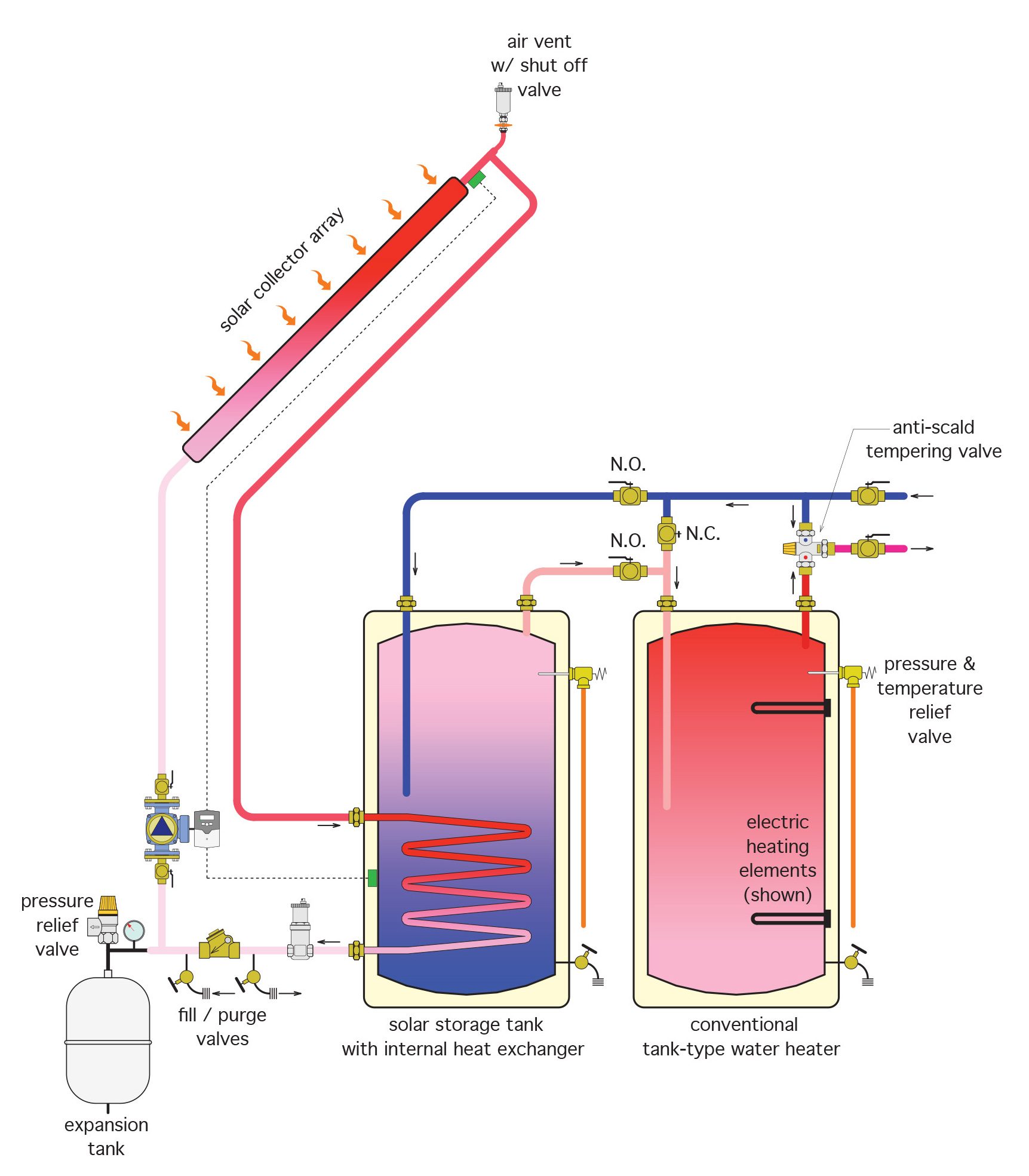
Tees and valves are installed so that either tank can operate if the other one needs to be shut down for maintenance, repair or replacement. The solar side of the single and two-tank systems operates typically, with the differential temperature controller operating the circulator whenever there is heat to be gained. Although not shown in Figure 7, a check valve should be installed to prevent off-cycle losses through thermosiphoning.
Bypass Systems
Figure 8 shows a system that can be used in conjunction with a modulating tankless water heater. This system has the two heaters piped in parallel, with a diverting valve controlling the path of the heated water out to the domestic potable system.
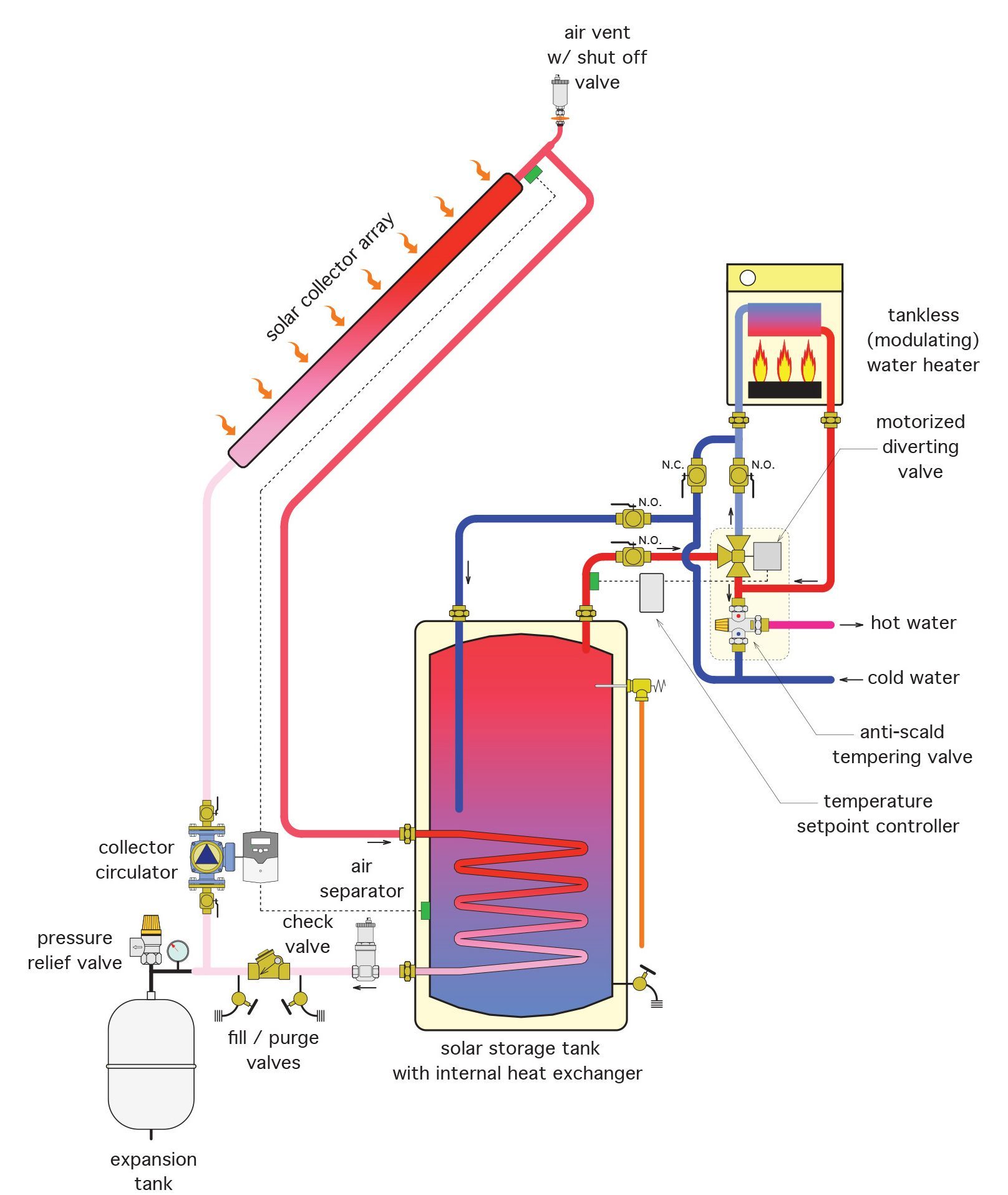
The solar side of the system is as in the single tank system, with a glycol-water mixture being circulated through an internal coil in the tank. On the domestic potable side, the temperature of the water leaving the storage tank is constantly monitored. If the water is hot enough to go directly to the faucets, the motorized diverter valve routes it to the anti-scald (tempering) valve and out to the faucets. If the water leaving the tank needs additional heating, the diverter valve routes it to the tankless heater. From there it again passes through the tempering valve on its way to faucets. Just as in the two-tank system, tees and isolating valves are installed to allow, in this case, the tankless heater to operate as the sole supplier of heated water in the event that the solar tank is out of service for any reason.
One of the benefits of this system is that the tankless heater doesn’t add any heat to the solar storage tank and thereby allows the solar collectors to operate at as low an inlet temperature as possible. This ensures maximum efficiency of the collector array. Another benefit is that the system doesn’t have the additional surfaced area of a second tank, so standby heat losses are minimized. Thirdly, the wall-mounted tankless heater takes up less of a “footprint” in the mechanical room relative to that of a two-tank system.
Solar Circulation “Stations”
Just like hydronic heating equipment manufacturers, many producers of solar heating equipment recognize the advantages of assembling the necessary solar components into a pre-packaged unit called a “station”. Figure 9 below illustrates that concept.
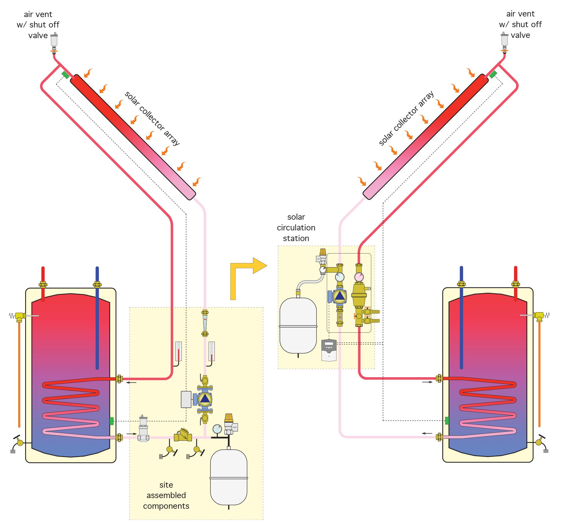
In the figure above, the diagram on the left shows the equipment that would be installed separately in the solar collector side of a system. It shows a circulator, expansion tank, purge/fill valves, check valve, thermometers, air separator and flow meter. On the right, all those components are contained within a pre-packed box, so that an installer only needs to connect piping to it. This greatly speeds up the installation process while ensuring that the components are correctly sized and located. A spinoff bonus here is that the installation has a more professional appearance.
Now complete Self-Test 2 and check your answers.
Self-Test 2
Self-Test 2
- Which one of the following components prevents thermosiphoning of the heated water in the thermal storage tank?
- Differential temperature controller
- Collector circulator
- Load circulator
- Check valve
- Which one of the following components ensures that water won’t be circulated through the collectors unless there is enough heat there?
- Check valve
- Load circulator
- Collector circulator
- Differential temperature controller
- What important component is needed on an antifreeze system so that collector fluid and heat load fluid are kept separate from each other?
- Heat exchanger
- Expansion tank
- Water makeup
- Air separator
- Which one of the following conditions would require the use of two circulators to introduce heated water to the thermal storage tank?
- A closed loop antifreeze system using a coil in the tank
- An antifreeze loop with an external heat exchanger
- An antifreeze loop with no heat exchanger
- A closed loop drainback system
- Which one of the following choices uses a tank and properly-graded piping for freeze protection?
- Antifreeze system
- Drainback system
- Passive system
- Active system
- Which one of the following choices must not have a check valve in the collector supply piping nor an air vent at the top of the collector array?
- Single tank with external heat exchanger
- Closed loop antifreeze system
- Closed loop drainback system
- Single tank active system
- What critical component or device is necessary at the outlet of a solar domestic hot water tank to protect users of system water?
- A check valve
- A load circulator
- A tempering valve
- An expansion tank
- What principle ensures that the coolest water in the tank is fed to the collectors, thereby ensuring higher collector efficiency?
- Stratification
- Conduction
- Stagnation
- Radiation
- Complete the following statement: “The flow pattern through brazed plate heat exchangers ”.
- should be piped in a counterflow pattern between the two mediums
- should be in a similar pattern between the two mediums
- should mix the liquids of the two mediums
- is never a consideration at all
- Which one of the following would not be true of using a tankless water heater, rather than a second tank, for domestic water heating?
- A smaller footprint is needed for equipment in the mechanical room
- The tankless heater doesn’t add any heat to the solar storage tank
- Without a second tank, standby losses are minimized
- An antiscald valve is not necessary
Check your answers using the Self-Test Answer Keys in Appendix 1.
Media Attributions
- Figure 1 A basic closed active solar thermal system © Caleffi Hydronic Solutions. Used with permission.
- Figure 2 Closed-loop antifreeze system using storage tank as heat exchanger © Caleffi Hydronic Solutions. Used with permission.
- Figure 3 Externally-mounted heat exchanger using antifreeze © Caleffi Hydronic Solutions. Used with permission.
- Figure 4 Closed-loop drainback system © Caleffi Hydronic Solutions. Used with permission.
- Figure 5 Single-tank active solar domestic hot water system © Caleffi Hydronic Solutions. Used with permission.
- Figure 6 Single-tank system using external heat exchanger © Caleffi Hydronic Solutions. Used with permission.
- Figure 7 Two-tank system © Caleffi Hydronic Solutions. Used with permission.
- Figure 8 Bypass system © Caleffi Hydronic Solutions. Used with permission.
- Figure 9 Solar circulation station © Caleffi Hydronic Solutions. Used with permission.
