Diagrams
21 Conduit Fill
The numbering system can also be used to determine how many wires will need to be pulled through the conduit to connect each device properly.
Consider the following control circuit and proposed conduit layout:
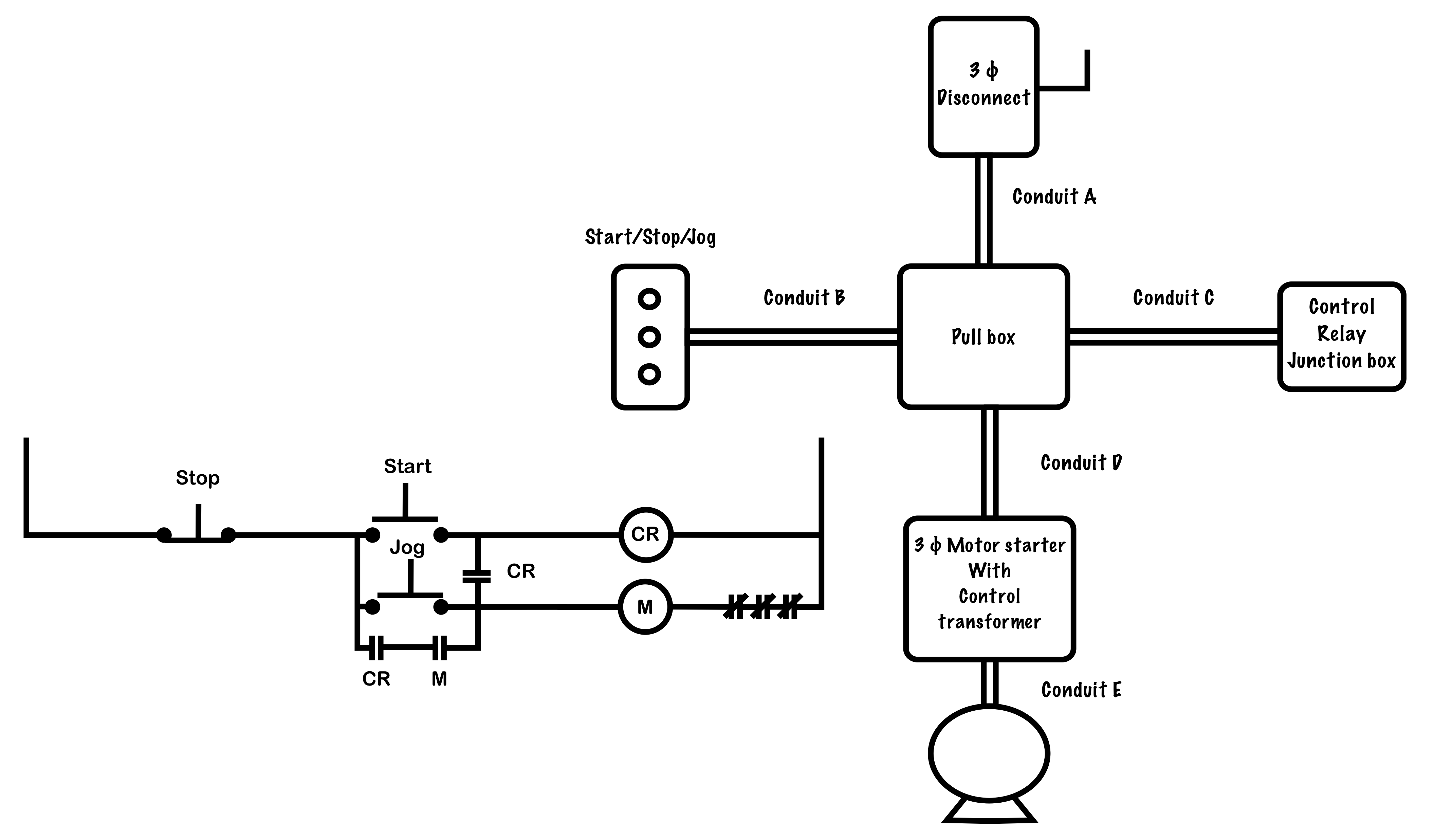
If this is the proposed physical layout of the equipment, how many wires must be pulled through each piece of conduit?
Conduits “A” and “E” will have only the 3-phase power conductors in them. Conduit “D” will have the three power conductors as well as several control conductors. It is permissible for control conductors to share a conduit with power conductors provided their insulations share the same voltage and temperature ratings.
To determine how many control circuit conductors will need to be pulled through each conduit, we apply the numbering system.
First, number the wires in the schematic. Each point that is electrically common gets the same number. Jump up to the next number each time you go through a device or load.
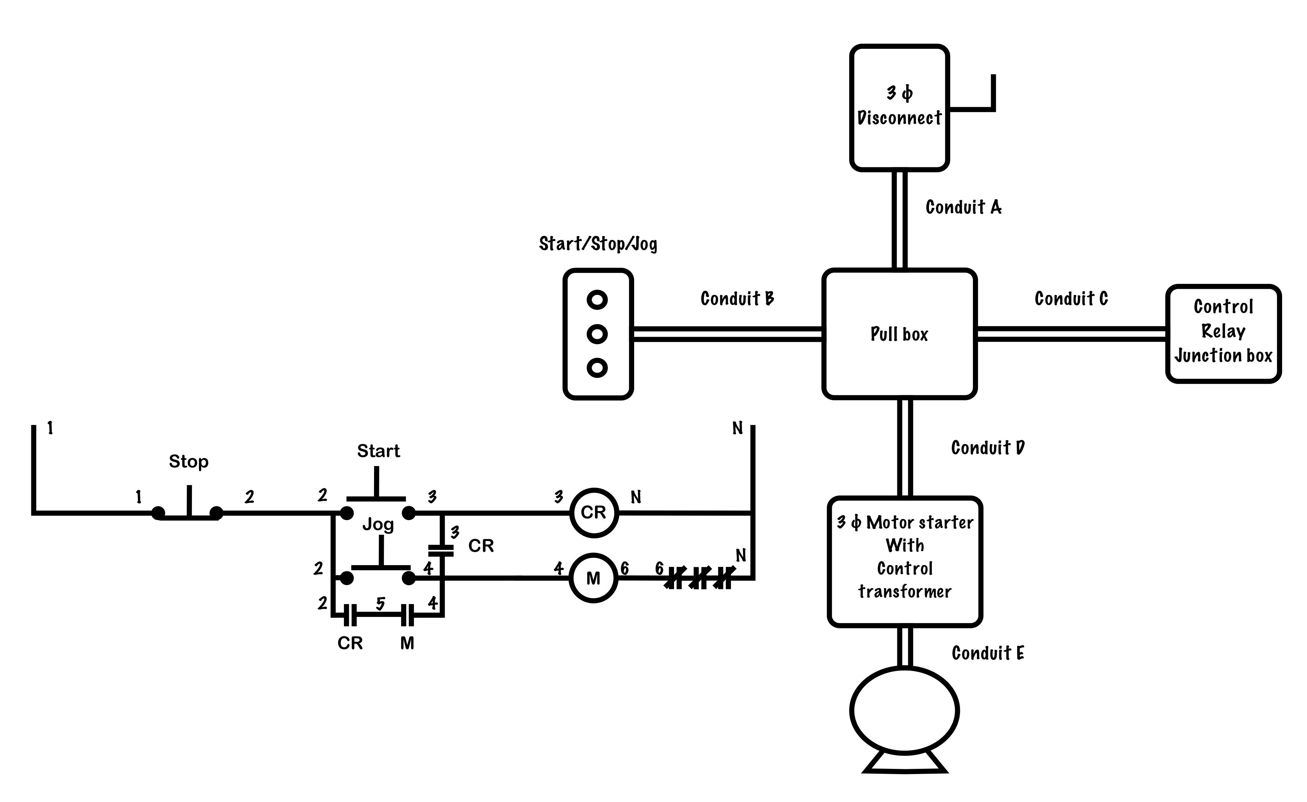
Once the schematic diagram is complete, transfer the numbers of each device to their corresponding location in the wiring diagram. Each point that has the same number needs a wire connecting them.
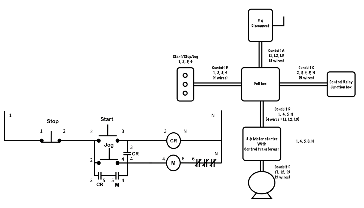
Knowing the total number of wires to pull through a complicated run of the conduit is critical because adding wires afterwards can be impractical and difficult.
Used to convert between wiring and schematic diagrams, the numbering system is a method of identifying and labelling each electrically common point in a circuit. Two wires are considered electrically common if they share an electrical connection with no switches or loads between them, and so would be assigned the same number in the diagram.
In contrast to the Power Circuit, the Control Circuit consists of inputs, in the form of switches, pushbuttons or pilot devices, which when activated, can either directly, or through a magnetic motor starter, energize a load. The Control Circuit often operates at a lower voltage than the Power Circuit for safety and ease of installation.
The difference in electric potential between two points, which is defined as the work needed per unit of charge to move a test charge between the two points. It is measured in volts (V).
A diagram that shows how a circuit works logically and electrically. It uses symbols to identify components and interconnecting lines to display the electrical continuity of a circuit. It is often used for troubleshooting purposes. Also known as a ladder diagram.
Referring to two or more points in a circuit which have no loads or switches between them and have no potential difference between them.
A diagram shows how equipment is laid out and the connections between them. This type of diagram shows the physical relation of all devices in the system, the conductor terminations between these devices, and are commonly used in motor control installations. Also known as a connection diagram.
