Circuits
29 Sump-Pump Circuit
A three-position selector switch may be used to provide either manual or automatic control. When the switch is moved to the HAND position, the magnetic starter is energized. This is useful for testing the condition of the motor and verifying the direction of rotation. When the selector switch is moved to the AUTO position, the magnetic starter is controlled by the opening or closing of the float-switch contacts.
The diagram below shows a sump-pump circuit, while the figure represents the tank that it empties.
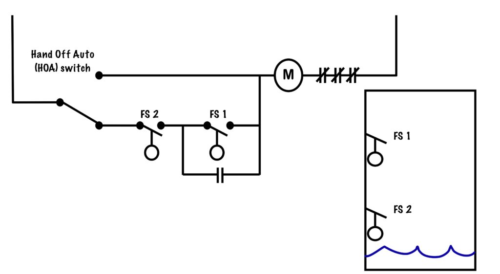
If the water level is low, both float switches are normally open and the motor does not run. If the water level rises, FS 2 will close first, but the motor will not start. Current cannot get past FS 1 nor the normally open auxiliary contacts. If the water level rises to fill the tank and FS 1 closes, the motor will energize and start pumping water out of the tank and very quickly FS 1 will open again.
This is where having two pilot devices allows us a greater range in sensitivity. Even though FS 1 opens almost immediately, the auxiliary contact keeps the motor running until the tank is fully emptied and FS 2 opens. With only a single pilot device the motor would only drain a small portion of the tank and would be subjected to multiple starts and stops. Using two pilot devices to control the motor allows for more efficient operation of the motor.
This circuit shows the arrangement for a tank-drain function. A simple rearrangement of contacts can provide a tank-fill function as well.
A device for making or breaking the connection in an electric circuit.
A contact that under normal conditions does not have continuity through it. When the contact changes its state it permits the flow of current by closing its contacts. Can be associated with pushbuttons, pilot devices or magnetic contactors.
Contacts on a magnetic starter that are not Horsepower rated. Can come as either normally-open or normally-closed and can be used as maintaining contacts, electrical interlocks or control for pilot lights.
An auxilary device that provides indication or control of a process to an operator. Pilot devices include automatic switches such as float and pressure switches, as well as indicating lights.
The conducting part of a switch that makes or breaks a circuit.
