Motor Starters and Contactors
17 Timers

Whenever a motor is started, it draws an initial inrush current. If several motors are to be started simultaneously, these combined inrush currents could cause line disturbances throughout the system and cause nuisance tripping of overcurrent devices.
If two or more motors are controlled from the same pushbutton station, it may be desirable to provide a time interval between their starting. One of the ways that we can accomplish this is to use timing relays.
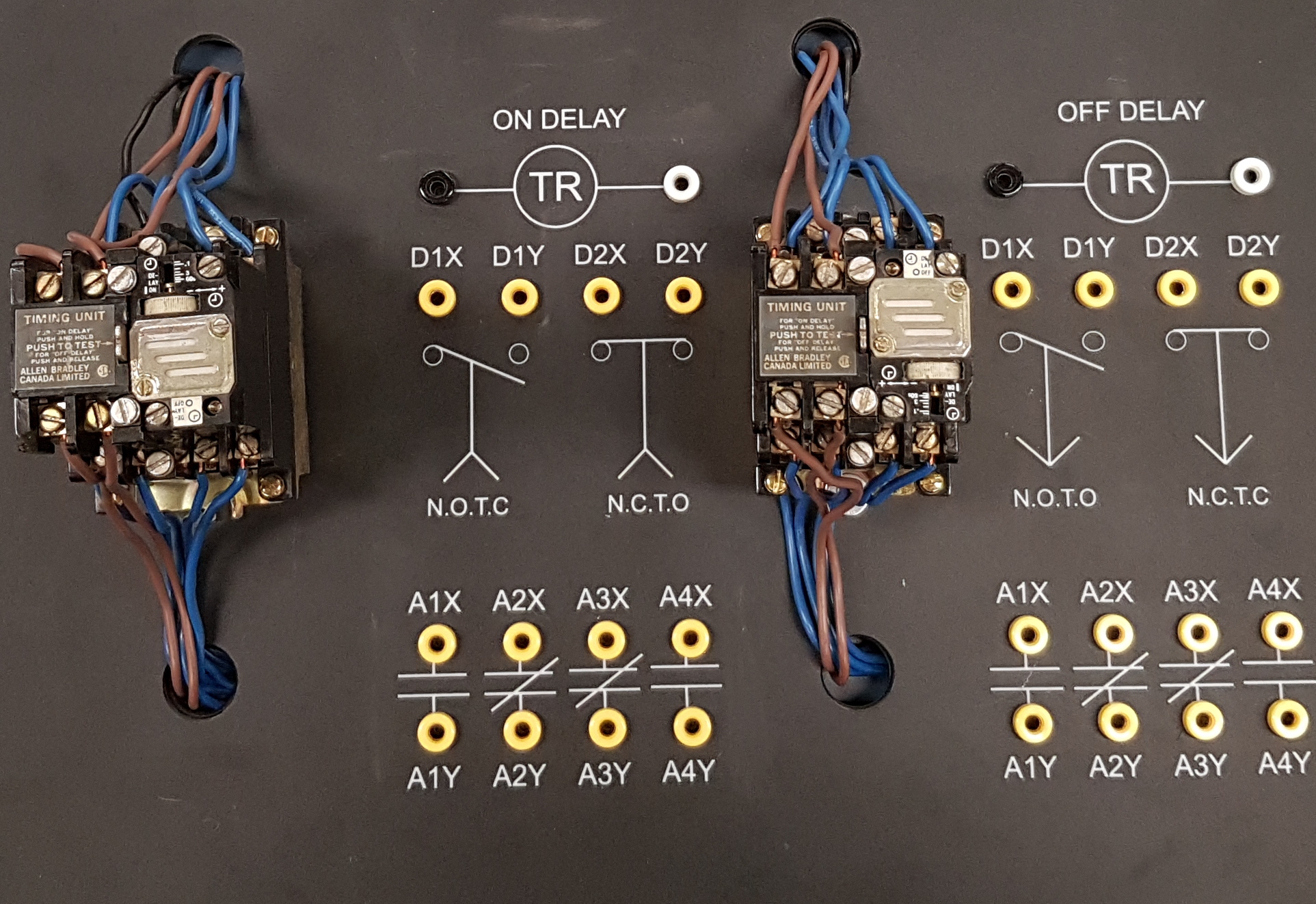
Timers are similar in construction to control relays in the sense that they have a low-voltage armature and coil that opens or closes a set of contacts when energized. The distinctive quality of timers is the addition of some sort of delay mechanism that prevents the auxiliary contacts from changing their state for some pre-set amount of time.
Timers come in two classes: On-delay timers and off-delay timers.
On-Delay Timers

These are commonly used in circuits where we might want to start two motors from the same pushbutton station but with a slight delay to minimize line disturbances due to inrush. The timing contacts for the on-delay timer can be either normally open, timed to close (NOTC), or normally closed, timed to open (NCTO).
On-delay timers delay their action when the coil is energized and revert to their original state instantly when de-energized. Some timers will have instantaneous contacts in addition to their timed contacts.
When looking at the schematic symbol for timed contacts, the arrowhead indicates the direction of the timing action. Some schematic drawings show timed contacts as instantaneous contacts identified with their timing behavior.
Off-Delay Timers

These are commonly used in circuits where we might want to stop two motors from the same pushbutton station but allow the second motor to run for an additional period of time. This arrangement is commonly used in furnace HVAC systems and conveyor belt circuits. The timing contacts for the off-delay timer can be either normally open, timed to open (NOTO), or normally closed, timed to close (NCTC).
Off-delay timers change their original state instantly when energized. And delay their action when the coil is de-energized. Some timers will have instantaneous contacts in addition to their timed contacts.
When looking at the schematic symbol for timed contacts the arrowhead indicates the direction of the timing action.
Some schematic drawings show timed contacts as instantaneous contacts identified with their timing behavior.
The initial high value of current produced when an inductive load is first energized.
A sharp and fast rise in current over a short period of time (fractions of a second) where the value of current is far greater than the nominal line current.
A momentary contact device that has a built in spring to return the button to its normal position once release. Available with either normally-open, normally-closed or both sets of contacts.
Used when additional auxiliary contacts are needed in a control circuit, a control relay is a magnetic contactor which is not designed for the energization of motors, and does not have built in overload protection.
With respect to magnetic contactors, the armature or plunger is the movable part of the magnetic circuit. When a coil is energized the armature is pulled in, opening and/or closing a set or sets of contacts.
The conducting part of a switch that makes or breaks a circuit.
Contacts on a magnetic starter that are not Horsepower rated. Can come as either normally-open or normally-closed and can be used as maintaining contacts, electrical interlocks or control for pilot lights.
A contact that under normal conditions does not have continuity through it. When the contact changes its state it permits the flow of current by closing its contacts. Can be associated with pushbuttons, pilot devices or magnetic contactors.
A contact that under normal conditions has continuity through it. When the contact changes its state it interrupts the flow of current by opening its contacts. Can be associated with pushbuttons, pilot devices or magnetic contactors.
A diagram that shows how a circuit works logically and electrically. It uses symbols to identify components and interconnecting lines to display the electrical continuity of a circuit. It is often used for troubleshooting purposes. Also known as a ladder diagram.

