Learning Task 1
Describe Rainwater Collection Systems
Introduction
What is Rainwater Harvesting?
Rainwater harvesting (RWH) is the ancient practice of collecting and storing rainwater for future use. It makes sense to collect and re-use water from roofs for non-potable uses instead of disposing of it. Although the frequency of extreme weather events may suggest otherwise, the world supply of potable (safe for human consumption) water is slowly and steadily dwindling, and better stewardship of potable water supplies must be considered to preserve it for future generations. With careful planning, safety measures and education, the use of harvested rainwater can lessen our dependence on our potable water supplies for uses that don’t require the water to be potable such as for toilet flushing and lawn irrigation. Any other uses of harvested rainwater, unless treated, inspected, and certified to acceptable standards, are discouraged and, in most cases, not permissible.
The following description of a rainwater harvesting system is found in the British Columbia Plumbing Code 2018, Division A: Compliance, Objectives and Functional Statements:
“Harvested or recovered rainwater commonly refers to a type of auxiliary water supply that is collected from external surfaces of buildings or other hard-surfaced areas not exposed to vehicular or pedestrian traffic.”
The above reference of a RWH system being a type of “auxiliary system” prohibits it from being interconnected with a potable water system in any building, with or without backflow protection.
The construction community supports the use of green building technologies in the design and construction of homes and buildings. The practice and process of rainwater harvesting for non-potable reuse is one example of green building technologies that improves our housing stock, conserves water, and has multiple benefits for both the homeowner and community. This module outlines the practice of collecting, storing, and reusing rainwater from roofs for non-potable purposes.
Why Rainwater is Non-Potable
Water quality is determined by its microbiological, chemical, and physical properties (e.g., pH, colour, odour, turbidity, and bacteria). Municipal tap water has been filtered, treated, and tested at a municipal facility to meet a mandated standard of quality, making it potable.
Although seemingly pure, rainwater has the potential to harbour pathogenic organisms (e.g., E. coli) that would be harmful to humans if consumed and is therefore considered non-potable. Currently, the intent of the National and BC Plumbing Codes is that non-potable systems be used only for the flushing of toilets and urinals, and for sub-surface irrigation. With the supply of potable water becoming increasingly scarce and contaminated, this will likely change at some point in the future. However, at this time, any other use is prohibited.
Plumbing harvested rainwater into a home for permitted non-potable uses requires planning and design considerations to address site conditions and follow mandated installation and inspection requirements. The homeowner, homebuilder, or contractor installing a rainwater harvesting system is required to obtain the necessary permits and call for all the necessary inspections. Due to the complexity of these systems, homeowners are encouraged to consult with and employ a certified plumber, electrician and/or engineer to design and install a rainwater harvesting system.
Installing a System
CAN/CSA B128.1-06 “Design and installation of non-potable water systems” and CSA B128.2:06 “Maintenance and field testing of non-potable water systems” are CSA (Canadian Standards Association) publications that can be relied upon for acceptable installations within most jurisdictions. Product suppliers may also provide guidance on the design of a system and can offer recommendations to contractors familiar with the installation of rainwater harvesting systems and associated components.
The following information outlines key points in the process involved when one wishes to install a rainwater harvesting system for internal, non-potable use.
Permits
The installation of a rainwater harvesting system may require specific permits. Check with the local Authority Having Jurisdiction (AHJ) before beginning an installation. Permits usually require scaled drawings and the work may need to be done by a licensed contractor unless allowable through a homeowner’s permit. Regardless, if a permit is required it must be obtained before any work can start.
Rough-in for Future Use
Roughing-in for the future installation of a rainwater harvesting system in new construction provides homeowners and builders with an option for future use, while saving initial capital costs, meeting existing green building certification compliance, and providing future growth opportunities to the building. Homeowners and home builders must be aware that any portion of the system that is roughed-in will require inspections, and meet all safety codes, even if the system is not finalized or commissioned.
Inspections
The person or company who obtains the permit is also responsible for obtaining inspections at the frequency required by the AHJ.
What are the Benefits of Rainwater Harvesting?
There are several benefits to a residential rainwater harvesting system for non-potable use, including:
- Protecting and conserving municipal and private potable water supplies. Toilet flushing accounts for most of the water use in a house, so reducing water use by toilets and urinals on a municipal system would also reduce the water needed to be treated and delivered to customers. This may also lessen the need to upgrade sections of piping grids that supply new housing developments. On a private well, this translates to less depletion of the water table.
- Reducing the amount of stormwater runoff that must be safely handled. Intercepting, treating, and using roof runoff lessens the volume of stormwater that has to be dealt with on both private and public property.
- Reducing homeowners’ potable water use. This means less water needed to be supplied by a municipal system or by a homeowner’s well if on a rural property. Less water used that is supplied through a meter results in lower water costs to the consumer. Less well pump operation translates over time to lower maintenance costs.
Plumbing Code References
A rainwater harvesting system is a non-potable water system, and as such is dealt with in Division B Part 2 of the BC and National Plumbing Codes.
Section 2.7. Non-Potable Water Systems
2.7.1. Connection
2.7.1.1. Not Permitted
- A non-potable water system shall not be connected to a potable water system.
2.7.2. Identification
2.7.2.1. Markings Required
- The location of non-potable water discharge and non-potable water piping shall be identified by markings that are permanent, distinct, and easily recognized.
2.7.3. Location
2.7.3.1. Pipes
- Non-potable water piping shall not be located
- where food is prepared in a food-processing plant,
- above food-handling equipment,
- above a non-pressurized potable water tank, or
- above a cover of a pressurized potable water tank.
2.7.3.2. Outlets
- An outlet from a non-potable water system shall not be located where it can discharge into
- a sink or lavatory,
- a fixture into which an outlet from a potable water system is discharged, or
- a fixture that is used for the preparation, handling or dispensing of food, drink or products that are intended for human consumption. (See Note A-2.7.3.2.(1).)
2.7.4. Non-Potable Water Systems
2.7.4.1. Non-potable Water System Design
(See Note A-2.7.4.1.)
- Non-potable water systems shall be designed, fabricated, and installed in accordance with good engineering practice, such as that described in the ASHRAE Handbooks, ASPE Handbooks and CAN/CSA-B128.1, “Design and Installation of Non-Potable Water Systems”.
- Non-potable water systems shall only be used to supply water closets, urinals, and directly connected underground irrigation systems that only dispense water below the surface of the ground.
Now complete Self-Test 1 and check your answers.
Self-Test 1
Self-Test 1
- According to both the NPC and BCPC, what are the only acceptable uses for non-potable water systems?
- Exterior hosebibbs and toilet flushing
- Toilet flushing and underground irrigation
- Toilet flushing and above ground irrigation
- Laundry, exterior hosebibbs and toilet flushing
- A harvested rainwater system is categorized in the plumbing codes as what type of system?
- Illegal
- Backup
- Auxiliary
- Unauthorized
- What is the code requirement for interconnecting a potable water system with a non-potable water system?
- They may never be interconnected
- They may be removeable swing joint
- They may be interconnected through a DCVA
- They may be interconnected through an RPBA
- Why is rainwater considered to be non-potable?
- It hasn’t been treated to acceptable certified standards
- It hasn’t been delivered through a water service pipe
- It hasn’t been delivered by a tanker truck
- It hasn’t been supplied from a well
- What section of the plumbing code deals specifically with harvested rainwater systems?
- Division A Part 2
- Division A Part 7
- Division B Part 2
- Division B Part 7
Check your answers using the Self-Test Answer Keys in Appendix 1.
Section 1: Catchment and Conveyance
Rainwater Collection and Conveyance
Rainwater harvesting requires collection of rainwater from acceptable catchment areas and moving it to a storage tank, sometimes referred to as a “cistern”. This section describes the preferred roof types for rainwater collection, an overview of gutters and leaders, and details for directing rainwater through conveyance pipes to a storage tank.
Roof Types
Roofs are the only surface permitted for residential rainwater collection. Paved surfaces and lawns are not allowed as catchment areas because of their potential for contamination from pesticides, vehicle oils and other pollutants. A roof’s composition will play a part both in its collection efficiency and the quality of rainwater it produces. If very high-quality rainwater is desired, roofing materials with NSF P151 certification should be used. Selection of roofing materials, coatings, paints, and gutters that have this certification will not impart levels of contaminants greater than those specified in the U.S. EPA’s “Drinking Water Regulations”.
The most common roofing materials and their considerations are detailed below. The term “collection efficiency” refers to a material’s ability to allow as much rainwater as possible to make its way to the gutter without being slowed or absorbed by the roofing material.
- Asphalt shingle: Asphalt is the most common roofing material in residential construction and is sufficient for rainwater collection. Collection efficiency from asphalt is reduced due to its rough surface and tendency slow down and evaporate surface water. Additionally, particulates and other contaminants can dislodge from asphalt shingles, which can negatively affect rainwater quality.
- Metal roofing: Because of its smooth, clean surface, metal roofing has higher collection efficiency and is generally the recommended option for rainwater harvesting systems. In some suburban communities with set architectural guidelines, homeowners may not be able to choose this roofing option.
- Other roofing materials: Wood shingles (or shakes), recycled or non-recycled rubber, clay tiles, and lightweight concrete tiles are also acceptable materials for catchment surfaces; however, because of their varied rough surfaces, they are subject to lower collection efficiencies.
Built-up roof membranes and “green roof” installations are not typically recommended for rainwater harvesting as they may add contaminants to the water collected. As well, overhanging foliage such as tree limbs should be avoided due to the increased likelihood of leaves and bird droppings landing on the roof.
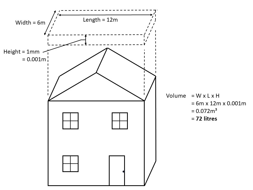
How much water can be collected?
In theory, one litre of water can be collected for every millimetre of rainfall landing on one square metre of collection surface.
Total roof area (m2) × local rainfall intensity (mm) = Potential collection (Litres)
This is the same procedure that was used during the storm drainage sizing exercises in previous modules.
Although theoretically the calculation equation is very similar, in practice the calculation of potential collection volumes for a rainwater harvesting system is much more complex and consequently will not be covered in this module.
The relationship between the catchment area and the volume of rainwater collected is simple – the larger the catchment area, the greater the quantities of rainwater that can be collected.
The catchment area has a significant impact on both the design and water savings potential of RWH systems. In general, it is recommended that the size of the catchment area used for an RWH system be as large as possible to maximize water savings. For most RWH systems collecting rainwater from a roof catchment, the size of the catchment area is usually predetermined by the size of the existing house or building. In such cases, one means of collecting additional rainwater is to utilize multiple roof catchments and convey rainwater to one central or “communal” storage tank.
Alternatively, it may sometimes not be feasible or beneficial to collect rainwater from the entire catchment area due to rainwater quality concerns, location/placement of rainwater storage tank or for other reasons.
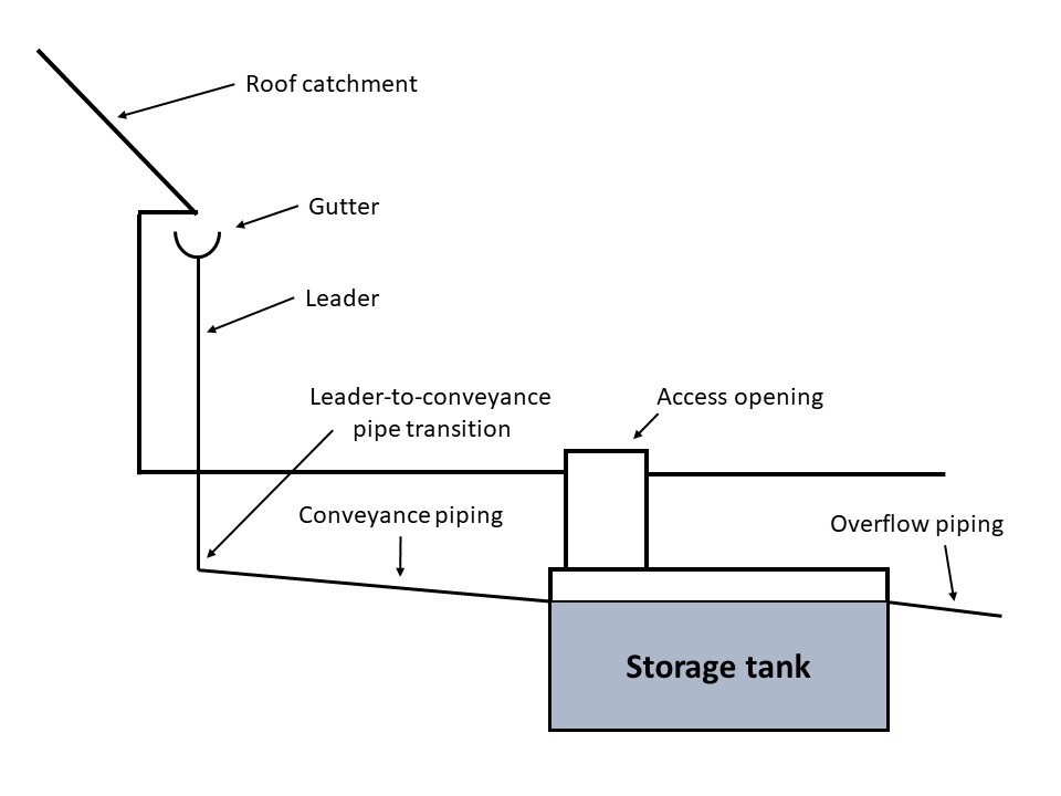
Conveyance of Rainwater to the Storage Tank
Once collected from the catchment surface, rainwater is transferred to the rainwater storage tank through a series of components, referred to as the “conveyance network”. An illustration of a typical conveyance network for a residential household is shown below.
Gutters and leaders
Rainwater will run from the roof surface, accumulate in the gutters (eavestroughs) and travel by gravity through leaders (downspouts) to piping that will carry it to the storage tank. Standard gutter and leader sizes and installation methods are sufficient for a residential rainwater harvesting system. Most gutters are 125 mm (5″) “K-style” aluminum or galvanized steel, with a slope toward the leader locations of between 0.5 and 2 percent. Slopes of less than 0.5% may cause the gutter to overflow in times of heavy rainfall; slopes of more than 2% will be noticeable to the eye from the street and are not aesthetically acceptable.
Typical leaders are 50mm × 75mm (2″ × 3″) or 75 x 75 mm (3″ × 3″) aluminum or galvanized steel. Aluminum is most common, however the plumbing codes list other materials that are also acceptable.
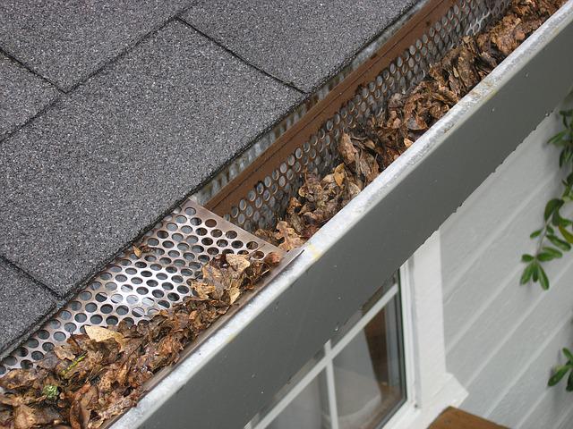
Screening systems for gutters are available that keep leaves and debris out while allowing roof runoff in. These are highly recommended when a roof is a catchment area for a RWH system.
If rainwater is to be collected during the winter months, extra consideration should be made to reduce ice buildup at gutter and leader bends and elbows.
Leader location
It is important to plan leader locations both in relation to the building’s architecture and to the location of the rainwater storage tank. Downspouts should be as near the storage tank as possible to reduce the length of conveyance pipe while collecting rainwater from the full roof surface. Leaders should not be located at inside corners of walls nor inside the building envelope unless absolutely necessary. Additionally, leaders will require some form of inlet screen or filter and a connection to conveyance pipe at or near grade. For aesthetic reasons, homeowners may wish to hide downspout and filtration devices from sightlines.
Conveyance pipe
The conveyance pipe transports rainwater from the leader to the storage tank. Required materials and code issues are detailed below.
- Material: Where conveyance pipe is above grade and exposed to the sun, UV-rated pipe must be installed. For underground installation, a minimum of PVC sewer grade pipe (SDR35) or ABS pipe is required. Higher grades of pipe, such as Schedule 40 PVC, are preferred due to their thicker, more durable wall construction which can help minimize the possibility of breakage. Pipe material must meet the requirements of all applicable codes and standards.
- Size: In accordance with National and BC Building Code rainfall amounts, a minimum size conveyance pipe (storm building drain) is dictated with the pipe size appropriate for the load it carries and the slope it is installed at.
- Slope: 2 percent slope is industry standard although less slope is allowable for larger pipe sizes. Where conditions allow, greater than 2 per cent is ideal for increasing the drainage rate and decreasing the possibility of rainwater freezing during colder months.
- Permanent warning tape and tracer wire: In accordance with CAN/CSA B128.1-06 Clause 12.3.9, buried, non-metallic pipes should have permanent warning tape and tracer wire installed a minimum of 300 mm (12″) above the pipe. There is no such requirement within the plumbing codes.
- Backfill: Pipes must be located on a proper drainage bed in an appropriately sized trench and backfilled in accordance with applicable codes and regulations.
- Winter considerations: If a homeowner wishes to collect snow melt during the winter months and the conveyance pipes could not be buried below the local area frost penetration depth, then insulation should be installed above the pipes to prevent the snow melt from freezing inside the pipe. The preferred insulation type to use is rigid extruded polystyrene (XTPS) foam insulation. Using heat trace wire will keep water from freezing in the pipes, but it is energy intensive and not the suggested method for winterization.
When designing and installing a conveyance network, a few issues must be considered, including but not limited to:
- sizing and placement of conveyance piping
- site conditions and location/placement of storage tank
- cold weather issues
- rainwater quality.
Size, slope, and placement of conveyance network
To ensure that the conveyance network can handle the runoff from the catchment surface in severe storms, all sections of the conveyance network (gutters, leaders, and drainage piping) must be appropriately sized and sloped to promote rapid water drainage. While the design of gutters and leaders must always conform to building and plumbing code specifications, there are standard sizes and “rules of thumb” for residential applications using aluminum. However, conveyance drainage pipes connecting the bottoms of leaders to the storage tank are considered by plumbing codes to be “storm building drains” and must therefore be selected and installed in accordance with applicable codes and regulations.
When sizing pipes and other parts of the conveyance network, it is important to consider what proportion of the catchment surface a particular section of the network is handling. In most cases, the catchment surface will be divided into sections. For example, a peaked roof will have at least two distinct drainage areas from which rainwater will be collected. Accordingly, it may be necessary to have multiple smaller conveyance drainage pipes that transfer rainwater to a larger pipe leading into the rainwater storage tank.
Site conditions and tank location
When planning a conveyance network, it is important to take into consideration the site conditions and location/placement of the rainwater storage tank. It may be difficult to connect some sections of the catchment surface to the conveyance network due to grading and/or layout of the site, distance to the storage tank or complex roof shapes. For instance, when designing the layout of the conveyance drainage pipe transferring rainwater to a below-ground tank, the length of pipe and pipe slope can affect the burial depth of the tank (for example, force it to be buried deeper below ground). Some tanks, however, cannot be buried below a maximum rated burial depth and, consequently, the location of the tank or the pipe slope may need to be adjusted. Alternatively, a reinforced tank designed for deeper burial may have to be selected.
Another concern when designing conveyance networks leading to below-ground tanks is the presence of buried service lines (gas, water, phone, etc.). An inspection of the site to locate the service lines must be performed to ensure that the planned route is free from buried lines.
Conveyance network material selection
Part of planning the conveyance network involves selecting the appropriate material for each of the network components. Gutters and leaders are generally manufactured out of aluminum or galvanized steel, both of which are considered suitable for RWH systems. When selecting a pipe material, several criteria must be considered. The pipe selected must be rated as suitable for ultraviolet (UV) light exposure and burial (where applicable) and, if the highest rainwater quality is desired/mandated, it must be rated for handling potable water. In addition, the selected pipe must be approved by the applicable codes and regulations. In general, a type of polyvinyl chloride (PVC) pipe, referred to as “sewer grade pipe” or “SDR-35” is recommended for RWH systems, as it meets these criteria. Acrylonitrile-butadiene-styrene (ABS) is another type of pipe that can be used and is typically less expensive than PVC SDR-35 but may not be appropriate for all RWH systems as it is not rated for UV exposure. It is important to note, however, that, even if rainwater is conveyed using a pipe suitable for potable water, this does not imply that rainwater is potable or suitable for potable use.
Cold weather issues
Throughout much of Canada, temperatures often drop below freezing (0°C) during the winter months. During periods of extreme cold weather, rainwater that is outdoors or in an environment that is not temperature controlled (maintained above 0°C) is at risk of freezing. Rainwater can freeze in the conveyance network if it is not drained adequately or if it must travel through extended portions of the network that are not temperature controlled. The installation of rigid polystyrene foam insulation, proper slope, and adequate burial depths will help to reduce the possibility of pipe freezes.
Catchment and Conveyance Guidelines
Catchment areas
- Only roof surfaces are allowable
- collection from green roofs is not recommended
- sections of the roof with overhanging foliage or trim should be avoided where possible
- if rainwater collected from the catchment surface must be of very high quality, materials with NSF P151 certification should be selected
- the catchment surface should be as large as possible
- if a roof catchment material is to be selected and installed in conjunction with the RWH system, material with minimal collection losses, such as steel, should be selected
Gutters and leaders
- aluminum or galvanized steel are recommended
- copper, wood, vinyl and plastic gutter and downspout materials are not recommended
- gutter inlets should be screened to minimize the intrusion of leaves and debris
- if rainwater conveyed through gutters and downspouts must be of very high quality, materials with NSF P151 certification should be selected
- where possible, slope gutters toward the location of the rainwater storage tank
- ensure a minimum slope of 0.5% to 2% (the greater the slope the better) is maintained throughout the gutter length
- make sure gutters conform to applicable codes and regulations
Conveyance piping
- convey rainwater using appropriately sized and sloped components, that conform to applicable codes and regulations
- where possible, multiple roof catchments can be connected to a central or “communal” rainwater storage tank
- protect conveyance piping from freezing or from crushing loads
- record the depth and location of all buried RWH system piping and tanks
- make sure any required cleanouts remain accessible
Now complete Self-Test 2 and check your answers.
Self-Test 2
Self-Test 2
- Which one of the following would be an acceptable catchment area for a RWH system?
- A lawn area
- A parking lot
- A “green” roof
- An asphalt shingle roof
- If a roof with an area of 200 m² is in an area that receives 8mm rainfall, how many litres of rainwater will be available to be collected?
- 1,600
- 200
- 25
- 8
- What is the maximum suggested slope on a gutter?
- 0.5%
- 1.0%
- 1.5%
- 2.0%
- Which one of the following types of pipes is preferred for underground conveyance piping?
- ABS
- SDR-35
- PVC sewer
- PVC Sch 40
- What is the preferred method for keeping underground conveyance piping from freezing?
- Heat tracing
- Heat tracing and insulation
- Polystyrene foam insulation
- Polystyrene foam insulation and adequate burial depth
- According to plumbing codes, what is the horizontal conveyance pipe at the bottom of a leader known as?
- A lateral
- A conveyance pipe
- A storm building drain
- A sanitary building drain
- Why is ABS pipe not a suggested material for exposed conveyance piping?
- Because it is not UV-rated
- Because it is not always available
- Because it is more expensive than PVC
- Because it doesn’t have a smooth interior
Check your answers using the Self-Test Answer Keys in Appendix 1.
Section 2: Rainwater Storage
Once rainwater passes through the conveyance network, it is deposited in a storage tank or cistern located in a basement or below grade outside the house. In certain cases, a rainwater cistern can be located above grade (for summer use only) or in a heated garage. As the storage tank is the most important and usually most expensive component of the rainwater harvesting system, it’s best to consider the options during a home’s design stage if possible. This will allow for some flexibility in the tank’s location, configuration, and slope of conveyance pipe from downspouts.
As the central hub of an RWH system, the rainwater storage tank is directly connected to several pipes and houses some components internally. These components may include some, or all, of the following items shown in the graphic below.
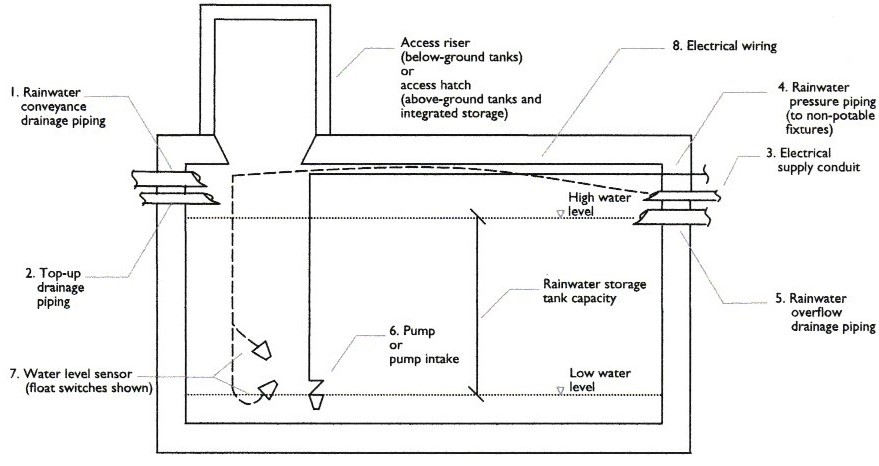
The storage capacity of rainwater storage tanks can also vary, from several hundred litres for a typical rain barrel to thousands of litres for commercially available above-ground or below-ground holding tanks. In addition to acting as the primary storage reservoir, the rainwater storage tank can also be considered as the central hub of an RWH system. It is the central location for handling all the rainwater going into (and coming out of) the RWH system and many important components, such as the pump and water level sensor, are often located directly within the tank itself.
Care must be taken during its selection, installation, and maintenance to ensure the proper functioning and optimal performance of the RWH system. A source of information for tanks for RWH systems is the CSA Standard B128.1:06/B128.2:06 (R2021) “Design and installation of non-potable water systems/Maintenance and field testing of non-potable water systems”. Section 7.0 “Storage Tanks” provides specifications for the design and installation of rainwater storage tanks, including access openings, piping connections, overflow, drainage and venting
Selecting a Tank
Beyond the basic volume capacity, there are a great many factors to consider when choosing a storage tank. These include intended rainwater use, bearing loads, desired storage capacity, site conditions, buried service lines and utilities, site accessibility for excavation and installation, available space for the storage tank, property right-of-way, property setbacks, below-grade burial depth, local rainfall quantities, available roof catchment area, and budget. While the norm is to install only one storage tank, other factors such as property restrictions, structural limitations or buried utilities may require dividing a system into two or three separate tanks.
Tank types
Storage tanks can be fabricated from many different materials, including high-density polyethylene (plastic), fibreglass, steel, concrete, and crate-and-bag. A homeowner or system designer may choose to integrate a concrete storage tank into the foundation wall (a cast-in-place cistern), place it in an appropriate location in the front or back yard, or size the mechanical room with sufficient space to fit a plastic or fiberglass storage tank inside the home. An engineer’s approval is required if a concrete storage tank will be integrated into the home’s structure whether it be cast-in-place, located below a suspended concrete slab, or located on a floor other than a basement or garage.
The selection of one of these materials for a rainwater storage tank will largely depend on local availability, as well as on cost, tank placement (above ground or below ground or integrated), storage requirements, site accessibility and/or engineering specifications. In recent installations, above-ground tanks are often plastic while integrated tanks are usually cast-in-place concrete. Below-ground tanks are usually precast concrete or plastic. For an existing home, a more likely choice will be a plastic (high-density polyethylene), fiberglass, or precast concrete storage tank, located outside of the home at or below grade.
In general, greater economies of scale are seen for concrete tanks than for plastic tanks, making concrete a more desirable material for very large systems. Engineering specifications, such as maximum rated burial depth or minimum required water level, vary for different tank materials and designs. Installation and operational specifications can be sought from manufacturers.
Another consideration is the potential for chemicals to leach from the tank into the stored rainwater, although this is only a concern if rainwater must be of very high quality for a particular end use.
A summary of the types of tanks is as follows:
- Concrete: For longevity and strength, concrete is a tried-and-true option. Depending on its size, a tank can be prefabricated, delivered, and dropped into place using lifting equipment. Alternately, a concrete tank can be formed and poured in place. Concrete tanks are especially beneficial if there are heavy loads, such as vehicles, expected over them. Again, an engineer should be consulted if such an installation is proposed.
- Plastic and fiberglass: These tanks are good options if placement of the tank without the need for heavy lifting equipment is desired. They are very lightweight and strong but are not normally expected to have heavy loads over them so are best installed below ground in a lawn area. A rain barrel is an example of an above-ground plastic tank.
- Steel: Steel tanks are not advantageous due to expected corrosion and aesthetics, and are therefore not commonly found in rainwater harvesting systems. If used, they should be installed fully exposed so that any leakage caused by corrosion can be easily detected. An examples of a steel tanks might be a clean 45-gallon drum that has been used for no previous purpose.
- Crate-and-bag: These are a square plastic “bag” contained within a steel mesh crate. The bag can be light-gauge material due to the steel mesh surrounding it which supplies the strength needed. These are commonly seen on flatbed trucks and in the beds of pickups for portable liquid transport. Their construction makes them very portable but, like the steel tanks, they are not normally used in a RWH system. However, like the steel tanks, they could be utilized as a temporary means to establish the amount of collection onsite to determine the size of permanent tank needed.
Tank sizing
Sizing a rainwater storage tank may be the most comprehensive step to the overall system design. Sizing will typically be based on the amount of water a homeowner wishes to conserve annually and may involve either a general estimate or a detailed assessment of application use and water demands. Sizing of the storage tank will depend on the intended and combined rainwater “load” including the number of toilets in regular use, outdoor irrigation demands, roof catchment area, local rainfall quantities, and potential growth as well as the number of people in the house (toilet use).
Proportion of total rainfall collection expected (“collection efficiency”)
In general, the larger the tank, the greater the volume of rainwater that can be collected and stored during rainfall events. However, this is true only up to a certain point, after which other factors, such as local rainfall patterns, roof catchment area and rainwater demand will limit the amount of rainfall that can be collected and utilized by the system.
Collection efficiency, defined as the percentage of rainfall landing on the roof that will find its way to the storage tank, depends on several site-specific and seasonal factors. Depending on geographic location and site specifics, the collection efficiency can fluctuate between 65% and 85%, with 75% used as the average. Common reasons for water loss include:
- site-specific water losses that are affected by roof material, overhanging branches, and prevailing winds
- collection system losses such as overflow and spillage from undersized piping and inefficient filters, and
- seasonal factors that decrease the proportion of the rain collected such as snowfall that does not melt, light shower rainfalls in the summer, the need to divert water during spring pollen season, and the need to shut down and clean the system after pollen season.
Remembering that 1 m² of catchment area x 1mm of rain will produce 1 litre of water, if 100% of the annual rainfall were expected to be captured and stored, then the roof catchment area (in m²) multiplied by the annual precipitation (in millimeters) equals potential water collection (in litres). An example calculation of the annual amount of rainwater to be collected would be as follows:
If a roof is calculated to have a 100 m² roof catchment area and is in a city or municipality that has an annual precipitation rate of 1,538 mm, then an expected annual rainwater load can be calculated as:
100 m² × 1,538 mm = 153,800 litres
Using an average collection efficiency of 75%, then an expected actual amount of rainfall that could be captured and stored would be calculated as:
153,800 litres ×75% = 115,350 litres (approx. 25,351 Imp. Gallons)
If the tank were expected to hold the entire year’s worth of water, it would have to have a volume of:
115,350 ÷ 1,000 l/m³ = 115.35 m³ (approx. 4,073 ft³)
Obviously, this tank would be enormous if it were expected to hold the full year’s rainwater supply. Realistically, water would constantly be drawn off to supply toilet and irrigation needs, so therefore the tank would not have to be sized to hold a year’s worth of water. There are a great many other factors involved in tank sizing, as were mentioned above, such as number of people in the household, month-by-month expected precipitation, lawn and shrub watering frequencies and amounts, available area, cost and so on.
Therefore, manufacturers and suppliers of tanks for rainwater harvesting systems should be consulted. Their expertise can offer more accurate estimations of tank size. Thus, the estimation of the tank size needed for an RWH system will have one of the following outcomes once in place:
- Too small – much of the collected rainwater overflows during rainfall events. Significant improvements in collection efficiency can be achieved with minor incremental increases in storage volume.
- Optimum range – rainwater tanks in this range provide the best balance between collection efficiency of the RWH system and minimizing its size and cost.
- Too large – rainwater tanks in this range rarely fill to capacity. A smaller tank can be used without a significant drop in the collection efficiency of the RWH system. An oversized rainwater storage tank, however, may be desirable if stormwater management is a strong driver for installing an RWH system.
Ultimately the correct size of tank will truly only be discovered once it is in place and in operation over several years, therefore it is important to consult as many sources of information as possible before deciding on a tank size.
Tank location
The optimum location of a tank on a given site depends on many issues such as:
- required fall of the gravity flow conveyance network
- placement of tank (above or below ground, or integrated into a building)
- desired/required tank capacity
- regional climate (e.g., freezing issues)
- site conditions (site grading, accessibility, and space availability)
- proximity to other RWH components (catchment area, overflow discharge location, control components of pump and pressure system)
- potential interference with site services (gas, electricity, water, stormwater, wastewater, phone or cable lines)
Following consideration of each of these issues, it is likely that trade-offs must be made, for instance, the optimum tank storage capacity may be too large to be accommodated at the site, or the optimum location for the tank may be in an area that is difficult to access, and multiple smaller tanks may be a better choice.
Tank placement
The following table outlines some of the advantages and disadvantages associated with the different placement options regarding rainwater storage.
| Tank Placement | Advantages | Disadvantages |
|---|---|---|
| Above ground storage |
|
|
| Below ground storage |
|
|
| Integrated storage |
|
|
Cold weather issues
Throughout much of Canada, temperatures often drop below freezing (0°C) during the winter months. Rainwater stored outdoors or in an environment that is not temperature controlled (maintained above 0°C) is at risk of freezing, either in the storage tank itself, in the pump pressure piping, or both. Water freezing in either location may cause short term blockages and service disruptions or, in the long term, the RWH system may become damaged through the expansion of ice in the system. To minimize these risks, the following two options should be considered.
- Winter decommissioning: If an outdoor above-ground tank or other setup in a non-temperature-controlled setting is used to store rainwater, the tank, pump, and pressurized lines shall be drained of all rainwater prior to the onset of cold weather and use of the system shall be discontinued during the winter months.
- Winterizing the RWH system: An RWH system can be used year-round in cold climates if it is:
- located in a temperature-controlled environment such as a heated garage or basement in the case of above-ground or integrated rainwater storage; or
- located in a below-ground tank that is buried below the local frost penetration depth.
The first option is generally the simplest and least costly system to design and install. These benefits, however, are largely offset by the significant reduction in rainwater that can be collected and used throughout a given year, as well as by the potential damage to system components if decommissioning occurs too late or not at all. As well, the first option does not allow toilets to be supplied with harvested rainwater and is therefore limited to an irrigation-only RWH system.
The second option, to winterize the system, is more complicated and more costly but is preferred since it enables the RWH system toilets to operate throughout the entire year and ensures system components are protected from frost damage.
In either option, the sub-surface irrigation system would need to be properly valved so as to isolate and drain it before winter.
Additional details of the rainwater storage tank
Installations: If a prefabricated underground storage tank is used for a rainwater harvesting system, it must comply with Clause 4.1. of CSA B66:21 “Design, material, and manufacturing requirements for prefabricated septic tanks and sewage holding tanks”. If a storage tank is going to be integrated into the building or have heavy structural loads on top of it (i.e., vehicles), the design supporting the loads must be approved by a professional engineer.
Call before you dig: Provincial locating services (e.g., “BC One Call”) should be contacted to locate any underground service lines where a storage tank and its associated underground piping is planned to be buried. This service combines all underground utilities’ locations into one information request. The installation, bedding and backfilling of storage tanks should be carried out as per the manufacturer’s installation requirements.
Access: The entryway (access hatch) of storage tanks needs to be easily accessible and sized with a dimension no smaller than 450 mm (18 in). A 24″ or larger access hatch is recommended to allow for physical entry and the installation and regular maintenance of any internal equipment inside the cistern. All access hatches need to be drip-proof and non-corrosive. Any persons entering the storage tank will need to comply with Provincial Confined Space Entry Regulations.
Tank connection and pest control: All connections to the storage tank must be properly sealed and watertight. Any additional openings that are connected to storage tanks which are larger than 150 mm (6 inches) should have lockable covers. Any connections or openings exposed above grade should include insect or vermin screens to prevent access to the cistern.
Overflow pipe: The overflow pipe exiting the storage tank needs to be sized to match or exceed the size of the inlet conveyance pipe and should terminate with a screen.
Calmed inlet: The conveyance pipe entering the storage tank should be brought down near the bottom of the tank and have a 90-degree bend or a U-shaped bend. This ensures incoming rainwater is directed away from the bottom of the tank, not stirring up any potential sediment that has accumulated.
Venting: Storage tanks require venting to allow for proper drainage and to release any build-up of humidity or any noxious gases. Venting through the conveyance pipe and the overflow pipe is usually sufficient for a residential installation.
Dead space: There is normally a 4″ – 6″ unused portion of rainwater at the bottom of the storage tank, typically called the “dead space” and retained to ensure the submersible pump or the suction line does not run dry. This is established through the correct setting of the height of the pump on/off switch.
Cold weather considerations: Underground storage tanks should be installed below the frost penetration depth. If this is not possible, the storage tank should be covered with rigid XTPS (extruded polystyrene) foam insulation, or it could be located in a heated or temperature-regulated space (basement or heated garage). Above-grade storage tanks need to be drained and decommissioned during the winter.
Management Guidelines
Rainwater tanks should be inspected at least once a year for the following:
- Leaks
- For below-ground storage tanks, leaks may be identified through poor performance of the RWH system (for example, the make-up water system operates often), from moist soil conditions surrounding the tank and/or excessive settling of the tank in the excavated space
- For above-ground storage tanks and integrated storage, leaks can be identified visually by examining the area surrounding the tanks, or through poor system performance or soil moisture (if applicable)
- Accumulation of debris
- Sediment may accumulate on the bottom of the tank and, depending on the treatment provided, appear at the point of use. In such cases, the location (height) of the pump intake may need adjustment. Adjust the location of the pump intake so that it is located 100 – 150 mm [4 – 6 in.] above the bottom of the tank
- If sediment is still detected at the point of use, pre-storage and/or post-storage treatment devices may need to be installed (or cleaned/maintained) to improve rainwater quality (refer to chapter
- Rainwater quality and treatment
- In some cases, it may be necessary to remove the accumulated sediment at the bottom of the tank. Place a pump capable of handling large debris and/or solids (for example, a suitable sump pump or effluent pump) at the bottom of the tank to pump out the sediment layer.
- Note: removal of sediment and/or tank cleaning is not generally recommended on an annual basis, as this can destroy beneficial “biofilms” in the tank. These biofilms may contribute to improved stored rainwater quality.
Winterizing or decommissioning are the two choices for protecting the RWH system from freezing.
Winterizing
If the system must operate year-round, and the tank and all related components cannot be installed below the frost level, consider these steps:
- Install a heating system to maintain air temperatures above 0°C (if tank is indoors).
- Install a water heating system directly inside the rainwater tank
- Install heat trace wire around any components that are above the frost level
- Install insulation on the rainwater tank, around pipes, valves and/or pump
Decommissioning
If the system does not need to operate year-round, consider these steps:
- Drain/blow out with air all the rainwater stored in the tank and the rainwater pressure piping
- Shut off the water supply to the make-up water system (if present) to prevent the tank from refilling
- Disconnect electrical supply to the pump and control equipment
- Disconnect leaders from the conveyance network and have them discharge to grade or other suitable location
- Disconnect fixtures, such as toilets, from rainwater supply and connect to the potable water system
Now complete Self-Test 3 and check your answers.
Self-Test 3
Self-Test 3
- Which one of the following tank placement options would require the approval of an engineer?
- Installing a below-ground plastic tank in a front yard
- Installing a below-ground concrete tank in a back yard
- Forming a concrete tank as a component of the house foundation
- Forming a poured-in-place concrete tank below-ground in the front yard
- Which one of the following tank material choices would provide the most strength and likely last the longest?
- Steel
- Plastic
- Concrete
- Fiberglass
- Tank sizing involves many varying factors. What or who should be consulted when attempting to accurately determine an appropriate tank size for a RWH system?
- The AHJ
- A plumbing wholesaler
- The local plumbing code in force
- Tank manufacturers and suppliers
- Which of the following considerations would likely be most objectionable if choosing to install a plastic above-ground RWH tank in a front yard?
- Ease of handling
- Aesthetics
- Longevity
- Cost
- Which one of the following choices would likely incur little or no extra excavating costs?
- An integrated tank
- A below-ground plastic tank
- A below-ground pre-cast concrete tank
- A below-ground poured-in-place concrete tank
- Who should be consulted before excavating for placement of a RWH tank or its underground components?
- A provincial “One Call” service
- The local water/sewer utility
- The local telephone utility
- The local electrical utility
- What determines the height of the “dead space” in the bottom of a RWH tank?
- The location of the tank overflow
- The height of the pressure pipe outlet
- The placement of the pump on/off switch
- The location of the rainwater conveyance inlet pipe
- What is the purpose of the “dead space” in a RWH storage tank?
- To keep the sediment stirred up
- To ensure the pump does not run dry
- To make sure any sediment doesn’t collect
- To keep the overflow unobstructed from debris
- Which one of the following choices would be considered the best approach to ensuring a RWH tank that has to operate year-round is protected from freezing?
- Install it and all related components below the frost level
- Drain/blow out with air the tank and all related components
- Install insulation around the tank and all related components
- Install heat tracing wire around the tank and all related components
- Which one of the following choices would not be part of decommissioning a RWH system?
- Shut off the make-up water supply to the tank
- Install heat trace wire around the tank, pipes, valves, and pump
- Disconnect toilets from the RWH system and connect them to the potable system
- Disconnect leaders from the conveyance network and let them drain onto the ground
Check your answers using the Self-Test Answer Keys in Appendix 1.
Section 3: Rainwater Quality and Treatment
Rainwater Quality
There are currently no national water quality guidelines that pertain specifically to the use of rainwater. The “Canadian Guidelines for Domestic Reclaimed Water for Use in Toilet and Urinal Flushing (2010)” are not intended for rainwater use but may be applied for multi-residential or commercial systems where there is the potential for direct contact. For single-family dwellings, the quality of rainwater and the need for treatment must be evaluated in the context of connected fixtures. Residentially, these would be toilets specifically, as the plumbing codes prohibit the use of harvested rainwater for any other fixtures.
The quality of rainwater runoff from a catchment surface can be affected in two ways. Firstly, dirt and debris can collect on the roof surface from direct atmospheric deposition (e.g., smog, acid rain, etc.), from overhanging foliage, or bird and rodent droppings. Secondly, the roof material itself can contribute both particulate matter and dissolved chemicals to runoff water. These issues are a concern for all RWH systems.
Treatment can be applied to improve rainwater quality and can take place:
- before storage in the rainwater storage tank (pre-storage treatment) and/or
- after storage in the rainwater storage tank (post-storage treatment).
Pre-storage treatment devices must be incorporated as part of the conveyance network and rely on gravity flow to facilitate the treatment process. Post-storage treatment devices tend to be more rigorous than pre-storage treatment devices and often require pressurized flow and/or electricity to aid in the treatment process. The table below lists some advantages and disadvantages of each.
| Treatment location | Advantages | Disadvantages |
|---|---|---|
| Pre-storage treatment |
|
|
| Post-storage treatment |
|
|
Pre-storage Treatment
Although there are various ways of treating rainwater prior to storage, methods tend to use one of three techniques: first-flush diversion, filtration or settling.
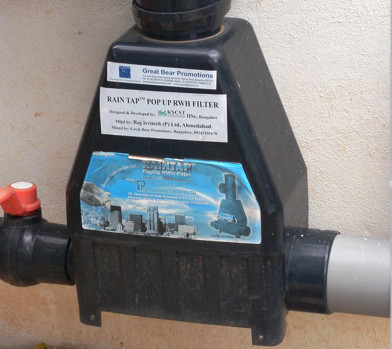
First-flush diversion involves diverting the first portion of runoff (collected from the catchment surface) away from the storage tank. This technique improves stored rainwater quality by preventing the entry of the dirt and debris that collect on the catchment surface between rainfall events, the majority of which are contained in the first portion of runoff (“first flush”).
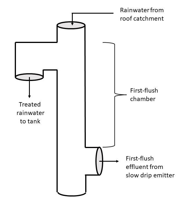
Any sediment or debris is deposited directly into the chamber bottom, which has an outlet with an orifice in it. This allows the chamber liquid to back up and spill the runoff water out to the tank via the upper opening while the liquid containing sediment slowly drains away to a satisfactory location.
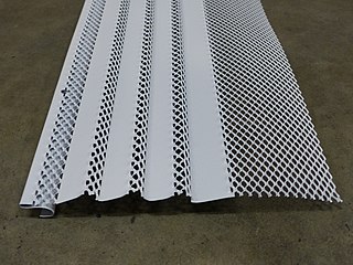
The second method, filtration, involves screening out leaves and large debris from runoff, preventing their entry into the rainwater storage tank. Filtration can take place at or near the catchment surface in the form of screens placed over gutters (referred to as “gutter guards”) or screens placed over roof drains/leaders on flat-roofed buildings. Filtration devices can also be integrated into leaders or other parts of the conveyance network.
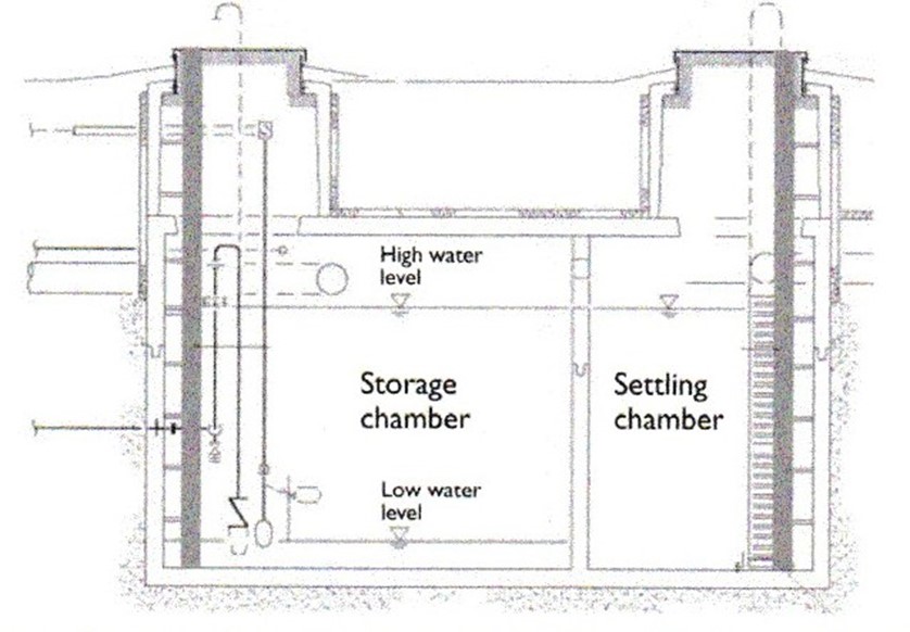
Another pre-storage treatment method is a settling chamber in a rainwater storage tank or a dedicated settling tank. Rainwater from the roof catchment is first conveyed to the settling chamber, where the dirt and debris suspended in the rainwater can settle out and collect as sediment at the bottom of the chamber. The clarified water is then conveyed to the rainwater storage tank or the storage chamber of the tank. A two-compartment storage tank with a settling chamber is shown below.
Post-storage Treatment
Post-storage treatment includes filtration, disinfection and/or treatment for aesthetic issues like colour, taste, or odour. As for pre-storage treatment, there are several different treatment devices available to perform these tasks. A description of these techniques, their applications and a list of available devices/options are provided in the table below.
| Treatment Location | Details | Treatment Options Available |
|---|---|---|
| Filtration | Filtration removes suspended particles from water by passing it through a permeable material.
Water quality issues targeted:
|
Particle filtration (for example, bag/sock or cartridge filter)
|
| Disinfection | Disinfection removes or inactivates micro-organisms by chemical or physical means.
Water quality issues targeted:
|
|
| Aesthetic Issue Treatment | Aesthetic issue treatment removes constituents from water that contribute to colour, taste or odour issues.
Water quality issues targeted:
|
|
Despite having an initial filter which flushes the leaves and other debris from the rainwater, it is recommended that homeowners install some form of post-storage filtration and treatment device. Post storage filtration and treatment will improve the quality of water entering the home from the cistern. Typically, post storage filtration equipment requires a conditioned environment and location in the mechanical room for maintenance and electrical supply. Post storage water treatment typically consists of UV disinfection lamps, particle filters and, potentially, carbon or reverse osmosis filters.
It is important to note that post-storage treatment is normally only considered where harvested rainwater is to be used for potable purposes, which are not the focus of this literature due to being disallowed by plumbing codes.
Treatment Device Selection
When determining the treatment devices required for a rainwater harvesting system, the following questions should be considered.
- What applications will the rainwater be used for?
- What quality requirements do applicable provincial, territorial and/or national codes and regulations specify for the uses under consideration?
- Can the rainwater harvesting system supply enough rainwater to meet the desired uses?
- Can treatment requirements be achieved through the proper design, installation and maintenance of the rainwater harvesting system?
- What are the personal preferences of those using the rainwater and those who are managing the rainwater harvesting system?
- What treatment devices are locally available?
- Are there methods of supplying rainwater of varying qualities to different fixtures, if allowable?
- What is the waste stream that is going to be generated through treatment and how will it be disposed of?
- What are the capital, operational and maintenance costs associated with the treatment devices?
- Who will ensure that maintenance is performed, provide training to maintenance personnel, and pay for the replacement of filters or other components?
Design and Installation Guidelines to Improve Rainwater Quality
Listed below are factors that impact the quality of rainwater in the rainwater harvesting system and can be mitigated through proper design and installation.
| Components of a RWH System | Risk Factors | Design and Installation Best Practices |
|---|---|---|
| Catchment Surface |
|
|
| Conveyance Network |
|
|
| Rainwater Storage Tank |
|
|
| Overflow System |
|
|
Consider other site-specific risk factors and adapt maintenance of the RWH system as appropriate to mitigate the risks to rainwater quality.
Routine Care and Maintenance of Water Treatment Systems
Pre-storage treatment devices should be inspected at least twice a year, or more frequently as required by manufacturer’s instructions and site conditions.
Observe rainwater passing through the devices during a rainfall event or simulate a rainfall event by discharging water from a hose onto the catchment surface. Look for potential problems such as
accumulated dirt and debris blocking flow through the filter, or loose fittings or other problems with the treatment devices such that rainwater is passing through without treatment taking place.
Clean the filtration devices according to the manufacturer’s maintenance instructions and repair as required.
If pre-storage treatment devices need to be decommissioned during the winter:
- drain all the rainwater accumulated in the treatment devices
- disconnect the treatment devices from the conveyance network, and/or
- install pipe, downspouts, or other material to bypass the pre-storage treatment devices and direct untreated water to the tank
Post-storage treatment devices should be inspected at least quarterly, or more frequently depending on manufacturer’s instructions and site conditions.
Observe the devices as water flows through the pressure system, looking for problems such as water leaking from treatment devices, or warning/indicator lights on treatment devices indicating fault with device and/or required replacement of components.
Maintain post-storage treatment devices as necessary through the regular cleaning of filtration devices and/or replacement of filter media, lamps or other components as specified by the product manufacturers.
While inspecting, cleaning, or repairing the pre-storage treatment and/or post-storage treatment devices or other components of the rainwater harvesting system, follow all necessary safety precautions.
Now complete Self-Test 4 and check your answers.
Self-Test 4
Self-Test 4
- Which one of the following residential fixtures is allowed to be connected to a RWH system?
- A toilet
- A urinal
- A clothes washer
- An outside hosebibb
- Which one of the following would not be a method of pre-storage treatment?
- Settling
- Filtration
- Disinfection
- First-flush diversion
- Which one of the following water treatment options involves the use of a two-compartment storage tank?
- Settling
- Filtration
- Disinfection
- First-flush diversion
- Which one of the following water treatment options involves the use of an orifice and chamber that makes water back up and exit through an outlet to a cistern?
- Settling
- Filtration
- Disinfection
- First-flush diversion
- Which one of the following would only be used as a component of post-storage water treatment?
- Settling
- Filtration
- Disinfection
- First-flush diversion
- Complete the following statement: “Post-storage treatment is normally only considered if the rainwater is to be used for ”.
- Toilet flushing
- Urinal flushing
- Potable purposes
- Below ground irrigation
- Regardless of the end use of the RWH system, why should overhanging branches or foliage be cleared away from above roof catchment areas?
- They contribute to leaves and bird droppings contaminating the collected rainwater
- They block the sun’s UV rays which are beneficial to water treatment
- They increase the area of direct contact of rain with the roof
- They contribute to taste issues in the rainwater
- What would “gutter guards” be considered as?
- A form of post-storage treatment
- A form of pre-storage treatment
- A no-maintenance component
- Unnecessary
Check your answers using the Self-Test Answer Keys in Appendix 1.
Section 4: Make-up Water System and Backflow Prevention
Regardless of the size of the rainwater storage tank or the catchment area, there may occasionally be times when there is insufficient rainwater to meet the demands on the RWH system, and the storage tank will run dry. RWH systems need to have a system in place to sense when there is insufficient rainwater stored, and either trigger an alarm or automatically switch to an alternative water supply. This strategy is often referred to as a “make-up” system.
The primary concern with a make-up system is that it requires potable water from a municipal or private water source to be brought into close proximity with rainwater, which creates a risk of a cross-connection. If a physical connection is made between the RWH system and a municipal water system, there is a risk that rainwater can be drawn back into the potable water system by backflow. This must be avoided at all costs.
Given these concerns, much care must be taken when implementing and managing a make-up water system. This section provides an overview of the various components involved in a make-up system and provides guidance on how to assess and then mitigate the risks associated with cross-connection and backflow.
Types of Make-up Water Systems
To ensure that rainwater demands are met during times when there is insufficient rainfall to keep enough useable water in the tank, there are two general options available:
- Top-up: the rainwater storage tank can be partially filled, either manually or automatically, with make-up supplies of water from potable municipal or private water sources
- Bypass: the rainwater supply from the pressure system can be shut off, either manually or automatically, and water from municipal or private sources can be directed through the rainwater pressure piping.
Of these options, only top-up systems are permitted by the NPC and BCPC. The bypass method contravenes Article 2.7.1.1. of the codes, which states that “a non-potable water system shall not be connected to a potable water system.” Therefore, the information to follow will not include the bypass method.
Backflow Prevention for Top-up Make-up Systems
All installations of potable make-up water to RWH systems must comply with the applicable plumbing code in force. As well, if there is a municipal potable water system in place, its owner (the water purveyor) has the right to prescribe appropriate measures to prevent any non-potable water from getting back into the public system through backflow. Consequently, there are several agencies/codes/publications that may need to be consulted where a make-up water system is contemplated. Some of these are:
- The National Plumbing Code of Canada
- The British Columbia Plumbing Code
- The American Water Works Association Canadian Cross Connection Control Manual
- CSA Standard B64.10 “Manual for the Selection, Installation, Maintenance and Field Testing of Backflow Prevention Devices”
- The water purveyor
- Local bylaws/ordinances
The interpretation and application of the information from the sources noted above are tricky to navigate through. Obviously, the ultimate determination of the appropriate backflow prevention measures falls upon the shoulders of the AHJ. Consult the AHJ in every case before contemplating the installation of a make-up water supply.
There are two areas of protection that the installation of backflow preventers addresses, which are “zone isolation” and “premise protection”.
Zone isolation
This is the practice of installing a backflow preventer at the point of use to protect the occupants in the building from backflow. An air gap is usually the only allowable way to introduce potable water into the rainwater storage system, as any direct connection between the two systems is not permitted.
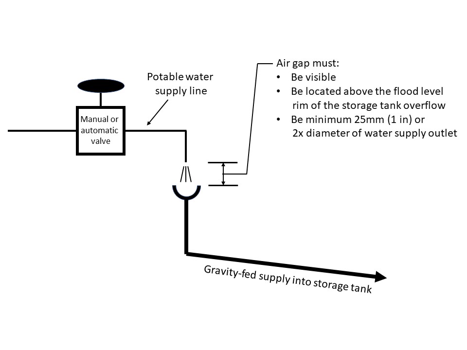
This physical break prevents the backflow of water since, even if rainwater backed up from the tank to the gap, it would spill from the gap and not encounter the potable water supply. The air gap must be located higher than the overflow drainage piping from the tank and the overflow drainage piping must remain free of blockage so that excess rainwater flows to the overflow system and does not back up and overflow at the air gap. The piping from the air gap to the tank must be sized large enough to allow the quantity of water that is exiting the pressurized outlet to be able to flow by gravity to the tank without backing up and spilling. The air gap must never be concealed and must be installed where occasional spitting from the air gap will not cause problems. The air gap is also never allowed to be bypassed by connecting a hose or extending the outlet below the flood level rim of the funnel.
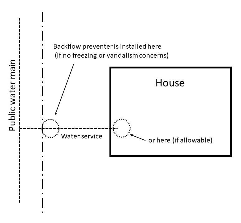
Premise protection
In addition to the installation of an air gap for zone isolation, a backflow preventer is also required on the water service to the building if a RWH system is proposed or in existence. This is known as “premise protection” or “premise isolation”. Premise protection assures that the public potable water system is protected from backflow that might occur through the water service. A backflow preventer, as specified by the AHJ, is installed on the water service either at the property line or immediately inside the building, to ensure that it is protected from vandalism and freezing, as well as to prevent being bypassed.
Manual and Automatic Top-up Systems
Potable water can be admitted to the storage tank either manually or automatically to keep enough water in the tank for proper operation of toilets and irrigation systems. Below are some advantages and disadvantages of each type.
| Make-up Water Method | Advantages | Disadvantages |
|---|---|---|
| Mobile Top-up |
|
|
| Automatic Top-up |
|
|
For most residential applications, it is recommended that the automatic top-up be selected as it minimizes service interruptions and is the least onerous for the homeowner.
A simplified diagram of the control strategy for an automatic top-up system is depicted in the graphic below.
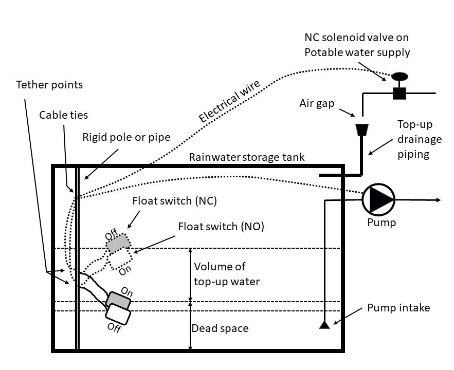
A brief description of control components for both manual and automatic systems is listed below. Some of these are not shown in the previous diagram.
- Water level sensor: mounted inside the tank, they indicate the water level in the tank. Like those found in an RV water or waste tank, their reaction to the liquid level sends an electrical signal to a control board causing LEDs to light, which in turn indicates that the tank is empty, ¼ full, ½ full, etc. Sensors can also be used to operate pumps if desired.
- Float switch: a small buoyant cylinder that tips up or down (inverts) depending on the liquid level. These devices are the same as those used to control a pump in a sump. They must always be made to tip rather than float horizontally. To achieve this. they can either have a lead weight fixed to the cord approximately 6 inches from the float, or the cord can be tethered to a fixed point. Float switches are either of the N.O. (normally open) or N.C. (normally closed) variety. A NC float switch can de-energize the pump if it opens, indicating that there is not enough water in the tank and preventing the pump from running dry. A N.O. switch can be used to allow the pump to run if it tips upward to close, indicating there is enough water for the pump to operate.
- Manual shutoff valves: used to manually control make-up water to the tank. They are normally left open if a solenoid valve downstream is used to add water to the tank. These are typically ball valves but can be of the gate or globe variety as desired. These are usually installed wherever isolation of water-operated components is necessary.
- Solenoid valve: a normally closed electrically operated valve that is used to automatically add potable make-up water to the tank when it reaches a critical level (dead space) and close when water reaches the “pump off” level as determined by the positioning of the float switches.
- Pump: these can either be mounted inside the tank (submersible) or outside the tank (jet-type). Regardless of the type used, the pump intake point must be set at 4” – 6” (100 mm – 150 mm) above the tank bottom to prevent any accumulated silt or debris from being pulled into it. Check valves must be installed on the intake pipe to prevent the pump from losing its “prime” (allowing water to fall back into the tank when the pump shuts off).
- Foot valve: a combination check valve/strainer used at the intake point of a jet pump to keep the pump primed with water when shut off, and to prevent debris from entering the intake piping.
Operation of the Make-up Water System
When stored rainwater reaches a low level in the cistern, a control device, such as a float switch or water level sensor, activates a top-up system to replenish the rainwater system with enough water to continue functioning properly. A solenoid valve opens to allow pressurized municipal potable water to discharge through an air gap into a funnel. The funnel and piping downstream of it are sized and sloped to allow gravity to carry the water into the tank. This continues until the desired water level in the cistern is reached, whereby the solenoid valve is de-energized, and the municipal water flow shuts off. The make-up water simply replenishes the cistern water level with enough water so that the rainwater harvesting system output continues to function normally.
Routine maintenance
If the make-up system is operating properly, it is recommended that it still be inspected once every six months to:
- verify that the float switch wires are not tangled with other float switches, the pump, or other objects in the tank
- remove any dirt and/or debris that have accumulated on the float switches, as necessary
- observe the make-up system while operating to ensure that water is not overflowing from the top-up drainage pipe at the air gap or discharging from the backflow preventers. If any water is leaking or discharging, identify the cause and correct.
While inspecting, cleaning or repairing the make-up system, follow all necessary safety precautions, such as disconnecting the power supply, when necessary. A qualified electrical contractor should be engaged for installation and repair of any electrical equipment.
Now complete Self-Test 5 and check your answers.
Self-Test 5
Self-Test 5
- What is the strategy known as whereby potable water is added to the cistern to prevent the pump from running dry in times of little or no rainfall?
- Top-up
- Make-up
- Bypassing
- Bolstering
- What is the primary concern regarding the question above?
- Creating a cross connection
- The need for extra piping and cost
- Depleting the potable water supply
- Finding a suitable contractor for the work
- Which one of the following options is the only one allowable by the plumbing codes to ensure there is enough water for use in a RWH system during periods of insufficient rainfall?
- Top-up
- Make-up
- Bypassing
- Bolstering
- What would the use of an air gap in a top-up system be considered?
- Unacceptable
- Not necessary
- Zone isolation
- Premise protection
- Which one of the following choices protects the building occupants from the effects of a potential cross connection?
- Zone isolation
- Building isolation
- Premise protection
- Occupant protection
- Which one of the following choices would not be a consideration for the installation of a backflow preventer on a water service at the property line?
- Freezing
- Aesthetics
- Vandalism
- Being bypassed
- Which one of the following choices is commonly used to operate a pump in a rainwater cistern?
- An air gap
- A float switch
- A pump intake
- A solenoid valve
- Which one of the following components of a RWH storage system is normally used to automatically add municipal water to the cistern?
- A foot valve
- A glove valve
- A solenoid valve
- A manual shutoff valve
- Where is the air gap for a make-up water system located?
- Between the solenoid valve and the cistern
- Between the cistern and the overflow piping
- Between the first-flush diverter and the cistern
- Between the roof catchment area and the solenoid valve
- In a make-up water system, when does the solenoid valve close?
- When the cistern water level spills into the overflow
- When the manual water fill valve has been turned off by the homeowner
- When a sensor or float switch is activated at the lowest water level desired
- When a sensor or float switch is activated at the highest water level desired
Check your answers using the Self-Test Answer Keys in Appendix 1.
Section 5: Pumps and Pressurized Distribution
Pressurized Distribution Systems
Pressurized water to toilets and irrigation systems is rarely gravity-fed, therefore pumps are needed to take water from the storage tank (cistern), pressurize it and deliver it to permitted fixtures which may be located several stories above. The system is composed of a pump, a pressure tank to store pressurized water, a pressure switch or constant pressure components, possible post-storage treatment devices, and plumbing lines that are clearly marked and kept separated from the potable system.
To ensure the proper operation of these systems, care must be taken when selecting the type and size of the pump, pressure tank, and associated equipment. The pressure system must be capable of supplying water at a sufficient rate and pressure to all the fixtures it is connected to, especially those located the highest and furthest away from the pump. Most importantly, it must be designed and installed to minimize the risk of a cross-connection and potential backflow.
Homeowner maintenance is also critical, as homeowners must periodically inspect the system and be capable of troubleshooting any issues should they arise.
General Operation and Equipment Selection
The pump and pressurized distribution system is composed of a series of interconnected components, located both inside the rainwater tank and inside the building. A typical pressure system for a rainwater tank in a below-ground application is shown below.
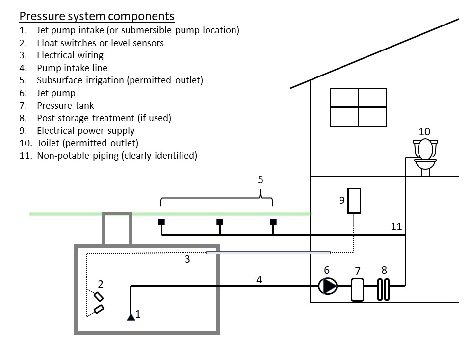
System operation
In the figure shown above, rainwater is pushed from the storage tank by a submersible pump located directly inside the tank or drawn from the tank by a jet pump located inside the building. The rainwater is moved through the intake line to a suitable location in the building, such as a mechanical room or basement utility room. Water level sensors, such as the float switches shown, are often used to protect the pump from running dry. The electrical wiring from the water level sensor(s) and pump (if applicable) are run through a watertight protective electrical supply conduit to an electrical supply panel. The panel supplies power and control for the pump operation.
Inside the building, the pump discharge is connected to a pressure tank with a pressure switch. The air charge in the tank provides pressure for the system piping so that the pump does not have to come on every time water is pushed through the piping. If the RWH system utilizes post-storage treatment units, these are installed downstream of the pump and pressure tank. The distribution piping then feeds the permitted fixtures, which are toilets and subsurface irrigation outlets only.
All piping for a RWH system must conform to the applicable sections of the plumbing code for factors such as pipe type, use, identification, and prohibited locations. Likely the most important feature of the distribution piping is that it must be clearly identified, either by labeling, tagging, or other easily identifiable means, as carrying non-potable water. Signs with statements such as “Danger! Non-potable water! Do not drink!” are expected to be posted in as many visible locations as possible, and either painting the piping or having the labeling display the colour purple is a universally known identifier for this purpose. Proper identification helps prevent unintended cross connections.
Pump selection
To select the appropriate pump for a given RWH system, criteria must be considered such as:
- pump location, controller configuration and voltage
- pump flow rate (l/sec or GPM)
- pump system head (pressure)
- acceptability of service interruptions
Pump location, controller configuration and voltage
Either a submersible pump located inside the tank, or a jet pump located outside the tank in an indoor/enclosed location may be used. Other types of exterior pumps are available as an alternative to jet pumps, such as vertical multi-stage pumps, however these are generally more suited to multi-residential and commercial applications. For most homeowners, the use of a jet pump located in the basement is preferred due to its accessibility, although maintaining prime can be an issue. Submersible pumps, although better suited for priming purposes, aren’t seen by homeowners as an easily accessible option.
Pumps for RWH systems are normally operated at line voltage, which can be either 120 or 240 VAC (volts alternating current). Controllers for pumps are normally pressure switches that are located on the piping at the pressure tank. These can also be operated at line voltage. If water sensors located in the cistern are meant to control the pump operation but are not of the line voltage type, there will need to be a relay or contactor wired into the circuit, allowing the sensors to operate on low voltage (e.g., 24 VAC) while still controlling the line voltage pump.
Pump Flow Rate
The amount of flow that must be generated by the pump depends on the type and number of fixtures connected to the distribution system. One method of determining this flow rate is to sum up the required flow rates of all the fixtures, assuming a “worst case” scenario where all fixtures are operating at one time. This approach is not recommended, however, as it tends to over-size the pump, increasing the cost of the pump and pressure system. Instead, it is recommended that the pump flow rate be sized to handle a portion of this maximum flow, such as the ability to supply two toilets simultaneously. The irrigation system can be operated by a timer so that it isn’t needing water through the times of day when the toilets are being used. Both subsurface irrigation and toilet operation require fairly low flow rates.
Pump Head
Once the flow rate has been determined, the next task is to calculate the amount of pressure, or “head” the pump must provide. Two factors must be considered:
- Required system pressure: This is the pressure required by the fixtures to operate properly, and
- Total dynamic head (TDH): This is the loss in pressure (or “head loss”) that occurs when water is moved from a low elevation to a higher elevation (elevation loss), and the loss that occurs when water is being moved through a system of pipes and fittings (friction loss).
Total dynamic head has three components, which are:
- Suction head: the vertical distance or height that water must be lifted (pulled) before arriving at the pump (this only applies to systems utilizing a jet pump)
- Discharge head: the vertical height from the pump to the highest fixture, and
- Friction head: the loss in pressure resulting from water traveling through pipes and fittings
As learned through earlier levels of training, static (at rest) water pressure can easily be calculated by measuring the height differences that the water must overcome between two points. A head pressure of 0.433 psi is created or lost for every 1 foot of vertical height. This can also be expressed as 9.8 kPa for every 1m of height.
The friction head encountered is a little more difficult to establish. Pipe manufacturers publish head loss charts at varying flow rates for their products. Pipe types must be determined and chosen so that the appropriate head loss charts can be used to determine how much pressure will be lost through the piping at the estimated flow rate.
Once the total dynamic head is determined, it is added to the required system pressure to arrive at the total head that the pump must produce. The pump chosen must be capable of providing at least this amount of head pressure.
Choosing the pump
Once both the pump head and the flow rate are determined, a pump can be selected, using pump literature, or “curves” provided by manufacturers. Pumps must be capable of supplying at least the pressure and flow rate that the system needs. As well, slightly oversizing the pump in both pressure and flow rate is suggested if there is a possibility of adding piping and fixtures to the system at a later date.
Pumps can be either constant speed or variable speed. There are advantages and disadvantages to both as are indicated below.
Constant speed pump
Advantages: generally, less expensive than VSD/VFD pumps; ideal for applications where minor variations in water pressure and flow rate are acceptable (for example, refilling toilet tanks after flushing and operating a garden hose); easiest for homeowners to understand and troubleshoot.
Disadvantages: pressure tanks can be quite large for applications requiring high flow rates; flow rate and system pressure may spike when pump activates, and pressure may drop if water demand is too high.
Variable speed drive/variable frequency drive pump
Advantages: provides constant pressure to fixtures, regardless of flow rate; uses very small pressure tanks, or a micro-pressure tank inside the pump or control unit; often has built in low/high voltage shut-off and dry run protection; smaller space requirements in the building; lower electricity consumption than comparable constant speed pumps.
Disadvantages: use of smaller pressure tanks requires a greater number of “pump starts”, potentially increasing pump wear; more expensive than constant speed pump systems; more difficult for homeowners to understand and troubleshoot.
Acceptability of Service Interruptions
A final issue to be considered when choosing a pump is whether it is acceptable for the non-potable water system to be interrupted by pump downtime or other potential problems associated with the RWH system. In a typical residential setting, where rainwater is used for toilet flushing and sub-surface irrigation, infrequent service interruptions are likely to be generally acceptable, and no added measures are necessary.
For multi-residential or commercial settings where water is needed for toilet and urinal flushing, service interruptions may not be as acceptable. For such settings, two options are available:
- A dual-pump arrangement, often referred to as a “duplex” pump setup, or
- An automatic bypass system. (Note that any interconnection between potable and non-potable water is prohibited by plumbing codes, so this option would only be acceptable if the auxiliary supply (RWH system) has been checked and certified as an “approved auxiliary supply” (potable) by the water purveyor. In a residential scenario, this is not a likely option).
A drawback of duplex pump arrangements is that they tend to be much more expensive than single-pump systems; however, many offer control equipment to periodically cycle or alternate the operation of the two pumps, which improves the lifespan of both. Another advantage of duplex pump arrangements is that they can often be purchased pre-assembled and installed in much the same manner as a typical single-pump arrangement.
The above are all valid considerations, with the system’s owner ultimately having the final determination as to pump selection.
Pressure tanks
Pressure tanks perform two functions in a pressurized RWH distribution system:
- They store water under pressure to minimize pump on/off cycling frequency; and
- They maintain a constant pressure in the distribution system.
Pressure tanks are composed of an exterior shell of either steel or fiberglass, with an inner RWH water-filled bladder surrounded by pressurized air. A pressure switch is mounted on the distribution piping at the pressure tank. The pump starts when the pressure in the distribution system piping drops to the “cut-in” point and shuts off when the pressure reaches the “cut-out” point. Depending on the style of switch chosen, these points are adjustable in their “differential (difference in PSI or kPa between cut-in and cut-out) and their approximate operating pressures (“range”). A pressure range, including cut-in and cut-out, is selected based on the sums of required pressure at the top of the system, elevation pressure loss and dynamic friction pressure loss as well as by the suggested operating pressure needed by the fixtures.
Other than the pressure switch settings, the most important factor in ensuring proper operation of the pressure system is sizing the pressure tank so that it is compatible with the type of pump and the pump’s flow rate.
Most inexpensive pumps operate at constant speeds; in other words, they are either on or off. Constant speed pumps require larger pressure tanks than a variable speed variety as they are designed to store the volume of water discharged by the pump over a 1–2-minute period. This is the minimum time the pump is suggested by manufacturers to operate once activated and is referred to as “pump run time”. A longer pump run time requires a larger pressure tank but minimizes wear due to frequent pump starts.
A tank for a variable speed drive/variable frequency drive pump need not be as large in volume as one for a constant speed pump. The controls and operation are different as well, so it is important to make sure that the pressure tank is matched to the pump.
Distribution piping
All piping located on private property must conform to requirements of the governing codes and bylaws, although the piping feeding out from outside of the house to the subsurface irrigation system can be as determined by the needs of the irrigation components.
A key component of the rainwater harvesting system consists of the dedicated non-potable plumbing lines that comply with CAN/CSA B128.1-06 which states:
All installed pipes are required to be purple in colour, distinguishing them from potable water lines. To prevent cross-connection, they must be separated from potable water lines by 100 mm (4 inches) for above-grade, and 300 mm (12 inches) for below-grade installations. All end use appliances plumbed with purple pipe must be clearly marked with a non-potable warning label such as shown below.

Colouring and labeling prevent misuse of the water as well as helping to avoid cross connections. Section 2.7 of the plumbing codes states the locations where the installation of non-potable pipe is prohibited, such as above food-handling equipment.
Now complete Self-Test 6 and check your answers
Self-Test 6
Self-Test 6
- Which one of the following components, located in the basement of a home, draws water from the cistern and pressurizes it?
- A jet pump
- A foot valve
- A pressure tank
- A submersible pump
- What is likely the most important consideration of the RWH system’s distribution piping?
- That it is sized correctly
- That it is clearly identified
- That it is protected from damage
- That it conforms to code requirements
- Pumps used in RWH systems are normally of what voltage value(s)?
- 208/240 VAC
- 120/240 VAC
- 24/120 VAC
- 12/24 VAC
- What would be required if a 24 VAC sensor was expected to turn on a 120 VAC pump?
- An amperage sensor
- A pressure switch
- A float switch
- A relay
- What piece of equipment is installed to ensure that the pipe sizing doesn’t have to allow for enough flow for the toilets and sub-irrigation system to operate simultaneously?
- A timer
- A bypass valve
- A manual valve
- A top-up make-up valve
- Which one of the following choices would not be a consideration when sizing a submersible pump for a RWH pressure system?
- Suction head
- Elevation head
- Discharge head
- Total dynamic head
- What type of pump is likely the most expensive, hardest for a homeowner to understand the operation of, and is therefore least likely to be chosen for a residential RWH system?
- A jet pump
- A constant speed pump
- A submersible pump
- A variable speed drive pump
- What is the minimum suggested “run time” for a pump, as determined by manufacturers?
- 15 to 30 sec
- 30 sec to 1 min
- 1 to 2 min
- 2 to 5 min
- What is the mandated colour scheme for any piping or equipment that conveys non-potable water?
- Red
- Blue
- Green
- Purple
- How much physical separation must be maintained between buried potable and non-potable pipes?
- At least 100 mm (4 inches)
- At least 300 mm (12 inches)
- No more than 6 inches (150 mm)
- No more than 8 inches (200 mm)
Check your answers using the Self-Test Answer Keys in Appendix 1.
Section 6: Overflow Provisions and Stormwater Management
In the event of an undersized cistern or excessive rainfall to the catchment area, the cistern may overflow. This can cause undesirable situations such as the conveyance piping backing up and spilling rainwater against the building, damaging the building’s exterior and/or interior. The excessive flow from the tank’s overflow piping could also negatively impact the surroundings. All rainwater harvesting systems must incorporate a suitable and permissible overflow discharge system to adequately distribute rainwater that can no longer fit within the cistern. Overflow system sizing must take into account the size of the conveyance piping entering the cistern, as well as other considerations such as whether the discharge is by gravity or by pump, potential landscaping issues, allowable tie-in to a municipal storm system, and other identifiable site constraints.
“Stormwater management” is the practice of collecting and disposing of stormwater so that soil erosion and flooding on private and public property are minimized or avoided. Stormwater management has evolved considerably over the past decades and has shifted from simply directing runoff from private property into off-site locations such as ditches and streams, to managing it through on-site practices and treatment facilities designed to mitigate its impacts. Because RWH systems are a relatively new addition to stormwater management practices in Canada, there is little guidance on how to integrate these systems into stormwater management programs. Despite lack of specific guidelines, many aspects of residential onsite stormwater management are directly applicable to RWH tank overflow handling.
Code Requirements
Few regulations exist that deal specifically with onsite stormwater management. The NPC cites clauses that address sizing, pipe type, slope, etc. of leaders, storm building drains and sewers to their point of connection at the property line but doesn’t address any types of on-site disposal. It does, however, prohibit the direct connection of an overflow from a rainwater tank to a storm sewer because of the possibility of storm sewage backing up into the rainwater tank during extreme rainfall events. CSA Standard B128.1 (2006) specifies that the capacity of the overflow drainage pipes from a RWH system must be equal to the capacity of the conveyance drainage pipes, and that overflows must be discharged in accordance with local regulations. Even if there are no special stormwater management requirements, provincial regulations and municipal bylaws may still restrict the locations where rainwater overflows can be discharged. Some municipalities may, however, accept such connections provided they are protected by a backwater valve. Alternatively, an indirect connection may be made, where the rainwater tank overflows into either a small inceptor tank or “soakaway pit”, which in turn overflows into the storm sewer.
This section will describe the most common ways of dealing with excess runoff from a RWH system.
Main factors that apply to the choice of an overflow discharge location
- Local stormwater management requirements: There may be special requirements enforced by the municipality. The home or building may be in an environmentally sensitive area, or the municipal stormwater system may not be able to handle extra stormwater flows. Connection to the public drainage system is subject to the AHJ as part of an overall stormwater management plan for the city or municipality.
- Applicable Provincial codes, regulations, and municipal bylaws: There may be restricted locations and methods of discharging overflows beyond those which are governed by the local AHJ. These must be satisfied along with, and not instead of, the local requirements.
- Location of the storage tank: Discharging overflow from below-grade tanks by gravity drainage is more complicated than discharging from above-grade tanks. Excess runoff can be pumped to its destination as well.
- Site conditions: Topography, available space and presence of buried service lines affect the overflow discharge location.
The options discussed below take into consideration the method of handling runoff (gravity or pumped) combined with the end destination for the overflow discharge (to grade, a storm sewer, or a soakaway pit).
Gravity drainage to grade
The easiest and most recommended method of overflow discharge is to gravity feed the overflow to grade and manage it within the homeowner’s property. Advantages of this method include simplicity, and a low probability of rainwater backing up the overflow drainage piping. Disadvantages include possible soil erosion, safety/nuisance hazards, and freezing/ice buildup if not designed properly. Gravity fed systems require significant elevation changes in the property to allow an above-or-below-grade tank’s overflow pipe to drain downhill and away from other structures.
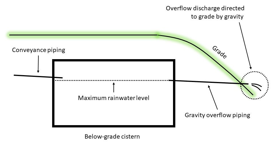
Pumped drainage to grade
This method is the least recommended. It is applicable to tanks located below ground or integrated into buildings, where the grade level is above the overflow. Used where grade elevations won’t allow for gravity overflow drainage, the most common method of discharging overflow from a below-grade cistern is to pump the excess water to grade with a dedicated overflow pump. The pumped overflow should be directed to a landscaping feature, such as a rain garden or stormwater retention pond where water eventually evaporates or percolates into the ground. Advantages of this method include minimal reliance on grade elevations and ability to move overflow water over greater distance to get to the final disposal location. Disadvantages include increased cost of installation and maintenance, proper pump sizing, and inability to move water during power outages. The grade downstream of the pumped outlet must be carefully constructed to minimize soil erosion.
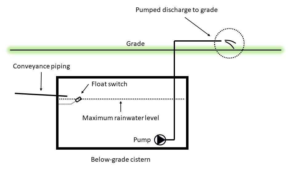
Gravity discharge to a storm sewer
If allowed, the rainwater tank overflow may be connected to a storm sewer but must be done in a way that prevents backflow of storm water into the RWH tank, such as by the installation of a backwater valve, as seen below. Advantages include frost protection, aesthetics (all overflow piping is below ground), and non-reliance on electrically powered pumps. Disadvantages include possible prohibitions or restricted allowances as determined by the AHJ, and possible storm water backups affecting the tank.
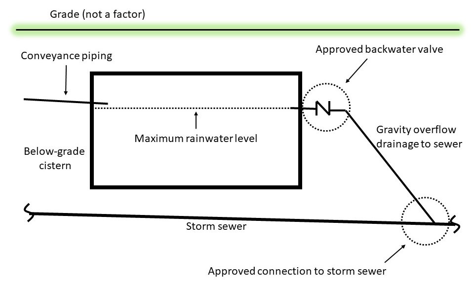
Pumped discharge to a storm sewer
In cases where the tank is located deep underground (building sub-basements, parking garages, etc.) this may be the only method of handling overflows and would be listed as an advantage. However, the disadvantages include the pump is subject to failing during power outages, and it must be sized to handle potentially large volumes of water during intense rainfall events. Again, the AHJ will be the determiner of the allowance to use this type of system.
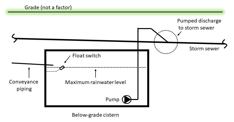
Gravity discharge to a soakaway pit
This method is applicable to situations where tanks are located below ground and rainwater must be kept onsite. A soakaway pit is simply a hole in the ground that is filled with rock of 2″ or larger aggregate. Advantages of soakaway pits include aesthetics, simple design and non-reliance on electrical power. Disadvantages are the need for large excavating and hauling equipment access, percolation rates of surrounding soils, and impact on the water table. Once again, the AHJ must be consulted before installing any soakaway pit.
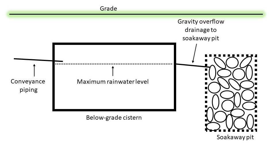
Selecting the Most Appropriate Overflow Discharge Location
Selection of an overflow discharge location must take several factors into account, which include but are not limited to:
- stormwater management requirements
- applicable provincial/territorial regulations and municipal bylaws
- location/placement of the rainwater storage tank, and
- site conditions.
Stormwater management requirements
In some cases, overflow from the rainwater tank may need to be handled in accordance with special stormwater management requirements. These requirements may be imposed by a municipality or various conservation authorities for buildings located in an environmentally sensitive area, or in an area where the existing storm sewer infrastructure does not have sufficient capacity to accept additional stormwater flows, or for a variety of other reasons. Stipulations may include on-site retention of certain storm volumes with specified rates of release to the storm sewer and/or on-site management through infiltration or overland flow. Local authorities, including local conservation authorities, should be consulted during the RWH system design process, to verify whether special stormwater management practices are required. A certified hydrologist may need to be consulted, especially if all runoff is to be retained on site.
Applicable provincial/territorial regulations and municipal bylaws
Even if there are no special stormwater management requirements, provincial regulations and municipal bylaws may still restrict the locations where rainwater overflows can be discharged. The National Plumbing Code prohibits the direct connection of an overflow from a rainwater tank to a storm sewer because of the possibility of storm sewage backing up into the rainwater tank during extreme rainfall events. Some municipalities may, however, accept such connections if they are protected by a backwater valve. Alternatively, an indirect connection may be made, where the rainwater tank overflows into either a small inceptor tank or soakaway pit, which in turn overflows into the storm sewer.
Tank location
The location of the storage tank can also have an impact on the overflow discharge location selected. Overflow handling is simplest with above-ground tanks since overflows can typically be discharged to grade. Handling overflows is more challenging with below-ground tanks and/or tanks integrated into buildings (located below grade). For these tanks, proximity to a storm sewer connection or to greenspace (for infiltration or overland flow) often plays a much greater role in determining where overflows can be directed.
Site conditions
Site conditions, such as topography, space availability and accessibility, and the existence of other buried services, also affect the selection of an overflow discharge location. For instance, a flat terrain may preclude the discharge of overflow from a buried tank to grade. Similarly, space constraints and buried service lines may limit excavation for overflow drainage piping and/or a soakaway pit.
Soakaway Pits
Soakaway pits, likely more commonly called drywells, are particularly sensitive to site conditions. In addition to requiring significant space, they also require a degree of soil permeability, that is, soil cannot have a significant clay content. Sites with a large catchment area and/or low soil permeability may require a large infiltration area and/or the soakaway pit itself may require an overflow. In some cases, soakaway pits may not be feasible.
Soakaway pits are composed of an excavated space filled with a non-porous material, such as stone, surrounded by an outer filter fabric. If the catchment area is very large and/or the soil is not sufficiently permeable, the soakaway pit may require its own overflow drainage pipe to a storm sewer or to grade. If treatment is required (e.g., if the soil is very permeable and the pit is to be located near a well), a sand layer may be installed at the bottom of the trench.
Now complete Self-Test 7 and check your answers.
Self-Test 7
Self-Test 7
- What is the practice of collecting and disposing of rainfall runoff in a responsible manner known as?
- Code compliance
- Stormwater disposal
- Responsible drainage
- Stormwater management
- The NPC prohibits the direct connection of a RWH overflow to a storm sewer system; however, it may be allowed by the AHJ provided there is what installed between the two systems?
- A three-way valve
- A backwater valve
- A first-flush diverter
- Pre-storage treatment
- Which one of the following is considered the easiest and most recommended option for a RWH system overflow?
- Gravity drainage to grade
- Pumped discharge to grade
- Gravity drainage to a storm sewer
- Pumped discharge to a storm sewer
- Which one of the following is considered the least recommended option?
- Gravity drainage to grade
- Pumped discharge to grade
- Gravity drainage to a storm sewer
- Pumped discharge to a storm sewer
- Which one of the options listed below may be the only method of handling overflow from a tank located in an underground parking garage?
- Gravity drainage to grade
- Pumped discharge to grade
- Gravity drainage to a storm sewer
- Pumped discharge to a storm sewer
- What is another term for a soakaway pit?
- A cistern
- A drywell
- A septic tank
- A septic field
- What type of soil listed below is least suitable for the use of a soakaway pit?
- Sand
- Rock
- Clay
- Loam
- What type of tank would make overflow handling easiest, but would encounter issues stemming from freezing and aesthetics?
- Above-grade
- Below-grade
- Semi-buried
- Integrated
- What may a soakaway pit require if the catchment area is very large and/or the the soil is not sufficiently permeable?
- An overflow
- More filter cloth
- Smaller aggregate
- A backwater valve
Check your answers using the Self-Test Answer Keys in Appendix 1.
Media Attributions
- Figure 1 Calculation of roof area catchment volume by John Gordon is licensed under a CC BY-NC-SA licence.
- Figure 2 Typical residential conveyance network by John Gordon is licensed under a CC BY-NC-SA licence.
- Figure 3 Typical rainwater storage tank by Camosun College is licensed under a CC BY 4.0 licence.
- Figure 4 Operation of “first-flush” diverter by John Gordon is licensed under a CC BY-NC-SA licence.
- Figure 5a Pre-storage filtration devices by India Water Portal is licensed under a CC BY-NC-SA 2.0 licence.
- Figure 5b Gutter guard by Stilfehler is licensed under a CC BY-SA licence.
- Figure 5c Gutter guard by 123switch is licensed under a Pixabay License.
- Figure 6 Rainwater storage tank with settling and storage chambers by ITA is licensed under a CC BY-NC-SA licence.
- Figure 7 Air gap as zone isolation for make-up water by Greg Wirachowsky is licensed under a CC BY-NC-SA licence.
- Figure 8 Premise protection by Greg Wirachowsky is licensed under a CC BY-NC-SA licence.
- Figure 9 Automatic top-up system by Greg Wirachowsky is licensed under a CC BY-NC-SA licence.
- Figure 10 RWH pressure distribution system by Greg Wirachowsky is licensed under a CC BY-NC-SA licence.
- Figure 11 Example of warning label for non-potable water systems by Greg Wirachowsky is licensed under a CC BY-NC-SA licence.
- Figure 12 To grade by gravity by Greg Wirachowsky is licensed under a CC BY-NC-SA licence.
- Figure 13 To grade by pump by Greg Wirachowsky is licensed under a CC BY-NC-SA licence.
- Figure 14 To sewer by gravity by Greg Wirachowsky is licensed under a CC BY-NC-SA licence.
- Figure 15 To sewer by pump by Greg Wirachowsky is licensed under a CC BY-NC-SA licence.
- Figure 16 To soakaway pit by gravity by Greg Wirachowsky is licensed under a CC BY-NC-SA licence.
