Learning Task 1
Describe Water Services
Building Codes require that every dwelling unit shall be supplied with potable water. The water supply system that supplies the potable water can be provided by public or private water supplies, and the source can be from above ground water such as lakes and rivers, or it can come from underground aquifers that are accessed through wells. Once a water supply has been established, a distribution system that will ensure a safe and adequate delivery of potable water must be designed and installed.
For the purposes of the content in this section, the term “water services” will be interpreted as the water supply system upstream of the curb stop. This part of the water supply system is often referred to as the municipal water supply system if the water source is public.
Many of the terms used to describe water supply systems are defined below.
Terminology
As with all trade-specific content, an understanding of the related terms is important before covering the content in detail. The terms defined below are used to describe water supply systems and the associated components and equipment. The list of terms is specific to British Columbia, but most will have a similar meaning in other regions of Canada.
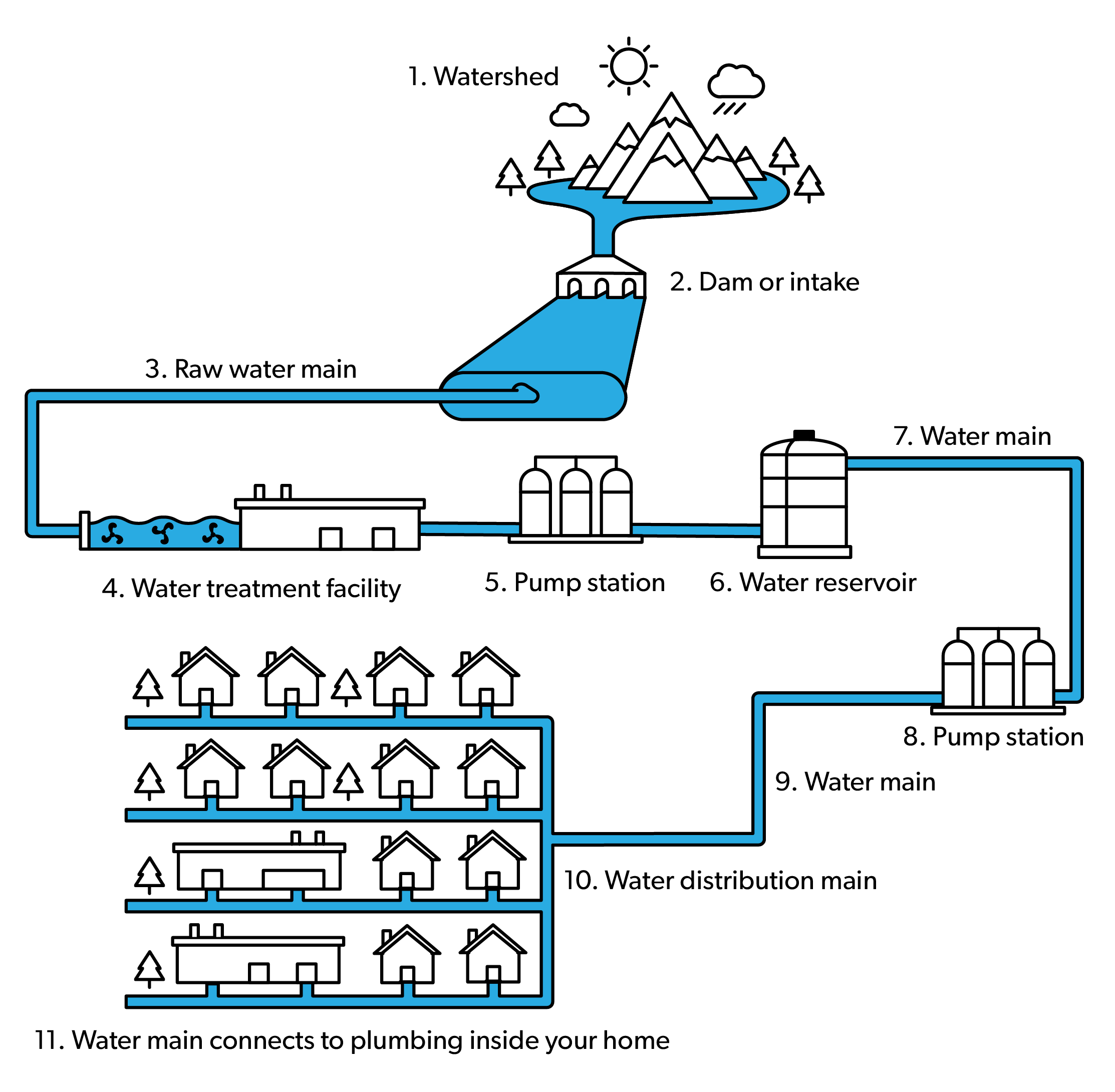
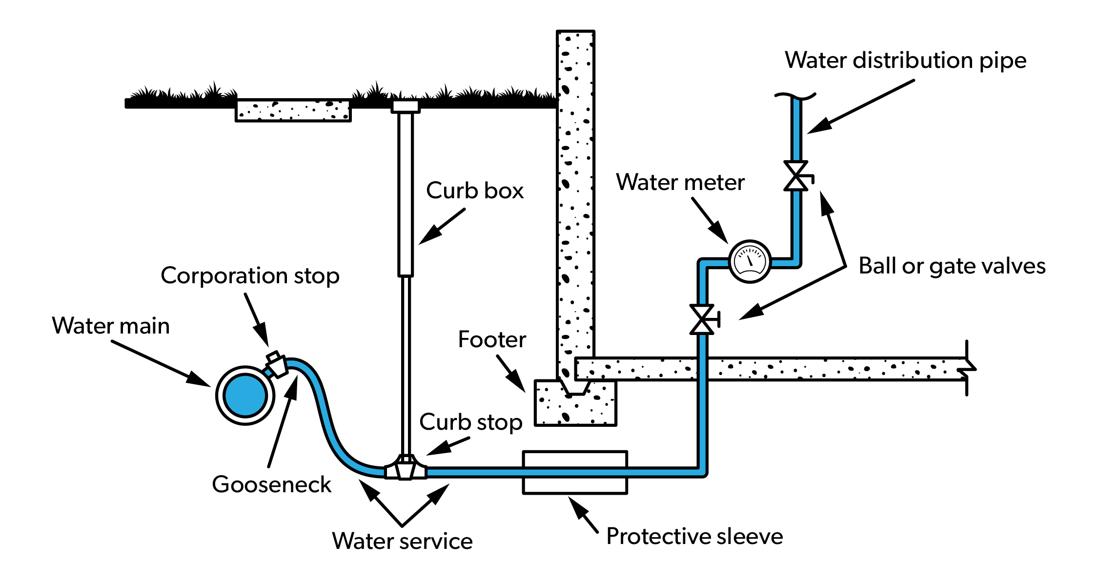
An example of a complete system, from source to tap, is shown in Figure 1 and can be used to identify different parts of the water supply system.
Building Water Distribution System
The BC Plumbing Code (BCPC) defines the term “water distribution system” as an assembly of pipes, fittings, valves and appurtenances that conveys water from the water service pipe or private water supply system to water supply outlets, fixtures, appliances and devices. Although the BC Plumbing Code implies that a water distribution system is the piping and components downstream of the curb stop, the term “distribution system” also gets used to describe parts of the municipal water supply system that is upstream of the curb stop. For the purposes of this competency, the term “building water distribution system” will be used to define the water distribution system inside the building.
Building Water Supply System
This term is used to differentiate the water distribution system downstream of the curb stop from the system upstream of the curb stop. The term comprises the water service pipe and the building water distribution system. Plumbers are involved in the design and installation of this part of the system.
Contaminated Water
Contaminated water is water that contains matter that is capable of seriously affecting the health of people drinking the water. Contaminants may be organic or inorganic in origin.
Corporation Stop
A valve installed on a municipal water main to permit joining of the water service pipe.
Cross Connection
A cross connection is an existing connection or a potential connection between any part of a potable water system and any other environment containing any other substances in a manner which, under any circumstances, would allow such substance to enter the potable water system.
Another way to define a cross connection is any actual or potential connection between the waterworks and any source of pollution, contamination or other material or substance that could change the quality of water in a drinking water supply.
Curb Stop
The curb stop is the valve installed on a water service to turn the flow of potable water to a building on or off.
Domestic Purposes
This term means the use of water for human consumption, food preparation or sanitation.
Municipal Water Distribution System
This term is used to define the part of the water supply system upstream of the curb stop, and includes piping commonly referred to as the water main. Plumbers are not generally involved in the design of this part of the system but may install and maintain the piping and components that make up the system.
Polluted Water
Polluted water is water that contains objectionable matter that will not injure the health of humans drinking the water. Pollutants may be organic or inorganic in origin.
Potable Water
The BC Drinking Water Act defines potable water as water provided by a domestic water system that meets the prescribed standard(s), and is safe to drink and fit for domestic purposes without further treatment. Essentially, potable water is water that is safe for human consumption.
Pressure System
A pressure system is a water supply design that uses equipment and components that include pumps, pressure tanks, and controls. Types of pressure systems include shallow well, deep well, and boosted systems.
Private Water Supply System
The BC Plumbing Code defines this term as an assembly of pipes, fittings, valves, equipment and appurtenances that supplies water from a private source to a water distribution system. The term “rural water supply” is sometimes used interchangeably with private water supply system. Both terms refer to systems that generally incorporate pressure systems.
Raw Water
Raw water is water in its natural state, like rainwater, groundwater, and water from bodies like lakes and rivers. Water is considered to be raw until it is treated by a potable water treatment process.
Riser
The BC Plumbing Code defines riser as a water distribution pipe that extends through at least one full storey of a building. A riser is part of a building water distribution system
Used Water
Any water supplied by a water purveyor from a public potable water system to a consumer’s water system after it has passed through the service connection and is no longer under the control of the water purveyor.
Water Distribution System
The BC Plumbing Code defines this term as an assembly of pipes, fittings, valves and appurtenances that conveys water from the water service pipe or private water supply system to water supply outlets, fixtures, appliances and devices. Although the BC Plumbing Code implies that a water distribution system is the piping and components downstream of the curb stop, the term “distribution system” also gets used to describe parts of the municipal water supply system that is upstream of the curb stop. For the purposes of this competency the term “municipal water distribution system” will be used to describe part of the system that is upstream of the curb stop.
Water Mains
Water mains are part of the municipal water distribution system. These large pipes are used to deliver potable water from the purveyor’s source to the water service pipe. Usually these are underground pipes operating at higher pressures than required by the end user. This term also gets used as a catch-all term to describe the entire water supply system upstream of the curb stop.
Water Purveyor
A purveyor is the owner or operator of a potable waterworks system. A water purveyor is also referred to as a water provider or water supplier. A water purveyor can be a private for-profit entity, or public not-for-profit entity. Purveyors can be a water wholesaler, selling potable water to municipalities for resale to their customers, or a retailer, directly selling to the end-user.
Water Service Pipe
The BC Plumbing Code defines this term as a pipe that conveys water from a public water main or private water source to the inside of the building.
Water Supply System
This term is used to describe the entire system of pipes, fittings, valves, and appurtenances that supply potable water from the source to the tap. For the purposes of this content the water supply system can be divided into the system upstream of the curb stop, referred to as the municipal water supply system, and the system downstream of the curb stop, referred to as the building water supply system.
Water System
The BC Plumbing Code defines this term as a private water supply system, a water service pipe, a water distribution system or parts thereof.
The Water Supply System
In British Columbia, over 90% of residents get their water from municipal water supply systems, while the remainder get their water from private wells, with a small percentage getting their water delivered by tanker trucks into holding tanks.
Most of the raw water that feeds into municipal water supply systems comes from rivers and lakes, referred to as surface water sources. Municipal water supply systems can also get raw water from underground aquifers, referred to as ground water sources. In municipal water supply systems, the raw water is treated before it is pumped to homes and businesses. The quality of the raw source water determines the type of treatment method required.
After treatment, municipal water supply systems distribute water to homes and businesses in large pipes called water mains that are usually buried under roads and sidewalks. Water mains are maintained by the purveyor, and paid for by water rates and property taxes.
Water service pipes and building water distribution systems are smaller pipes that transport the water from water mains to individual homes, apartments and businesses.
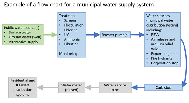
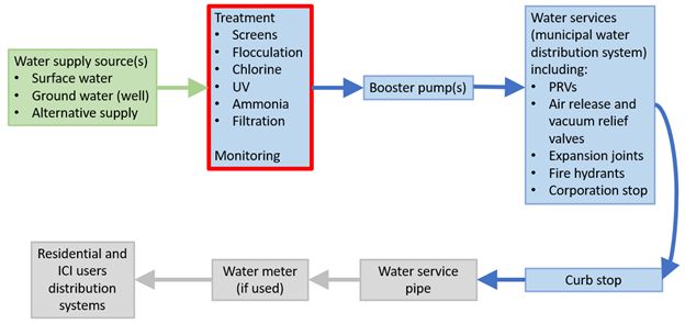
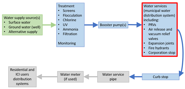
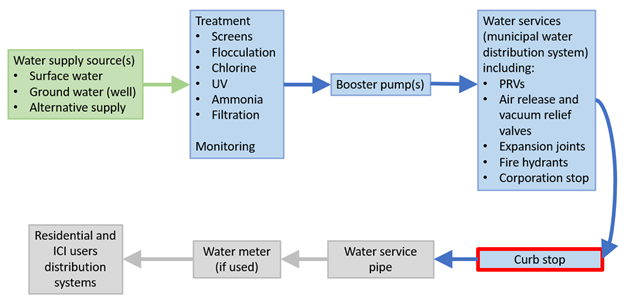
Figure 2 shows the water supply system, from source to tap, separated into different sections. Each section will be covered in the content below.
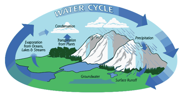
The Water Cycle
Without water, there would be no life on Earth. Earth and its atmosphere comprise a closed system where no new water is introduced; rather, the water that exists on earth today is the same water that existed billions of years ago. The journey water takes to your tap begins with a source that is supplied by the water cycle. The water cycle, or hydrologic cycle, is the path water takes as it moves through the environment. It is a natural recycling system that cleans water and allows it to be endlessly reused.
The water cycle is a complex system that includes many different processes. Liquid water evaporates from oceans, lakes, and streams into water vapor, condenses to form clouds, and precipitates back to earth in the form of rain and snow. Water in different phases moves through the atmosphere. Liquid water flows across land as surface runoff, and into the ground by infiltration and percolation. Groundwater moves into plants (plant uptake) and evaporates from plants into the atmosphere through a process called transpiration. Solid ice and snow can turn directly into gas (sublimation). The opposite can also take place when water vapor becomes solid (deposition).
Although water that has been evaporated starts out as pure water, pollution and contamination can quickly occur. Water stored in clouds absorbs carbon dioxide from the atmosphere and precipitation may collect other impurities from the atmosphere as it falls to earth. Absorbed carbon dioxide lowers the pH of water below neutral. The more carbon dioxide absorbed, the lower the pH level will be. Other atmospheric impurities, such as nitrogen oxides and sulphur, also lower the pH level of precipitation. If the pH level is less than 7, the water is considered to be acidic. The pH level of natural precipitation is commonly close to 5.6, but lower levels have been reported, particularly downwind from large cities or industrial developments. At pH levels over 7, water is considered to be alkaline. The pH level of precipitation is rarely above 7, but higher levels have been observed, primarily downwind from industrial areas generating alkaline pollutants.
When precipitation falls to earth, its increased carbon dioxide content boosts its capability to dissolve mineral matter on which it falls. Water is called a universal solvent because more things can be dissolved by water than by any other liquid. The amount of mineral or chemical matter that water can dissolve depends on the pH level and temperature of the water, solubility of the substance it contacts and how long the water is in contact with the substance. These factors partially determine how potable or suitable for human consumption, the water is.
Each water source has its associated advantages and disadvantages. Primary considerations for a water source are:
- the quantity of water available,
- the continuity of supply from the source and
- the quality of water the source is able to provide.
Water Supply System Types
In British Columbia, a “water supply system” is defined as all the equipment, works and facilities used for treatment, diversion, storage, pumping, transmission and distribution for a system which serves more than a single-family residence.
The majority of Canada’s population is classified as urban, and the distribution of water to this group of users is a major task. Most of Canada’s larger cities are located on or near a major river system or lake, which can be used as a source for a public water supply system. If a public water supply system is not available, a private water supply, or alternative water supply, may be used as a drinking water source.
To help identify and describe common piping and components of a water supply system this Competency will use the figure below to break the system into sections. We will begin at the upstream end of the water supply system by defining the different types of systems.
Public water supply systems
Public systems are generally owned and operated by municipalities or specifically created utilities. The purveyor of public supply systems commonly uses reservoirs to ensure an adequate supply of water throughout the year and, if necessary, treatment and testing systems are in place to ensure the water quality meets provincial and national standards.
Modern public systems can be defined as being either small or large. In British Columbia a “small system” means a water supply system that serves up to 500 individuals during any 24-hour period. This means a “large system” would serve more than 500 individuals during any 24-hour period.
Publicly-owned municipal water supply systems must provide water for fire protection, and are sized based on pressure and flow at the period of peak demand.
Private water supply systems
A private water supply system is defined by the BC Plumbing Code as an assembly of pipes, fittings, valves, equipment and appurtenances that supplies water from a private source to a water distribution system. Since the term “water distribution system” essentially means the water piping inside the building, the term “private water supply system” is interpreted as meaning a water supply to be used only on the same property as the source.
There are many situations where a public water supply system may not be available, so in this case a property owner has the option to drill a private well and use groundwater, or use surface water such as lakes and streams, to supply domestic water for personal use. These residential systems are intended to be used only for supplying potable water to the single-family home (dwelling unit) on the property; sharing water with a neighbour, for instance, may not be permitted. If you have a good neighbour system and own the water source, you might be considered to be a water purveyor (provider) and specific responsibilities under the Drinking Water Protection Act may apply to you.
Residential systems are also referred to as rural systems or pressure systems. There are several types of these systems including shallow well, deep well, and boosted systems. These systems include components such as pressure tanks, pumps, and controls and are covered in more detail in the plumber Level 4 content.
Unlike a municipal water supply system, a private water supply system does not typically provide water for fire protection.
Private water utility
In British Columbia, there are private water utilities (purveyors) that source their water from private property. A private water utility under the Water Utility Act is a person/business who owns or operates equipment or facilities for the delivery of domestic water service to five (5) or more persons or to a corporation for compensation. Private water utilities are usually created by developers to serve rural land development where community water service is required for subdivision approval, and where there is no other water purveyor in the area that can provide service.
There are dozens of regulated private water utilities throughout British Columbia that provide water to customers who are not connected to a public system. The private water system purveyors must meet the same water quality standards as the public systems and, therefore many incorporate water treatment as part of their process.
Alternative green water supply systems
This content is covered in another Competency of the plumber Level 3 content.
Protecting the Water Supply
Health Canada states “the best way to make sure drinking water supplies are kept clean, safe and reliable is to take a preventive risk management approach. This means understanding each water supply from its beginning in nature to where it reaches the consumer.”
The multi-barrier approach to safe drinking water
As drinking water travels on its journey to the end user, it can become contaminated in many ways. The multi-barrier approach to managing drinking water supplies is a preventive risk management approach that identifies all known and potential hazards and makes sure barriers are in place to reduce or eliminate the risk of contamination.
The BC Plumbing Code addresses protecting a potable water system from contamination in Article 2.6.2.1. Connection of Systems:
- Except as provided in Sentence (2), connections to potable water systems shall be designed and installed so that non-potable water or substances that may render the water non-potable cannot enter the system.
- A water treatment device or apparatus shall not be installed unless it can be demonstrated that the device or apparatus will not introduce substances into the system that may endanger health.
Cross connection devices
Cross connection control devices, such as back-siphonage preventers and backflow preventers, are found throughout public ad private domestic water systems. These devices help prevent “used water” from backflowing into the potable water supply system. “Used water” is any water supplied by a water purveyor from a public potable water system to a consumer’s water system after it has passed through the service connection and is no longer under the control of the water purveyor.
The source water is protected by the water supply system operator (purveyor), but the plumber may be required to determine the protection required for the treatment equipment and building water distribution system. Because of the liability associated with selecting the correct level of protection for cross connection control, plumbers are more likely to install and service cross connection devices than to actually select them.
The BC Plumbing Code lists most of the back-siphonage and backflow preventers used by plumbers in Article 2.2.10.10.
Cross connection control devices are covered in detail in Block C section of the plumber Level 3 content.
Water Treatment and Monitoring
Moving downstream, the next section of the municipal water supply system to be covered is Treatment and Monitoring.
Water purveyors rely on the water cycle to provide high quality raw water as a starting point for their potable water supply systems. Depending on the initial water quality, some form of water treatment may be required. The potable water delivered to the end user must meet the applicable water quality standards set out by the authority having jurisdiction (AHJ).
Almost all domestic water goes through some form of treatment before being delivered to the end user. In British Columbia, water suppliers are responsible for delivering safe drinking water that meets the requirements of the Drinking Water Protection Act and Drinking Water Protection Regulation, as well as the conditions set on their operating permits. These requirements include treating the water, if necessary, and ensuring water quality through monitoring. Water suppliers must notify the public when there is a potential or actual problem.
Most public water supply systems will include several stages of screens and filtration (to remove suspended particles, debris and algae) and disinfection (to remove bacteria and viruses). Disinfection methods include chlorination and treatment with ultra violet (UV) light. Water obtained from any source must not be considered potable (safe for human consumption) until the water has been properly tested for its mineral, chemical and biological characteristics and the results of the test compared to the Guidelines. Water is then piped into the transmission and distribution network and sent to homes, schools, and businesses for people to use.
The water purveyor carefully manages the supply and delivery of safe and sustainable drinking water. Delivering safe drinking water from source to tap includes protecting the source, disinfecting the water and monitoring water quality, operating and maintaining transmission and distribution systems, and investing in infrastructure renewal. Purveyors have strategic plans in place to ensure safe and sustainable drinking water well into the future.
Potable water from a public system is closely monitoring for water quality but if the water source is a private system that only supplies water to one connection then the responsibility for testing the water is up to the homeowner. The water treatment equipment used for single-family dwellings is covered in the Level 4 content of the plumber program. Plumbers will typically design the residential water treatment system and then complete the installation of the system, integrating it in with the building water distribution system.
Pumps
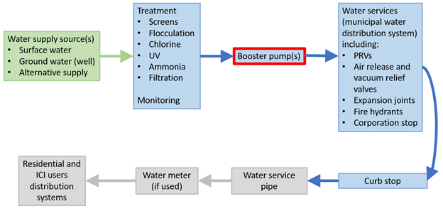
Moving downstream to the next section of the public water supply system will bring us to Booster pumps. Booster pumps are used throughout water supply systems but the content in this section is only an introduction to pumps in general. Booster pumps used on building water distribution systems will be covered in Competency B-2.
Note that pumps for private water supply systems are covered in greater detail in the plumber Level 4 content.
Ideally, a water supply system would rely only on head pressure to move the water from the source to the tap. This is almost never possible. A municipal water supply system will use pumps to move water in many different locations, including:
- Raw surface water from source to treatment plant
- Municipal wells to the treatment plant
- Water treatment plant processes
- Potable water to water towers
- Distribution system booster pumps
Modern pumps come in many designs and are used for an extraordinary range of applications. The focus of this section will be to describe the basic operation of different pumps and to introduce common pumps used by plumbers. Pump manufacturers and suppliers can be great resources for plumbers who are new to working with pumps. In all cases, the applicable documentation must be reviewed before selecting and installing any pump to ensure the selected unit will meet or exceed the system parameters.
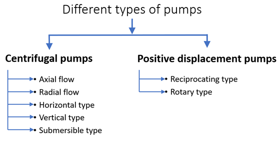
Classifying or categorizing pumps is complex so, for the purposes of this content, pumps will be categorized as two different types based on the operating principle. The categories are positive displacement and centrifugal, but there are many different design classifications within these categories.
Centrifugal Pump Design and Theory of Operation
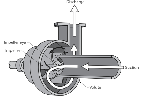
A centrifugal pump is a mechanical device designed to move a fluid by means of the transfer of rotational energy from one or more driven rotors, called impellers. Fluid enters the rapidly rotating impeller along its axis and is cast out by centrifugal force along its circumference through the impeller’s vane tips. The action of the impeller increases the fluid’s velocity and pressure and also directs it towards the pump outlet. The pump casing is specially designed to constrict the fluid from the pump inlet, direct it into the impeller and then slow and control the fluid before discharge.
The impeller is the key component of a centrifugal pump. It consists of a series of curved vanes. Fluid enters the impeller at its axis (the eye) and exits along the circumference between the vanes. The impeller, on the opposite side to the eye, is connected through a drive shaft to a motor and rotated at high speed. The rotational motion of the impeller accelerates the fluid out through the impeller vanes into the pump casing.
Figure 8 shows the names associated with a centrifugal pump, as well as the flow path through the impeller and casing.
Positive Displacement Pump Design and Theory of Operation
A positive displacement pump moves a fluid by repeatedly enclosing a fixed volume and moving it mechanically through the system. The pumping action is cyclic and can be driven by pistons, screws, gears, rollers, diaphragms or vanes. Although there are a wide variety of pump designs, the majority can be placed into two categories: reciprocating and rotary.
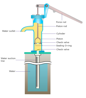
Reciprocating pumps
A reciprocating positive displacement pump works by the repeated back-and-forth movement (strokes) of either a piston, plunger or diaphragm. These cycles are called reciprocation. A simple hand pump that uses the reciprocating piston principle is shown below.
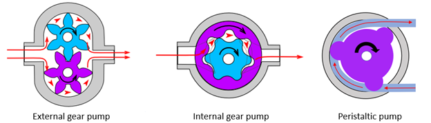
Rotary pumps
Rotary positive displacement pumps use the actions of rotating cogs or gears to transfer fluids, rather than the back-and-forth motion of reciprocating pumps. The rotating element develops a liquid seal with the pump casing and creates suction at the pump inlet. Fluid drawn into the pump is enclosed within the teeth of its rotating cogs or gears and transferred to the discharge. The simplest example of a rotary positive displacement pump is the gear pump. Examples of external gear, internal gear and a peristaltic rotary positive displacement pumps are shown below.
When selecting a pump for a specific application, the plumber chooses the type and design based on factors such as the outlet pressure required, the volume required to be delivered, the fluid being pumped, etc. Below is a description of some of the pumps commonly used by plumbers.
Booster pumps
These pumps are usually electrically driven, multi-stage, centrifugal pumps incorporating a non-return valve and are used when the water supply pressure is not high enough to operate fixtures and equipment downstream. Water purveyors use booster pumps to boost the water main pressure at different intervals based on pressure loss in the piping or elevation change within the system. Buildings such as high-rises may use booster pumps to ensure an adequate pressure at the upper storeys. Since booster pumps may elevate the water pressure above the maximum working pressure of some downstream components, it is common to use pressure reducing valves (PRV) in the downstream system. PRVs are described later in this section.
Centrifugal pump
As previously mentioned, the term centrifugal pump can be considered a category of pump, but the term can also be used to refer to the simplest design of this type of pump.
Condensate pump
Plumbers would see condensate pumps on modern, high-efficient, condensing gas-fired appliances. They are a centrifugal pump that is specifically designed to handle low pH fluid and pump it to an applicable location such as the building sewer.
Diaphragm pump
This positive displacement pump uses a flexible membrane instead of a piston or plunger to move fluid. By expanding the diaphragm, the volume of the pumping chamber is increased and fluid is drawn into the pump. Compressing the diaphragm decreases the volume and expels some fluid. Diaphragm pumps have the advantage of being hermetically sealed systems making them ideal for pumping hazardous fluids.
Hot water recirculation pump
A hot water recirculating pump is a centrifugal pump that is used to circulate domestic hot water so that any faucet or valve will have hot water within a few seconds of being opened. These systems circulate hot water from the most remote fixture back to the hot water source. They are commonly used on residential and Industrial-Commercial-Institutional (ICI) hot water systems. The major difference between this design and the hydronic circulator design is that the wetted-components must be made of materials that will not contaminate the potable water supply. Bronze and stainless steel materials, as well as plastics, are typically used in hot water recirculating pumps. More content on hot water recirculation will follow in Competency B-2.
Hydronic circulator
This design of this centrifugal pump is intended to only create a pressure differential within the closed-loop hydronic (hot water) heating system. The pressure differential creates flow within the system when the circulator is operating. Smaller systems incorporate wet-rotor designed circulators, while bigger systems, and older systems, still use 3-piece circulator designs.
Hydrostatic test pump
These positive displacement pumps are designed for pressure testing systems such as water lines and sewer force mains. They are typically either power-driven (gas engine, air pressure, electric motor) diaphragm design or hand-operated piston style water pressure test pumps.
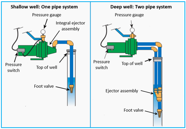
Jet pump
Jet pumps are most commonly used to lift water from wells. There are two different designs that are used based on the depth of the well. The design operates on the principle of a high-pressure fluid jet and the venturi effect, which exerts suction. Essentially, a jet pump is really two pumps in one; a centrifugal pump and a jet assembly commonly called an ejector. The ejector can be attached to the pump body, or it can be located down in the well. The location of the ejector will determine the pumping depth of the jet pump as shown in the figure below.
Peristaltic pump [Level 3]
These pumps are also commonly known as a roller pump. It is a type of positive displacement pump used for pumping a variety of fluids. The fluid is contained in a flexible tube fitted inside a circular pump casing. Most peristaltic pumps work through rotary motion, and are commonly used to pump chemicals, such as in laundry and hospital applications.
Submersible pump
This pump design falls under the centrifugal classification and is a device which has a hermetically sealed motor close-coupled to the pump body. The whole assembly is submerged in the fluid to be pumped. The main advantage of this type of pump is that it does not require priming as the suction is submerged in the fluid. Submersible pumps push fluid to the surface, rather than pull liquid up like a jet pump, which create a vacuum and relies on atmospheric pressure. Plumbers would use submersible pumps as sump pumps, sewage pumps, stormwater pumps, deep well pumps, etc.
The BCPC Figure A-2.4.6.3. Arrangement of Piping at Sump, shows a sump using a submersible pump.
Transfer pumps
These are typically positive displacement gear pumps that are able to pump at high pressures and excel at pumping high viscosity liquids efficiently. An example of a use for this type of pump would be for a plumber to add glycol to a heating system.
Well pumps
The Ground Water Protection Act lists many classes of wells (geotechnical, monitoring, closed-loop geoexchange, etc.) but this section will focus on pumps for water supply wells.
Pumps are needed when a well is used to provide domestic water and the water level in the well is lower than the house or building. There are basically four types of wells (dug, bored, driven, and drilled) which can be divided into two groups, shallow or deep. These terms are referring to the depth of the water source or well. A shallow well is one where the water is within 25 feet of the ground surface. A deep well is where the static water level is more than 25 feet down.
A typical well water system lifts water from an underground well and delivers it to a storage tank where it is pressurized and stored until it is needed. Most well pumps fall into one of two categories, either jet pumps or submersible pumps. Choosing a jet pump or submersible pump will likely depend on the depth of your well. There are many factors involved in selecting the correct well pump and the list below can be used as a general guideline.
- If less than 25′, use a shallow well jet pump
- If 25′ – 110′, use a deep well jet pump
- If 25′ – 400′, use a 4-inch submersible pump
Selecting the correct pump is so important that the Groundwater Protection Regulation (GWPR) lists the rules and requirements for installing well pumps in British Columbia. This means that installing a pump in a well is a restricted activity in B.C., and in most cases may only be performed by a registered well pump installer. Registered well pump installers are certified to work in the province and will install a pump in compliance with the regulations.
In British Columbia, registered well drillers and well pump installers must be members of the BC Ground Water Association (BCGWA). Well pumps are covered in detail in the plumber Level 4 content.
The Municipal Distribution System
Using the flow chart below, the section downstream of Booster pump(s) will be covered next. This section includes many of the pipes, fittings, valves, and appurtenances that a plumber would need to know about if working on the installation or maintenance of a municipal water supply system.
Municipal Distribution System Designs
After water has been treated, pumps move the water to the transmission and distribution network. Modern distribution systems are laid out in a pattern that connect all pipes into one of three piping networks, or a combination of them.
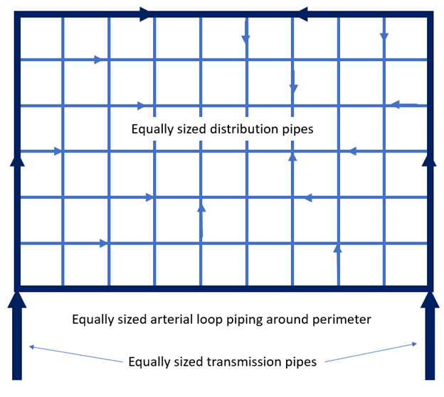
The arterial loop system
This system design is found in areas of the municipality needing large quantities of water or where heavy demand is placed on the system. This system uses two equally sized transmission lines that supply water to equally sized distribution pipes as shown in Figure 13.
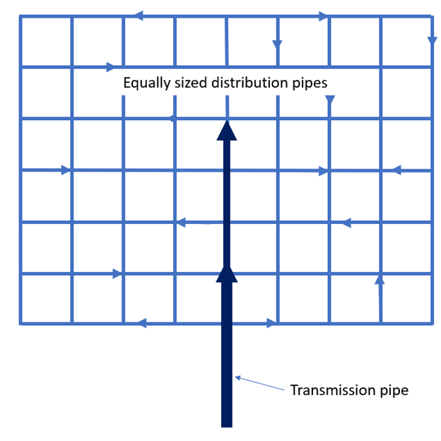
Grid distribution
The second piping arrangement commonly used is the grid distribution system. The grid system is fed by large piping to the middle of the configuration and the main reduces in size as branch pipes are connected to it, similar to Figure 14. The grid system arrangement is similar to the arterial loop configuration, but is fed from one pipe instead of two. The grid system is often installed in conjunction with arterial loop arrangements and is common in cities and built-up areas.
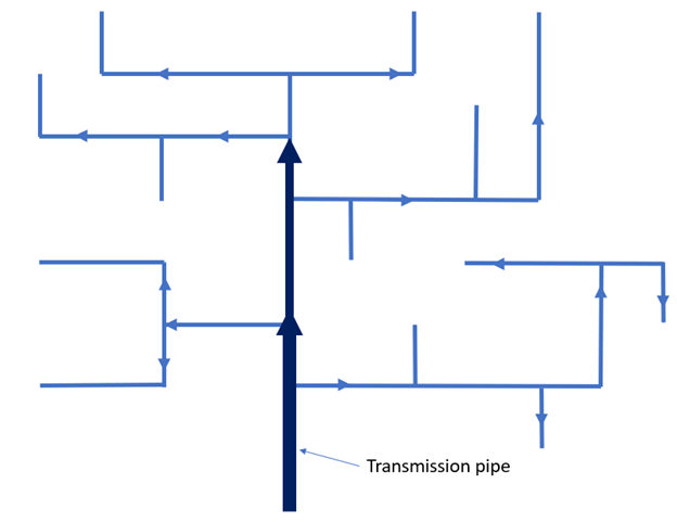
Dead end configuration
A third method is the dead-end configuration (sometimes called the tree system). It is still found in older cities, but not recommended as the primary method of water distribution for new installations. In this system, distribution pipes are fed from a large transmission pipe and smaller branches connect to the distribution piping. Figure 15 shows a simplified dead-end configuration. This arrangement requires fewer isolation valves, but makes it difficult to supply good quality water to all parts of the system. Dead ends of the network must be drained periodically and line breaks or line shutdowns isolate the remaining distribution system. Also, this configuration is prone to taste and odour problems.
Drawings and Specifications
Competencies in the plumber Level 1, Level 2, and Level 3 content have introduced drawings and specifications, so this section will focus on drawings and specifications specific to water supply systems.
Drawings
Recall from previous plumber program content that a drawing (or print) provides dimensions and details of materials of construction, and specifications give details on installation procedures and the standards required for materials. Some installations may have the specifications and all other pertinent information on the drawings in the form of notes. These drawings are known as working drawings.
Architectural, structural, mechanical, and civil drawings might all be used by the plumber to help with the design and installation of the water supply system. On larger projects, the water supply system may be shown on several drawings, with many other mechanical systems combined on the same drawings. This can be a challenge when tracing and interpreting the piping arrangement. It is common for the designer to create either a schematic drawing, or an isometric drawing, of the water piping arrangement as a separate detail or mechanical drawing. In all cases, it is important that the plumber understand how the system is supposed to work in case there are errors on any of the drawings.
One type of schematic drawing sometimes used on larger jobs, such as municipal water supply systems, is called a Piping and Instrumentation Drawing, or P&ID. This type of drawing is a graphic representation of a process system that includes the piping, vessels, control valves, instrumentation, and other process components and equipment in the system. The P&ID is the primary schematic drawing used for laying out a process control system’s installation. As such, the P&ID is crucial in all stages of process system development and operation.
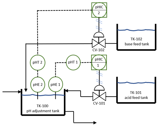
A P&ID will show all major equipment and process streams, but pipe lengths, fittings, or anything not critical to the process represented in the drawing is not shown. Flow direction, line numbers, and pipe sizes are given for the process piping in the drawing, while another set of P&IDs might list piping specifications. An example of a simple P&ID is shown in the figure below.
Figure 16 shows a process maintaining a pH of 7 for a water treatment system. The field-located pH sensor (pHE symbol) reads the pH of the water, which is transmitted through the field-located pH transmitter (pHT symbol) to the indicating control in the remote-located control panel (pHIC symbol). The control operates the pneumatic control valve (CV-101 or 102) as required to maintain the setpoint.
For smaller ICI water distribution system projects, and for most residential water distribution systems, the designer will use either multiple orthographic drawings or an isometric drawing to help determine locations and see potential problems. These types of drawings also work well to transfer information to the tradesperson doing the installation. For example, an isometric sketch can be created during a discussion between a journeyperson plumber and an apprentice to help clarify pipe location, routing, floor and wall penetrations, flow direction, terminations, etc. To aid the installer during the installation of the water piping, notes can be added to any drawing to act as specifications.
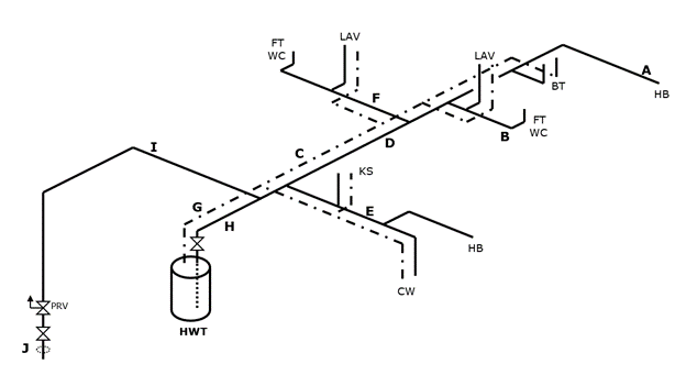
An example of a simple residential waterline sketch is shown in the figure below.
Specifications
Specifications give details on installation procedures and the standards required for materials. The specifications for a hospital could be hundreds of pages, while a separate specifications document for a residential project may not exist. On large, complex, ICI projects the specifications are a living document and are updated as required so the plumber must ensure that the installation is following the latest version. On a basic residential project, the plumber makes decisions on installation standards and material specifications based on meeting the minimum standard of the BC Plumbing Code.
The list that follows is an example of the standards and material specifications that could apply to a municipal water distribution system.
Water Distribution System Standards and Material Specifications
1.0 Standards
- 1.1 Excavation
- 1.2 Disposal of excavated material
- 1.3 Pipe material
- 1.4 Excavated material
- 1.5 Trench preparation
- 1.6 Corrosion protection
- 1.7 Dewatering
- 1.8 Tracer wire
- 1.9 Joint deflection
- 1.10 Backfilling
- 1.11 Connection to existing watermains
- 1.12 Fire hydrants and valves
- 1.13 Water valves and valve boxes
- 1.14 Flushing, testing, and disinfection
2.0 Material Specifications
- 2.1 Watermain pipe
- 2.2 Pipe fittings
- 2.3 Valves
- 2.4 Corrosion protection
- 2.5 Water service pipe
- 2.6 Water meters
3.0 Diagram References
- 3.1 Meter pits
- 3.2 Fire hydrant specifications
- 3.3 Service connections
- 3.4 Trench widths
Elevations
Pipe elevations are shown on several drawings. Plumbers need to know pipe invert elevations for gravity systems such as sanitary and storm sewers but, for the water service pipe, the elevation shown may be the top-of-pipe elevation. Top-of-pipe elevation is shown on the contract drawings where watermains cross a sewer or other obstruction, or to indicate the minimum coverage for freeze protection.
Components and Equipment
Water supply systems incorporate many different types of pipes, fittings, valves, equipment and appurtenances. The BC Plumbing Code prescribes the use of specific materials in some circumstances but the system designer has a lot of flexibility in selecting most of the other components and equipment that makes up the system. The major components and equipment used to construct a water supply system upstream of the water service pipe are described in the following content.
Pressure reducing valves
Water pressure reducing valves (PRVs) are used in residential and ICI applications to reduce incoming water pressure for protection of plumbing system components and to reduce water consumption. Water supply utilities use pumps to increase pressure in water mains to sufficient levels to supply water for firefighting, to overcome loss of pressure in the upper floors of high-rise buildings and to supply water towers and supply tanks. Pressure in water supply mains can exceed 1380 kPa (200 psi).
Since excessive pressure in a water supply system can cause a number of issues, the BC Plumbing Code Article 2.6.3.3 states that “where the static pressure at any fixture may exceed 550 kPa, a pressure-reducing valve shall be installed to limit the maximum static pressure at the fixture to 550 kPa.” Pressure-reducing valves can also greatly reduce the effects of water hammer. They are available within specified pressure ranges and are adjustable within the specified ranges.
There are two types of pressure reducing valves used on water supply systems, direct-acting and pilot-operated.
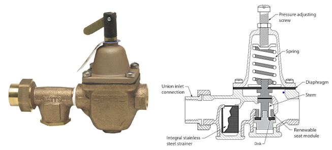
Direct-acting PRV
Direct-acting, spring-loaded PRVs are used for low flow rates. These valves consist of globe-type bodies with a spring-loaded, heat-resistant diaphragm connected to the outlet of the valve that acts upon a spring. This spring holds a pre-set tension on the valve seat installed with a pressure equalizing mechanism for precise water-pressure control. They are the most commonly used PRVs and are found in a range of applications, including residential, OEM, and commercial, where diameters smaller than 3 inches are acceptable.
The parts of a direct-acting PRV are shown in the figure below.
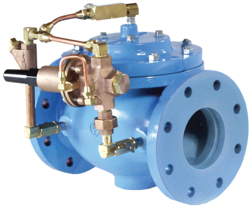
Pilot-operated PRV
Pilot-operated, diaphragm-actuated PRVs are used for higher flow rates. Pilot-operated valves have a sensing control pilot and main valve in one unit. These valves are typically used for commercial applications such as schools, hotels and hospitals, as well as in industrial and municipal applications and installations that require more consistent pressure control over wide flow ranges. Those applications typically demand valves with larger diameters, ranging from 1–¼ inch to 16 inches.
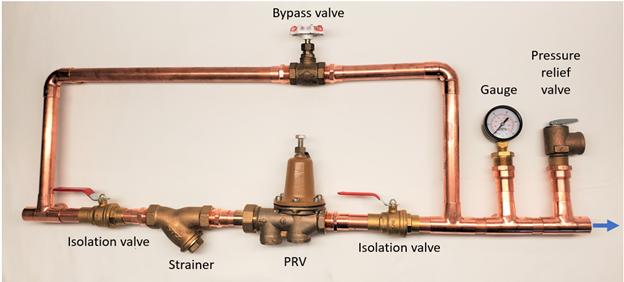
Pressure-reducing valve installation considerations
When installing pressure-reducing valves, it is very important to follow the manufacturer’s installation instructions. Proper installation techniques will result in trouble-free operation and ease of maintenance. The content below lists several additional components that the plumber could install with the PRV.
- Installing shut-off valves (ball or gate) and bypasses (globe) will permit removal or repair of a PRV without disruption of water supply to the building or to the fixture or appliance that the PRV is serving.
- A strainer is often installed on the high-pressure side to prevent dirt and debris from becoming lodged between the valve seat and disc, preventing it from shutting off. If a PRV fails to shut off, the pressure may rise to a dangerous level. The strainer can be a separate component or it can be integral to the PRV body.
- A pressure-relief valve is typically installed on the downstream side of the PRV when it is used to supply domestic water in a high-pressure application. Failure of the PRV or improper throttling of the bypass valve during repairs to the PRV could cause a dangerous high-pressure condition downstream. If this occurred, the pressure-relief valve would activate and relieve the excess pressure.
- A pressure gauge could be used in conjunction with a PRV to set and monitor the outlet pressure. An optional pressure gauge is often installed upstream of the PRV to indicate the inlet pressure.
Series installation of pressure-reducing valves
When a second PRV is installed immediately downstream of the first PRV it is referred to as series, or two-stage, regulation. This design is used for greater pressure reduction than that provided by a single valve. Series use of pressure-reducing valves may be necessary where pressure reduction is required to a fixture such as a commercial dishwasher or drinking fountain.
Pressure-reducing valves are also used in series in a downfeed riser in a tall building. Downfeed building distribution systems are discussed in detail in Competency B-2.
Parallel installation of pressure-reducing valves
Two (or more) pressure-reducing valves are often installed side by side to replace one large, expensive valve. This installation also eliminates the need for a valve bypass, as one valve can be removed from the line for repair or maintenance while the other continues to meet the demands of the supply system at a reduced rate.
When two or more small pressure-reducing valves are used to replace a large valve in a parallel installation, one might be set at a slightly higher opening pressure so as to prevent both valves from operating during low-demand periods. This cuts down on valve seat etching caused by the passage of water between the valve seat and disc. It also reduces maintenance costs by causing only one valve to be in constant operation.
Where two PRVs are used, a smaller valve might be installed parallel to the large valve. The smaller valve can handle very low-demand periods, such as a single fixture being used, while the larger PRV handles the peak demand flow. This setup is also less noisy, as the PRV valve is more closely sized for the flow during minimal flow conditions.
Air release and vacuum relief valves
The design of a water supply system must allow for removal of air when filling the system and for vacuum relief when draining the system. Air trapped in a piping will naturally rise and collect at high points within the system. This trapped air can cause pump failures, faulty instrumentation readings, corrosion, flow issues, and water hammer or pressure surges. Unnecessary air in the pipeline also makes the pump work harder, resulting in additional energy consumption. Air in the piping comes from three primary sources:
- The piping itself – Before start-up, a piping system isn’t technically empty, it’s filled with air. As water fills the piping, the air must be allowed to evacuate.
- Pumping – Water contains 2% air by volume. As the water is pumped through the system, air separates and accumulates at system high points.
- Mechanical equipment – Air can be drawn into the system through equipment like pumps, packing, valves, and pipe joints.
A vacuum relief valve is used to prevent a vacuum condition from occurring in the piping. The valve will admit large volumes of air to prevent a vacuum when draining the system for planned maintenance, or in the event of an emergency such as an accidental line break.
There are several options for air and vacuum relief valves, depending on the system designer’s preference:
- Manually-operated valves
- Air release valve only
- Vacuum relief valve only
- Separate air release and vacuum relief valves
- Combination air release and vacuum relief valves
The figures below show a combination air release and vacuum relief valve in operation.
During the filling of the line, air enters the valve body and is released to the atmosphere. When the air is expelled and the water enters the valve, the float will rise and cause the orifices to be closed. The large and small orifices of the air and vacuum valve are normally held closed by the buoyant force of the float.
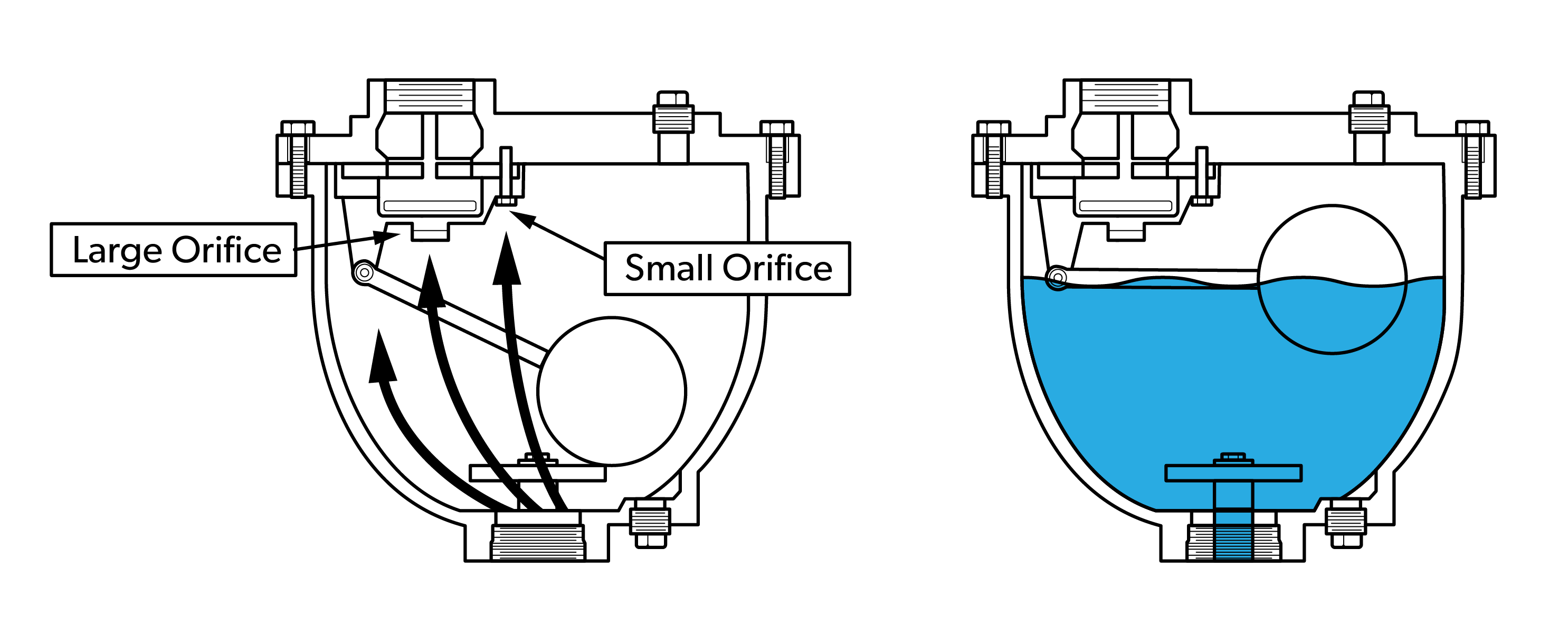
While the line is working under pressure, small amounts of trapped or entrained air are exhausted to the atmosphere through the small orifice in the combination air release and vacuum relief valve, as shown in the figure below.
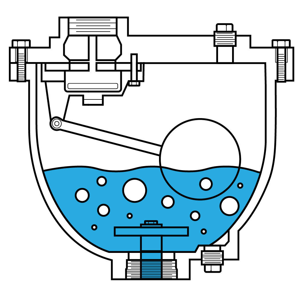
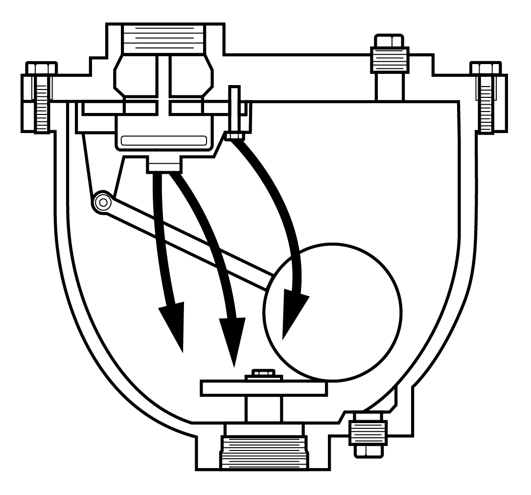
Air is permitted to enter the combination air release and vacuum relief valve and replace the water while the line is being drained.
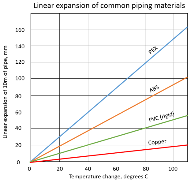
Expansion control
The need for thermal expansion control in piping systems arises from the tendency of the pipe to expand or contract due to changes in temperature of the pipe material. Sentence 2.3.3.9.(1) in the BC Plumbing Code addresses the need for expansion control by stating “The design and installation of every piping system shall include means to accommodate its expansion and contraction caused by temperature changes, movement of the soil, building shrinkage or structural settlement.” The BC Plumbing Code Notes to Part 2, A-2.3.3.9, has a figure similar to the one shown below that compares different materials and their linear expansion rate.
Expansion control for underground water piping
Underground water piping is dealt with differently than above ground water piping since the temperature differential is significantly less for buried piping. The temperature of the ground remains fairly constant and, since the water is relatively close to the ground temperature, there is usually no need for expansion control for underground water supply piping. Rubber reinforced expansion joints are available if the water supply system designer decides expansion control is required for underground piping. Some types of underground pipe connections will also allow for expansion and contraction because of the nature of the push-on or mechanical joint. Pipe and fittings and the connection methods are covered in Learning Task 3 of this Competency.
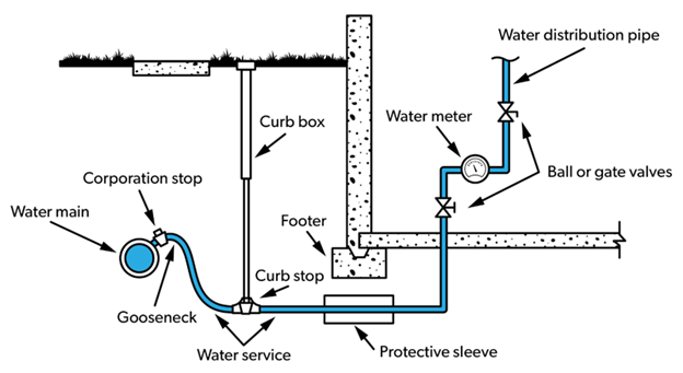
There is one location in the underground water supply system where an expansion loop (also referred to as a settlement loop or gooseneck) is used. Figure 25 shows how an S-shaped bend is placed in the water service connection of small diameter, flexible pipe at the upstream end to provide a minor amount of movement for the water service connection. This helps to prevent breakage of the corporation main stop or the service connection as backfill settles, from expansion, or ground movement from frost or traffic. Service lines over 2 inches (50 mm) do not require a settlement loop.
Expansion control for above-ground water piping
Above-ground water supply piping may need to be installed with methods to control or accommodate expansion and contraction since the temperature differential can be significant when considering the difference between the ambient air temperature and the potential temperature of hot water in the piping. Since the BC Plumbing Code doesn’t give direction on how to accommodate expansion and contraction of above-ground water distribution piping, designers and installers must come up with solutions based on each situation.
Expansion and contraction in piping systems may be accommodated in a number of ways including (but not limited to) piping design and layout, material selection, and the inclusion of expansion joints, offsets, and expansion loops in the piping arrangement. Specially designed hangers and supports may be needed to allow the pipe to expand and contract without causing unnecessary force on fittings and joints. The installer must be careful not to unintentionally restrict pipe movement by creating restraint or anchor points in a piping arrangement.
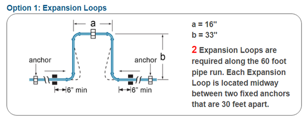
Most pipe and fitting manufacturers have documentation on how to allow for expansion and contraction of their products. Some manufacturers, like IPEX, have expansion calculators for their Aquarise® potable water products. For example, if a 60-foot run of 2 inch Aquarise® was installed inside a building and used for the hot water distribution system, option 1 shown below is calculated using the IPEX online calculator.
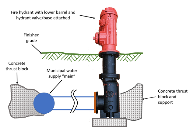
Fire hydrants
Municipal water supply systems are designed for maximum peak-demand flow and for fire-fighting demands that could be placed on the system. In most cases, fire hydrants are connected to the municipal water supply system. If fire hydrants are required on private property, a separate water supply is usually supplied. This separate supply is to ensure an adequate supply of water under fire-fighting conditions, which may not be possible if the connection was on the water service pipe, or downstream of a water meter. If the municipal water supply system cannot provide the minimum volume of water required for fire-fighting on private property, a separate private water supply may have to be provided for the fire hydrant system.
There are many fire protection systems installed inside of buildings that are connected to the potable water supply. These systems are designed and installed by trained persons in the Sprinkler Fitter trade.
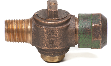
Corporation stop
The corporation stop, or corporation valve, is the valve installed on a municipal water main to permit joining of the water service pipe. The valve may be threaded into a tapped coupling (tee fitting), threaded into a service saddle, or direct-tapped into the water main. The valve may have flared, iron pipe thread, flanged or compression outlet connections. The inlet thread of 2 inch (50mm) or smaller corporation main stops has traditionally been made to specifications developed by the AWWA and is commonly called a Mueller thread. These threads are NOT pipe threads. However, many purveyors now use National pipe thread connections up to 2 inches in size. Most corporation stops over 2 inches are threaded or flanged.
Small corporation main stops can not be opened or closed from ground surface, as they are covered over with backfill. If they must be closed for any reason, they must be excavated to expose them. Larger services typically use gate or globe valves as service shutoff valves connected to the distribution main with a tapping tee or split tee.
The corporation stop connection to the water main can be done while the system is de-pressurized, or it can be done by hot-tapping (also called live-tapping) while the pipe is under pressure. Hot-tapping is covered in Learning Task 3 of this Competency.
Ideally, a corporation stop is installed above the horizontal centreline of the water main to prevent sediment from entering the service pipe.
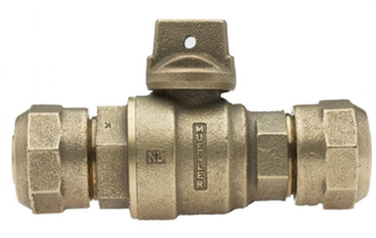
Curb Stop
Moving downstream from the Water services section on the municipal water supply system flow chart, we come to the curb stop. For the purposes of this content, the curb stop is where the municipal water supply system ends and where the plumber will begin interacting with the water supply system. It is common for the plumber to connect to an existing curb stop and to continue with the design and/or installation of the water service pipe and the building water distribution system.
On municipal water supply systems, the curb stop is located at the curb line, or just outside the customer’s property line. This valve is used to allow the service to be shut off for repair or non-payment of utility fees. The curb stop is installed below ground, the depth depending on local frost depth conditions. In areas where the frost depth is minimal, the curb stop is located in the water meter box and is readily accessible in case of an emergency. Where the frost depth is deeper, the curb stop is buried well below the finished grade and the valve stem is either extended to the surface with a curb box, or is only accessible with a curb stop key (valve stem extension rod).
If the curb stop is installed with a water meter, in a meter box, it is common for the purveyor to use an angle curb stop to allow for easier assembly and disassembly. There are several combinations for piping and tubing sizes and types for the purveyor and plumber to choose from, requiring curb stops to have inlet and outlet connections that match most combinations.
The purveyor may install a curb stop chair (shoe) under the curb stop to support the stop and the extension. This support frame prevents deflection of the service pipe as the buried curb stop valve is operated. Since the curb stop is owned by the water purveyor, the plumber must communicate with the purveyor before operating the valve.
The figure below shows a curb stop well below grade with a curb box installed to allow for operating the valve.
There is a wide variety of curb stop designs and styles depending on the upstream and downstream connections. Common materials of construction for small diameter (residential size) valves are bronze and red brass, with older versions being plug valves, and newer versions being ball valves.
Now complete Self-Test 1 and check your answers.
Self-Test 1
Self-Test 1
- How is potable water defined?
- Water in its natural state, like rainwater, groundwater
- Water that has the minimum allowable level of contaminants
- Water that will not injure the health of humans drinking the water
- Water that meets the prescribed standard(s), and is safe to drink and fit for domestic purposes without further treatment
- How is a water service pipe defined?
- A pipe that conveys water from the water meter to inside the building
- A pipe that carries water from the water meter to the most remote fixture
- A pipe that carries water from the curb stop to the most remote fixture in the building
- A pipe that conveys water from a public water main or private water source to the inside of the building
- Transpiration is water that evaporates from plants into the atmosphere.
- True
- False
- Water is a natural solvent.
- True
- False
- What is the name used to describe the water from a public water system after it has passed through the consumer’s service connection?
- Used water
- Potable water
- Domestic water
- Customer water
- As water flows through a centrifugal pump, it slows down and the pressure:
- Pulsates
- Increases
- Decreases
- Remains the same
- The friction loss of fittings and valves is usually expressed in:
- Head loss in feet
- Pressure loss per inch
- Head loss per square inch
- Equivalent lengths of straight pipe
- What information is required when using a performance curve to select a pump?
- Pump head and static pressure
- Pump head and pump capacity
- Vertical lift and total pressure loss
- Pump horsepower and pump capacity
- Which municipal water distribution system is prone to taste and odour problems?
- Arterial loop system
- Grid distribution
- Dead end configuration
- Trunk and branch system
- According to the BC Plumbing Code what is the maximum static pressure allowed at a fixture before a pressure-reducing valve is installed?
- 350 kPa
- 500 kPa
- 550 kPa
- 700 kPa
- What is the most commonly used PRV for residential, and small diameter commercial, water systems?
- Direct-acting
- Indirect-acting
- Pilot direct-acting
- Pilot indirect-acting
- What is the purpose of series installation of pressure-reducing valves?
- Less chance of backflow
- Two-stage pressure reduction
- More flow through smaller PRVs
- Cost savings compared to one large PRV
- Where is a corporation valve installed?
- Upstream of a fire hydrant to allow for servicing
- On every water service pipe where it enters the building
- On a corporation trunk line to allow for water main isolation
- On a municipal water main to permit joining of the water service pipe
- What is the purpose of a curb stop?
- Allow for water meter servicing (not every municipality uses meters)
- Prevent backflow of used water into the municipal water main
- Allow the service to be shut off for repair or non-payment of utility fees
- Allow for the connection of the water service pipe to the municipal water main
- When may a private water supply system be interconnected with a public water supply system?
- If is only used for irrigation
- No interconnection is permitted
- If a reduced pressure assembly is installed
- If a double check valve assembly is installed
Check your answers using the Self-Test Answer Keys in Appendix 1.
Image Descriptions
Figure 1 Water system from source to tap
- Watershed
- Dam or intake
- Raw water main
- Water treatment facility
- Pump station
- Water reservoir
- Water main
- Pump station
- Water main
- Water distribution main
- Water main connects to plumbing inside your home.
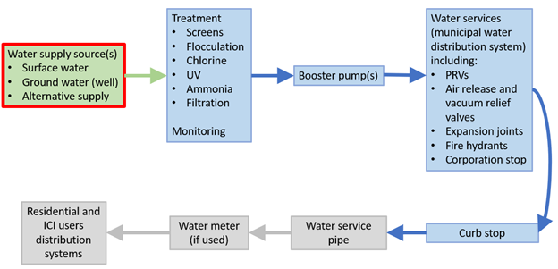
Figure 2 Source to tap flow chart
Example of a flow chart for a municipal water supply system
- Public water source(s)
- Surface water
- Ground water (well)
- Alternate supply
- Treatment
- Screens
- Flocculation
- Chlorine
- UV
- Ammonia
- Filtration
Monitoring
- Booster pump(s)
- Water services (municipal water distribution system) including:
- PRVs
- Air release and vacuum relief valves
- Fire Hydrants
- Corporation stop
- Curb stop
- Water service pipe
- Water meter (if used)
- Residential and ICI user distribution systems
Figure 7 Simplified list of pump categories and types
Different types of pumps
- Centrifugal pumps
- Axial flow
- Radial flow
- Horizontal type
- Vertical type
- Submersible type
- Positive displacement pumps
- Reciprocating type
- Rotary type
Image Attributions
- Figure 1 Water system from source to tap by Camosun College is licensed under a CC BY 4.0 licence.
- Figure 2 Source to tap flow chart by John Gordon is licensed under a CC BY-NC-SA licence.
- Figure 3 The water cycle by John Gordon is licensed under a CC BY-NC-SA licence.
- Figure 4, 5, 6, 12 & 29 Source to tap flow chart with different parts emphasized by John Gordon is licensed under a CC BY-NC-SA licence.
- Figure 7 Simplified list of pump categories and types by John Gordon is licensed under a CC BY-NC-SA licence.
- Figure 8 – Simplified centrifugal pump cutaway showing parts and their names by ITA is licensed under a CC BY-NC-SA licence.
- Figure 9 One design of a reciprocating pump
- Figure 10 Examples of rotary pumps by John Gordon is licensed under a CC BY-NC-SA licence.
- Figure 11 Jet pump designs by John Gordon is licensed under a CC BY-NC-SA licence.
- Figure 13 Arterial loop municipal distribution system by John Gordon is licensed under a CC BY-NC-SA licence.
- Figure 14 Grid municipal distribution system by John Gordon is licensed under a CC BY-NC-SA licence.
- Figure 15 Dead-end municipal distribution system by John Gordon is licensed under a CC BY-NC-SA licence.
- Figure 16 Simple P&ID of a pH adjustment system for water treatment by John Gordon is licensed under a CC BY-NC-SA licence.
- Figure 17 Example of a sketch of a residential building water supply system by Scott Armor, Camosun College Piping Department is licensed under a CC BY 4.0 licence.
- Figure 18 Comparison of an actual direct-acting PRV with strainer and a cutaway showing the parts by Camosun College is licensed under a CC BY 4.0 licence.
- Figure 19 Pilot-operated water pressure regulator by Camosun College is licensed under a CC BY 4.0 licence.
- Figure 20 Pressure-reducing valve station showing additional components by Camosun College is licensed under a CC BY 4.0 licence.
- Figure 21 Combination valve operation showing air being expelled on the left, and the valve closed by water on the right by Camosun College is licensed under a CC BY 4.0 licence.
- Figure 22 Combination valve operation showing entrained air being exhausted by Camosun College is licensed under a CC BY 4.0 licence.
- Figure 23 Combination valve operation showing air entry when piping is drained by Camosun College is licensed under a CC BY 4.0 licence.
- Figure 24 Different piping materials and their linear expansion rate by John Gordon is licensed under a CC BY-NC-SA licence.
- Figure 25 Residential water supply system showing a gooseneck, or expansion loop, on the service pipe by Camosun College is licensed under a CC BY 4.0 licence.
- Figure 26 One example of an expansion loop design for above-ground water piping by Camosun College is licensed under a CC BY 4.0 licence.
- Figure 27 Fire hydrant connection to a municipal water supply system John Gordon is licensed under a CC BY-NC-SA licence.
- Figure 28 A small diameter, quarter-turn, residential-style corporation stop by Camosun College is licensed under a CC BY 4.0 licence.
- Figure 30 Residential water supply system showing a curb box by Camosun College is licensed under a CC BY 4.0 licence.
- Figure 31 Quarter-turn ball valve design curb stop with compression type connections by Camosun College is licensed under a CC BY 4.0 licence.
