Learning Task 1
Describe the Building Water Supply System
The plumber is responsible for the installation of the piping that delivers water to a building, distributes water to various plumbing fixtures, and installing specialized systems related to the building water supply.
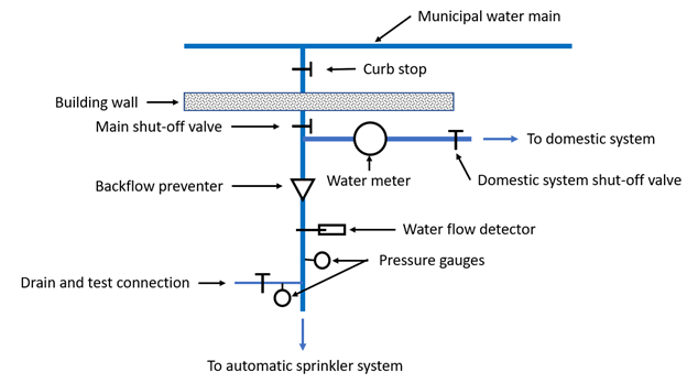
The term building water supply system was used in Competency B1 to differentiate the water distribution system downstream of the curb stop from the system upstream of the curb stop. The term comprises the water service pipe and the building distribution system. Plumbers are involved in the design and installation of this part of the system.
The building water distribution piping may supply a simple residential system, or it may supply a complex industrial, commercial, or institutional (ICI) system. The content in this Competency will cover the installation of the pipes, fittings, valves and appurtenances that make up both residential and ICI distribution systems, as well as describe several specialized systems and specialized components that are commonly included as part of a building water distribution system.
Terminology
Many of the terms that apply to a water supply system were defined in Competency B1.
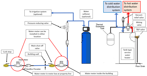
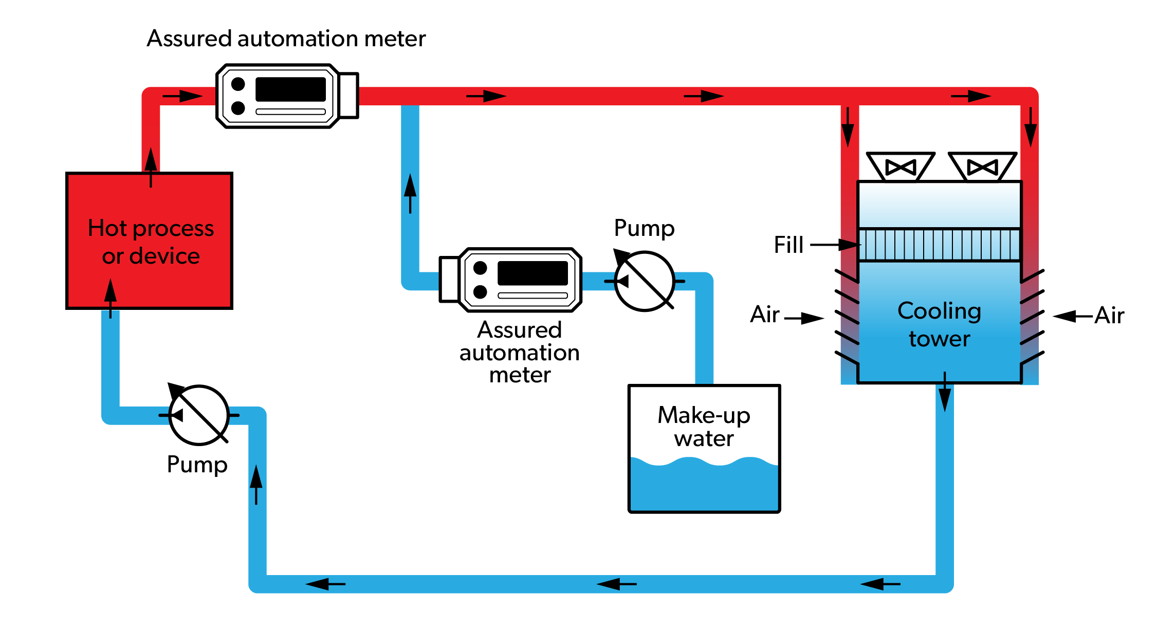
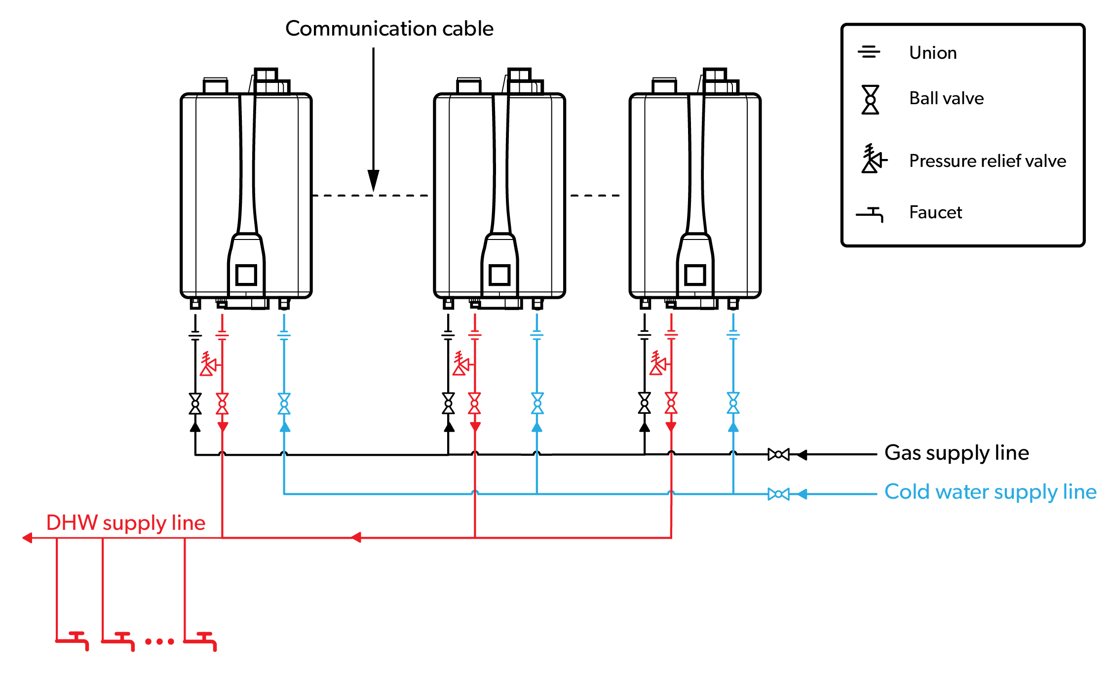
Figure 1 can be used to identify components that are used specifically in the building water supply system and are defined in this terminology section.
Backflow Preventer
The BC Plumbing Code defines a backflow preventer as a device or a method that prevents backflow. Check valves are commonly used in backflow preventer assemblies and are considered nonreturn valves.
Building Water Distribution System
The BC Plumbing Code defines the term “water distribution system” as an assembly of pipes, fittings, valves and appurtenances that conveys water from the water service pipe or private water supply system to water supply outlets, fixtures, appliances and devices. Although the BC Plumbing Code implies that a water distribution system is the piping and components downstream of the curb stop, the term “distribution system” also gets used to describe parts of the municipal water supply system that is upstream of the curb stop. For the purposes of this competency, the term “building water distribution system” will be used to define the water distribution system inside the building. It includes the service hot water heater and hot and cold water piping.
Domestic Purposes
This term means the use of water for human consumption, food preparation or sanitation.
Hose Bibb
A hose bibb is a valve installed on the end of a water distribution pipe that terminates outside of the building envelope. Hose bibbs typically have a mounting flange and external threads to attach a garden hose. A sediment faucet also has external garden hose threads, but does not have a mounting flange for attachment to the building exterior finish. Sediment faucets are typically used for interior applications, such as water heater drains and boiler drains, but can be used as hose bibbs.
Governing Fixture
The fixture or device connected to a building water distribution system that requires more pressure than the others to operate correctly.
Service Water Heater
The BC Plumbing Code defines this term as a device for heating water for plumbing services.
Water Service Pipe
The BC Plumbing Code defines this term as a pipe that conveys water from a public water main or private water source to the inside of the building.
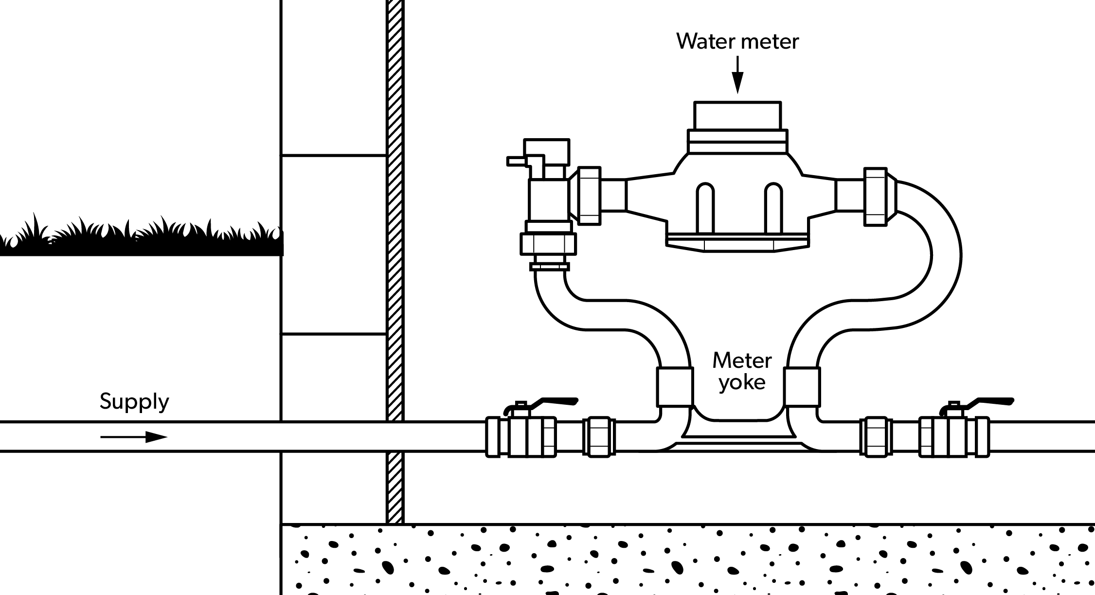
Water Meter
A water meter is a device used to measure the volume of water that passes through a water service.
The Water Service Pipe
The building water service pipe is the most upstream part of the building water supply system. The BC Plumbing Code (BCPC) defines the water service as a pipe that conveys water from a public water main or private water source to the inside of the building. The water service pipe that is part of a private water source will be covered in the plumber Level 4 content. The water service pipe connection to a public water main was covered in the Competency B1 content, as well as the type of piping and fittings used for large (4 inch and larger) ICI water service systems. The content in this section will cover the piping and components that are used for small diameter (sizes less than 4 inches) water service piping and fittings for residential and ICI buildings. Learning Task 3 of this Competency, “Describe the installation of the building water supply system,” will cover the piping and fitting materials for small diameter building water service systems.
Water Meters
In most urban areas, water is supplied and distributed by a municipal water supply system, which will include a water meter on the water service pipe. A water meter is a device that is installed to accurately measure and record the volume of water passing through the pipe. The end user (consumer) usually must pay for the water they use. To determine the cost of the water that is used, a water meter can be installed in the building water service line so a consumer is billed on the exact flow recorded through the meter. However, some purveyors do not use a water meter; instead, the consumer pays a flat rate. In a flat rate system, the consumer pays a pre-set monthly or yearly charge regardless of the amount of water used. Studies have shown that purveyors that use a metered service use approximately 40 percent less water per person compared to services that are not metered.
Water meter locations
Figure 1 shows optional locations for the water meter installation for a simple building water supply system. One optional location is on the building water service pipe immediately downstream of the curb stop. This location would be acceptable only if the Authority Having Jurisdiction (AHJ) determined the depth of the installation would protect against freezing. In British Columbia, many jurisdictions on the south coast allow water meters on residential systems to be installed outside, at the property line. For this type of installation, the water meter would be installed in a meter box, making it accessible from finished grade.
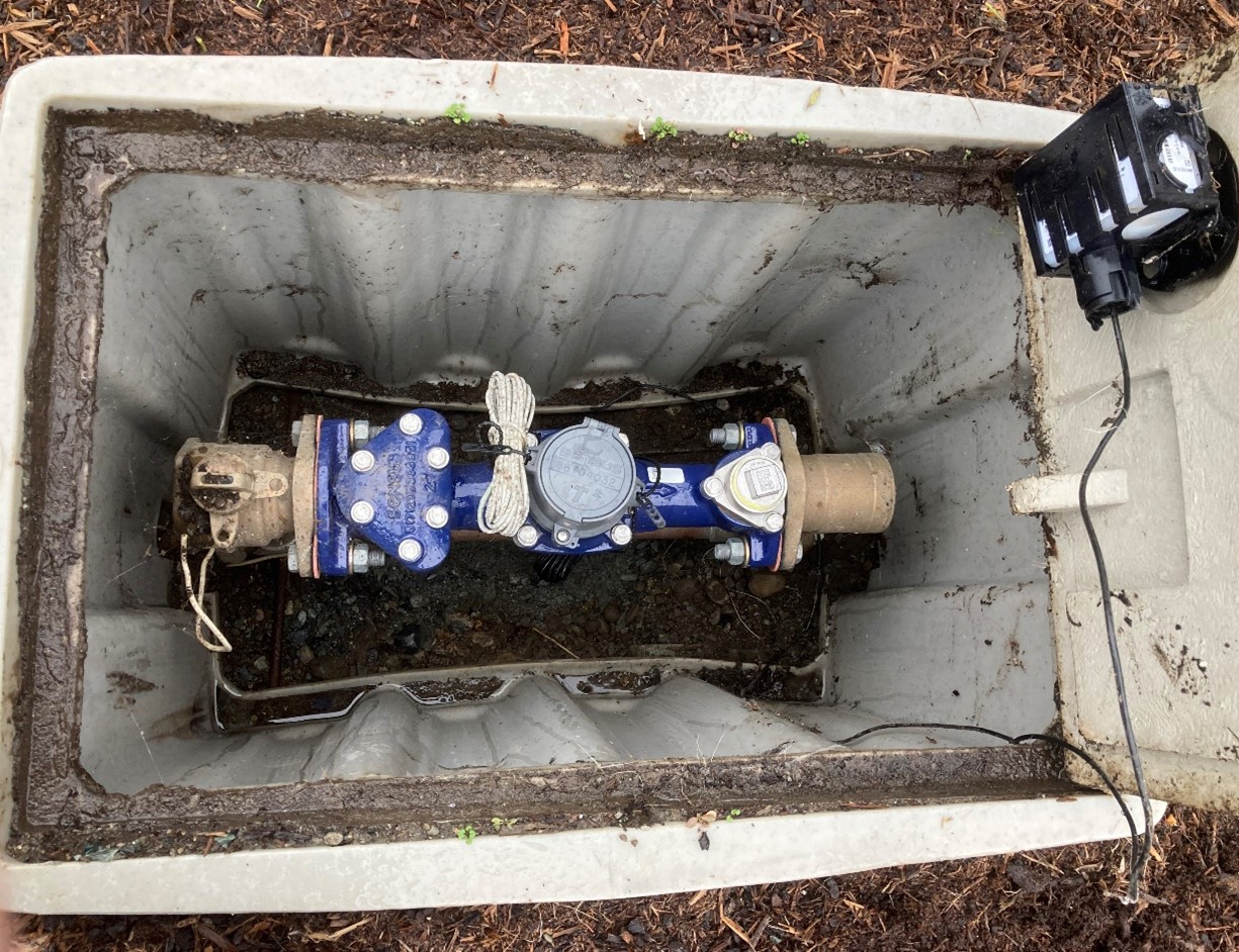
Figure 2 shows a 2-inch water meter, with bypass and V-shaped integral strainer, installed in a meter box at the property line. This installation also incorporates a remote reader option.
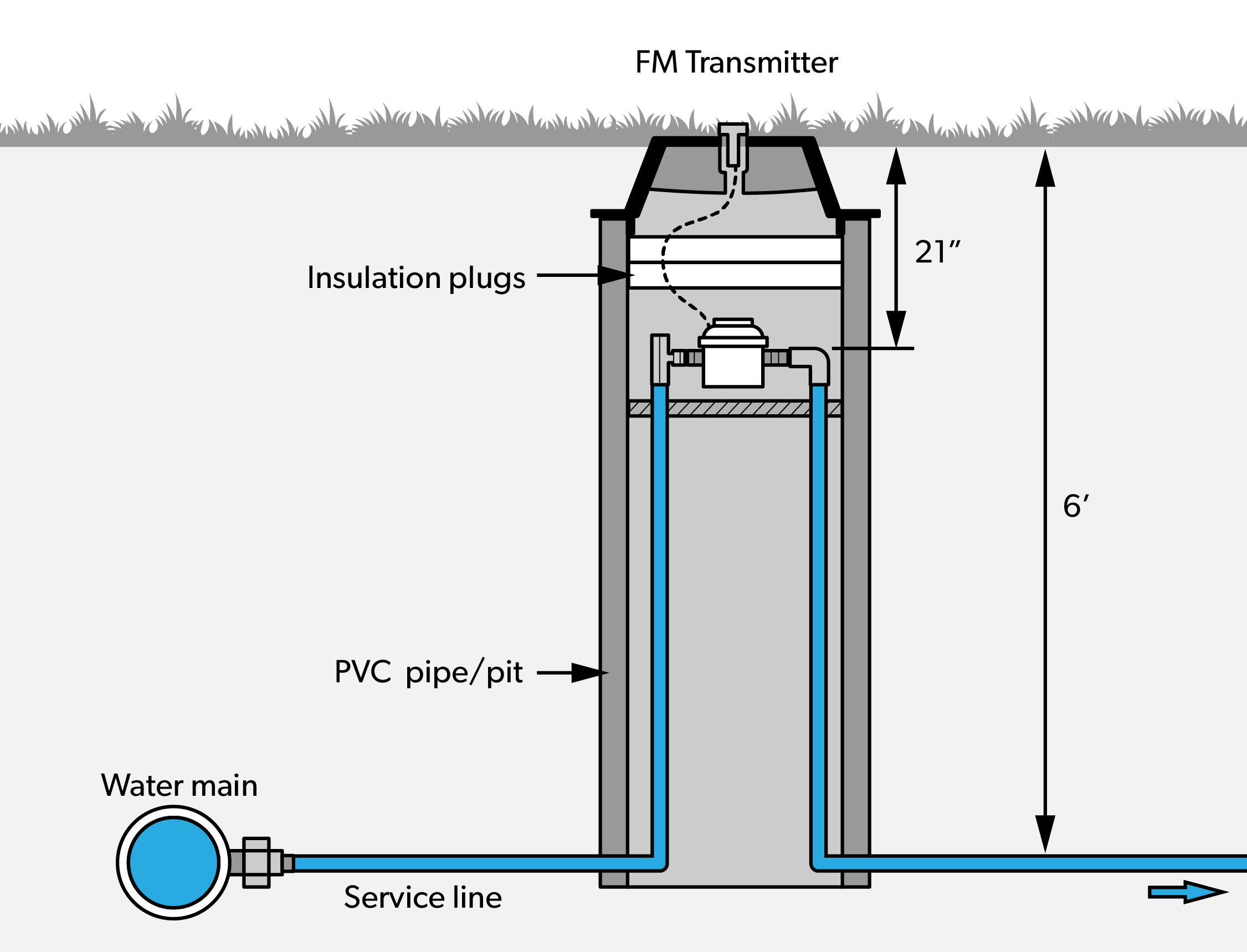
Installations where the frost depth determines the water service pipe must be buried at a depth that makes it impracticable to use a meter box will usually require that the water meter gets installed inside a heated building. Some jurisdictions will allow a water meter to be installed in a meter pit, which keeps the water service pipe below the frost depth, but brings the water meter up to an accessible depth. These types of installations will require some form of insulation, or alternate freeze protection, to protect the water meter and the associated piping and appurtenances.
If the curb stop is installed with a water meter in a meter box or meter pit, it is common for the purveyor to use an angle curb stop to allow for easier assembly and disassembly. There are several combinations for piping and tubing sizes and types for the purveyor and plumber to choose from, requiring curb stops to have inlet and outlet connections that match most combinations. Other components may also be required by the purveyor. The use of a backflow preventer is common on municipal water service connections. The backflow preventer can be located in the meter box or meter pit for outside installations, or it can be located adjacent to the water meter for inside installations. Backflow preventers are covered in detail as part of the Cross Connection content in the Block C section of the Level 3 content
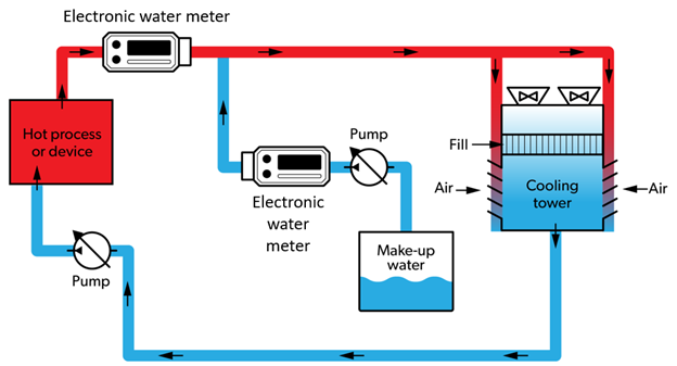
The figure below shows an example of an inside installation with a backflow preventer installed downstream of the water meter.
Water meters are installed in many locations other than on a water service line. In certain ICI applications, the amount of water passing through specific equipment is often recorded. For example, meters may be installed in the water softener supply to large-capacity industrial water softeners in order to determine when regeneration is necessary. Meters may be used to relay signals to control the operation of equipment. In certain ICI processes, chemicals must be added to the water. Generally, this involves adding a predetermined amount of chemical to a predetermined volume of water. A meter can be used to activate a chemical pump or injector each time the predetermined volume of water passes through the meter.
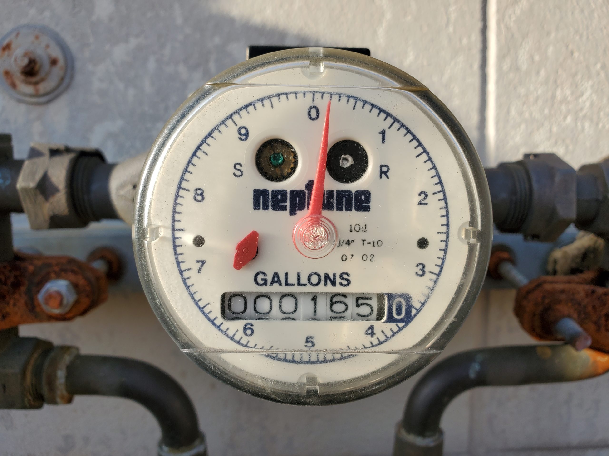
One benefit to having a water meter installed is that it can be used to determine if a leak is occurring, or if there is unauthorized use of water taking place. The small dial on the meter can be used to see if flow is occurring.
The figure below shows the water meter face with a small red dial that rotates whenever flow is occurring.
Water meter types
Meters are available in a variety of sizes and designs. The type of meter chosen for a particular installation generally depends on the size of the service or supply pipe and on the expected flow rate through the meter.
Meters are classified into two basic types: positive displacement and velocity. Each of these meter types has variations, leading to the perception that there are several different kinds. Meters that feature both positive displacement and velocity are known as compound meters. The unit of measurement can be in gallons, or it can be in cubic feet or cubic meters.
Positive displacement meters
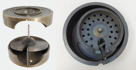
In this type of meter, a known volume of liquid in a tiny compartment moves with the flow of water. Positive displacement flow meters operate by repeatedly filling and emptying these compartments. The flow rate is calculated based on the number of times these compartments are filled and emptied. The movement of a disc or piston drives an arrangement of gears that registers and records the volume of liquid exiting the meter. There are two types of positive displacement meters: nutating disc and piston.
Nutating disc meters, also called rotating disc meters, have a round disc that is located inside a cylindrical chamber. The disc is mounted on a spindle. The disk nutates, or wobbles, as it passes a known volume of liquid through the cylindrical chamber. The rotating motion of the disk is then transmitted to the register that records the volume of water that went through the meter.
Piston meters have a piston that oscillates back and forth as water flows through the meter. A known volume of water is measured for each rotation, and the motion is transmitted to a register through an arrangement of magnetic drive and gear assembly.
Small diameter water meters with the base or bottom of the meter constructed of cast iron or plastic are installed where freezing might occur. The design contains a weak point that will fracture when freezing water expands, thereby keeping the more expensive parts of the meter from being damaged. This meter is typically available in [latex]\dfrac{5}{8}[/latex]″, [latex]\dfrac{3}{4}[/latex]″ and 1″ sizes and is used extensively for residential applications.
The figures below show a nutating-disc design on the left and a piston design on the right.
Positive displacement meters are sensitive to low flow rates and have high accuracy over a wide range of flow rates. These meters are used in homes, small businesses, hotels, and apartment complexes. They are typically available in sizes from [latex]\dfrac{5}{8}[/latex] inch to 2 inches.
Velocity meters
Velocity meters operate on the principle that water passing through a known cross-sectional area with a measured velocity can be equated into a volume of flow. Velocity meters are good for high flow applications. Velocity meters come in different types, including magnetic, multi-jet, orifice, propeller, turbine, ultrasonic, venturi. These meters are available in sizes of two inches and larger with the exception of multi-jet meters, which are between [latex]\dfrac{5}{8}[/latex] inch and 2 inches.
Magnetic meters have an insulated section through which water flows. The flow of water induces an electrical current that is proportional to the velocity and hence the flow rate.
Multi-jet meters have tangential openings in a chamber to direct the water flow across a rotor with many vanes. Flow is measured proportional to the speed of the rotor.
Orifice meters work on the same principle as venturi meters, except that, instead of the decreasing cross-sectional area, there is a circular disk with a concentric hole. Flow rate is calculated similarly to the venturi meter by measuring the difference in pressures.
Propeller meters have a fan-shaped rotor that spins with the flow of water. A recorder is attached to the rotor to register the readings.
Turbine meters have a rotating element that turns with the flow of water. Volume of water is measured by the number of revolutions by the rotor.
Ultrasonic meters send sound waves diagonally across the flow of water in the pipe. Changes in the velocity of water are converted electronically to change in flow rate.
Venturi meters have a section that has a smaller diameter than the pipe on the upstream side. Based on a principle of hydraulics, as water flows through the pipe, its velocity is increased as it flows through a reduced cross-sectional area. Difference in pressure before water enters the smaller diameter section and at the smaller diameter “throat” is measured. The change in pressure is proportional to the square of velocity. Flow rate can be determined by measuring the difference in pressure. Venturi meters are suitable for large pipelines and do not require much maintenance.
Compound meters
In some cases, it is necessary to have a combination meter—both a positive displacement meter and velocity meter installed together—to be able to measure high and low flows. Low flows are measured through positive displacement while high flows are measured by velocity. A valve arrangement directs flows into each part of the meter.
Water meter installation
As discussed previously, it is common to have a meter installed inside a heated building or, alternatively, the meter can be installed in a meter box outside. Although not always possible because of the requirement of freeze protection, it is better to have the meter located at the curb or property line because of easy access for reading or maintenance. It is sometimes difficult to gain access to the residence or building when no one is there. If not installed inside a heated building, large meters are usually installed in underground concrete or block vaults, preferably out of traffic areas. If the meter is installed in a vault (large meter pit), the vault should have a drain, or a sump pump if a drain is not possible. There should never be standing water in the vault.
The water service pipe may not have any outlets placed upstream of the meter location, other than meter bypass arrangements or fire protection system connections. This is to ensure all water used for consumption is accounted for. Also, there is less possibility of unauthorized use of water, a situation termed “theft of services.” To prevent disruption of service when replacing or repairing large meters, there should be a bypass that can also be metered. The minimum size of water service that is permitted to have a bypass arrangement around the meter is typically 1½ inch (approximately 40mm). The bypass must include a shut off valve that will be sealed by the water purveyor by applying strong wire around the pipe and through the valve handle.
Having the bypass metered would be similar to a manifold set-up where you have two or more meters in parallel, making service of one meter easy without service disruption or lost revenue. Large meter installations should have good structural support to prevent stress on the water line. Also, there should be at least ten times the pipe diameter of straight pipe before the meter and five times the pipe diameter of straight pipe after the meter. Some large meters recommend or require a strainer to be installed ahead of the meter.
Remember: if anyone has to enter the meter vault or large pit, this is considered a confined space entry and the proper safety procedures must be followed.
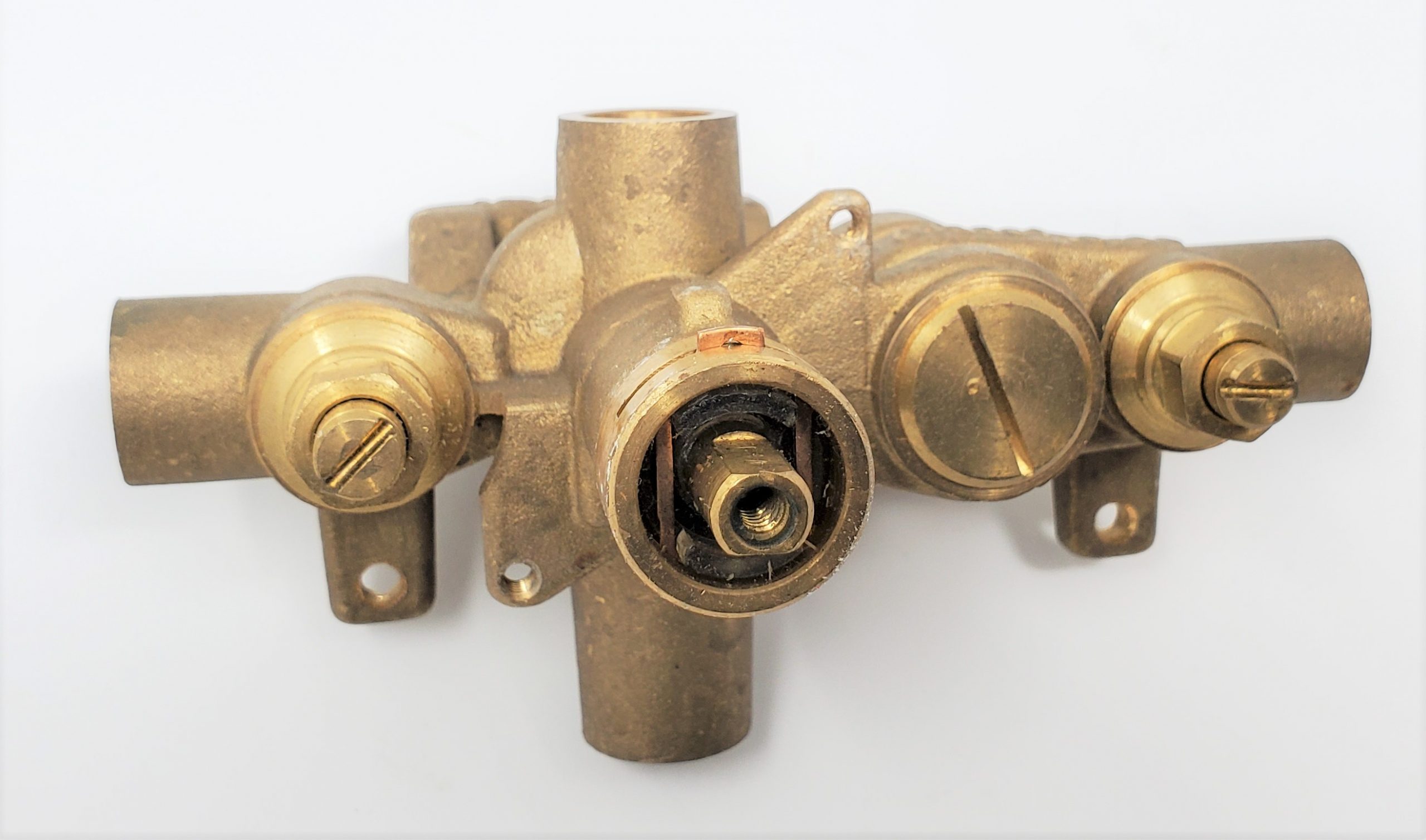
Small meter installation is easier with a meter yoke (also known as a meter setter). Meter yokes have different configurations and can have any combination of built-in check valves, regulators, and lockable shutoff valves. Utilities should have their own set specifications with illustrations depicting proper meter installations.
On all indoor settings, it is very important that electrical continuity be maintained through the waterline. Most utilities require electrical bonding around meters to prevent accidental electrocution of service personnel changing meters. If the meter setting itself does not provide a continuous electrical circuit when the meter is removed, a permanently bonded electrical grounding strap should be provided. Electrical grounding is a requirement specified by the Canadian Electrical Code and all service and installation personnel should be advised of this safety requirement. Most commercially available prepared meter settings provide a continuous metallic circuit, even when the meter is removed from the line.
The Building Water Distribution System
The building water distribution system can be broken into two categories: the cold water distribution system and the hot water distribution system. The design of these systems varies depending on the type of building, size of piping required, and the designer’s preference for piping materials and layouts.
For example, industrial, commercial, and institutional buildings will require more complex water distribution piping arrangements than a single family dwelling. The designer will need to think about pipe sizes while making decisions about materials and layouts. Although any pipe that is listed on the BC Plumbing Code Tables A-2.2.5., 2.2.6. and 2.2.7. under the potable water system above-ground column can be used, smaller diameter piping is typically installed using PEX and copper, while larger diameter piping is typically PVC, CPVC, stainless steel, or polypropylene.
Water Distribution System Layouts
The designs of cold and hot water distribution systems can be quite complex, so some unique terminology is used to help identify different pipes in the system. Some terms are defined in the BC Plumbing Code, but others are colloquialisms of the trade.
Terminology
Main
This term is not defined in the BC Plumbing Code but shows up in the Notes to Part 2 at A-2.6.3.2.(4) and is commonly used by plumbers in the field to describe a larger diameter pipe that supplies several “branches.” The term “trunk” is used by other codes in North America to help identify the “main” pipe in a water distribution system.
Branch
This term is not used in the BC Plumbing Code, but is commonly used by plumbers in the field to describe a pipe that connects to a “main” at the upstream end, and more than one fixture supply pipe on the downstream end.
Fixture supply pipe
This term describes a pipe installed between a fixture and another building water distribution pipe. Although not a defined term in the BC plumbing Code, Table 2.6.3.2.-A uses the term “supply pipe” with the term “fixture,” implying a fixture supply pipe.
Riser
The BC Plumbing Code defines “riser” as a water distribution pipe that extends through at least one full storey. A riser is part of a building water distribution system.
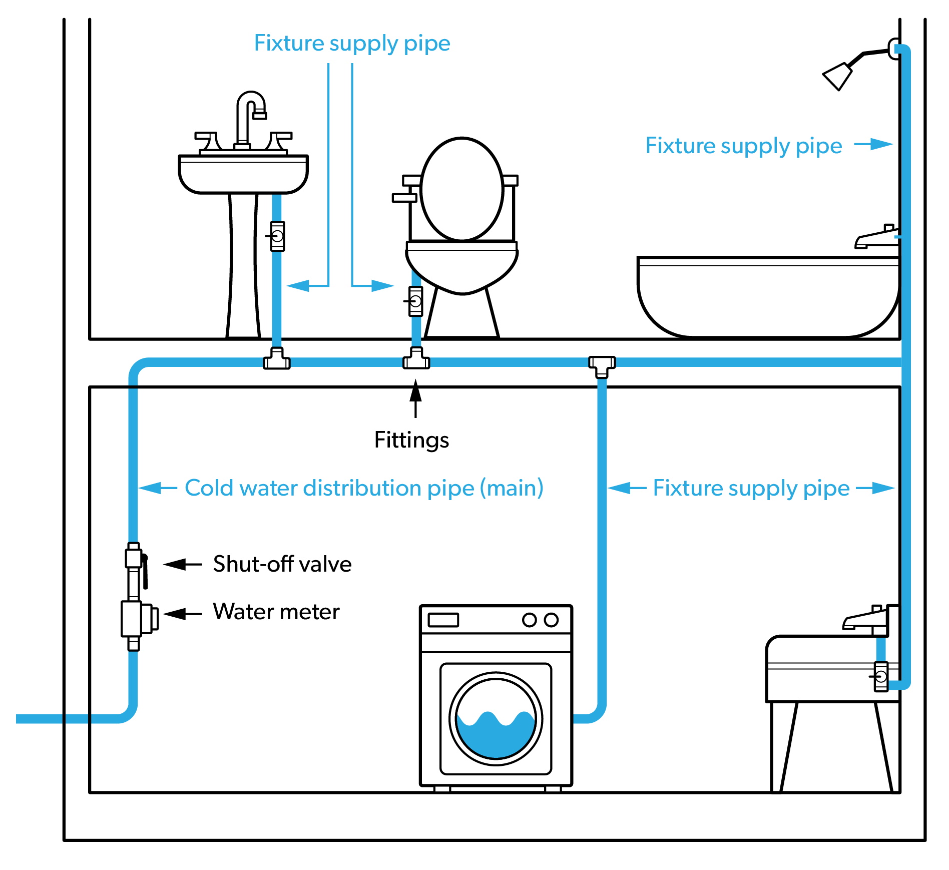
Branch system layout
The branch system layout uses a “main” and “branches”. The main (sometimes called a trunk) is the largest diameter at the upstream end and gets smaller as each branch is connected. This layout is very common for residential and ICI installations using rigid piping materials like copper, PVC, CPVC, stainless steel, and polypropylene. The branch system layout can be used on both cold and hot water distribution systems.
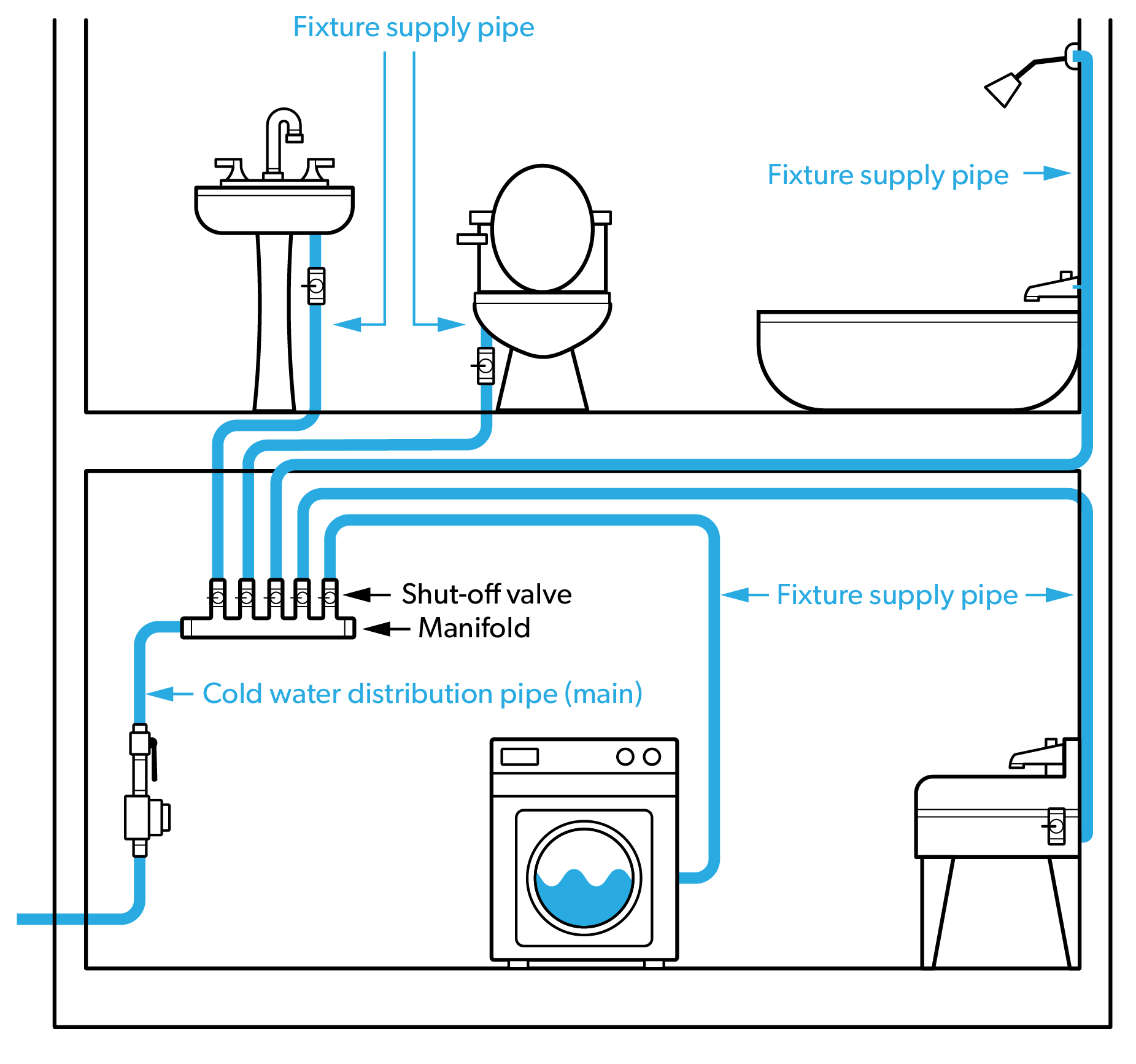
Home-run manifold system layout
The home-run manifold layout is commonly used for residential installations, and can be used on both cold and hot water distribution systems. In this layout, all fixtures are supplied with smaller diameter pipe that is run from the manifold to each fixture. The hot water manifold should be located in close proximity to the hot water source to ensure fast and efficient delivery.
Combination system layout
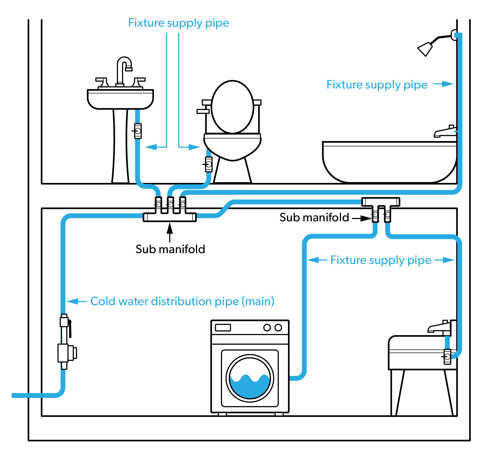
This layout combines properties of the branch system layout with properties of the home-run manifold system layout. Sometimes called the sub-manifold layout, or remote-manifold layout, this design is commonly used in apartment buildings, condominium buildings, and similar buildings that incorporate groups of fixtures. The combination system layout can be used on both cold and hot water distribution systems.
Water distribution systems for tall buildings
Tall buildings, where the height of the building prevents the municipal water from reaching the top floors, require different piping designs and additional components to ensure every fixture has enough water pressure to operate properly. For example, a water service pressure of 80 psi should theoretically be sufficient for an 18 storey building, but there must be sufficient surplus pressure to overcome resistance in riser pipes, as well as approximately 15 psi (105 kPa) to operate most fixtures.
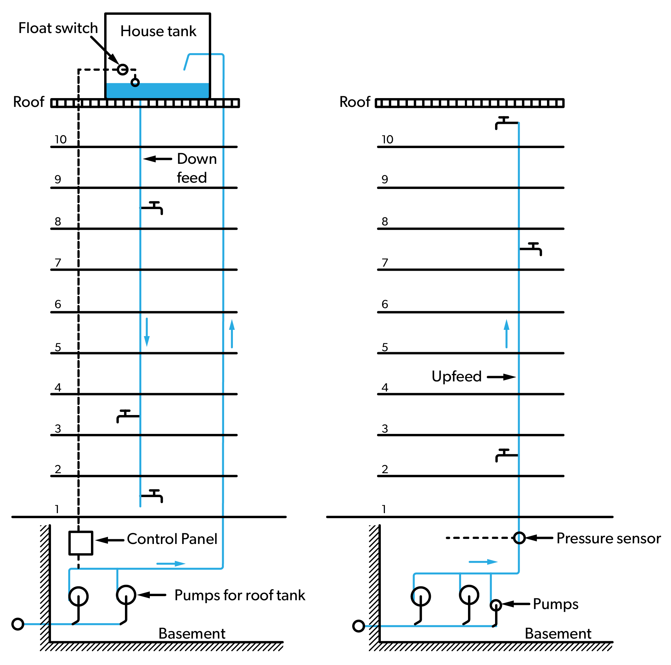
Upfeed booster systems and downfeed booster systems use a pump, or pumps, to boost the pressure of the building’s service pressure. An upfeed booster system uses the additional pressure in the risers to overcome the height, the resistance in the piping, and ensure adequate pressure for the governing fixture on the top storey. This design will usually increase the pressure at lower storeys over the maximum allowable by the BC Plumbing Code. To reduce the pressure at the lower floors, pressure-reducing valves are used on the branches at each storey.
Downfeed booster systems use a pump, or pumps, to boost the pressure of the building’s service pressure and then use this additional pressure to deliver potable water to the roof, or the top storey of the building. Some systems use a storage tank, or tanks, on the roof to create head pressure in the downfeed piping supplying each storey. This design could also increase the pressure at lower storeys over the maximum allowable by the BC Plumbing Code. To reduce the pressure at the lower floors, pressure-reducing valves are used on the branches at each storey.
The figure below shows a simplified downfeed booster system on the left and a simplified upfeed booster system on the right.
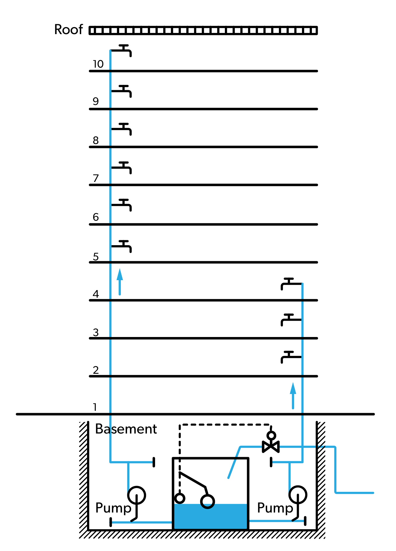
There are variations of both the downfeed and upfeed systems. One variation of the upfeed system, shown in the figure below, would use , where separate pumps are used for different storeys. This design would eliminate the need for pressure-reducing valves but adds complexity to the system.
There are also combination booster designs where the lower part of the building is supplied by the water service pressure, and the storeys above are supplied by a downfeed system.
The variety of water distribution system designs means there are many different components and equipment that could be installed by plumbers as part of cold and hot water distribution systems. Many of these components and equipment are covered below.
Cold Water Building Distribution System
The cold water distribution system begins where the water service pipe ends. In systems where the water meter is outside, the water service ends once the pipe has entered the building. Since the BC Plumbing Code Sentence 2.6.1.3.(1) requires a shut-off valve located as close as possible to where the water service pipe enters the building, the shut-off valve usually indicates the start of the cold water distribution system. If the water meter is installed inside the building, the cold water distribution system would start immediately downstream of the meter location.
Components and equipment
The cold water distribution system incorporates many different types of pipes, fittings, valves, equipment and appurtenances. The BC Plumbing Code prescribes the use of specific materials in some circumstances, but the plumber has a lot of flexibility in selecting most of the other components and equipment that makes up the system. The cold water distribution system can include several unique systems and devices, such as:
- Main shut-off valve
- Fire sprinkler system
- Pressure reducing valve
- Backflow preventer
- Irrigation system
- Exterior hose bibbs
- Water treatment
Some of these components and system connection points are shown on Figure 1, and all of them are covered in the content below.
Main shut-off valve
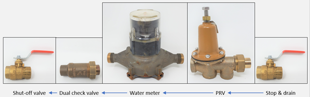
The BC Plumbing Code Sentence 2.6.1.3.(1) requires that water service pipes shall be provided with an accessible shut-off valve located as close as possible to where the water service pipe enters the building. This valve is referred to as the main shut-off and is positioned so it will stop the flow of water to all of the building water distribution system in the event of an emergency. The BC Plumbing Code Sentence 2.6.1.2.(1) also states that a water distribution system shall be installed so that the system can be drained or blown out with air. These two Sentences in the BC Plumbing Code combine to mean that a stop-and-drain (also called a stop-and-waste) shut-off valve is usually installed on the residential water service pipe.
A 1 inch (25 mm) water service is permitted to have a stop-and-drain valve as the shut off valve for the building. When the water service pipe size increases to 1-1/4 inch (approximately 32mm), the shut off valve for the building must be a shut off valve only. A separate drain valve is placed downstream of the meter to allow the meter set and building distribution system to be drained. Any faucets or equipment that are placed on the building distribution system to allow the system to function properly must be accessible for servicing or repair of the components. Accessibility must be considered in system design to minimize disruption of the living space. As the building distribution system is installed, it may be necessary to place portions of the pipe under beams, air ducts or other obstructions. Any low points in the building distribution system that do not drain by gravity should include drain valves as part of the low point piping.
Residential combined (multipurpose) fire sprinkler systems
These systems integrate with the cold water distribution system, with the sprinklers fed off of the same water source as the other fixtures in the home. Because they use the same pipes and fewer fittings and connections, the installation costs and complexity tend to be less with combined systems. Combined systems may not be an option for homeowners who are looking to retrofit sprinklers into their house, as these systems require carefully planned hydraulic calculations that account for water pressure, the size of the system, and even the diameter of piping needed to meet specific flow requirements.
Two types of combined fire sprinkler systems are defined in the BC Plumbing Code.
- Residential full flow-through fire sprinkler/standpipe system means an assembly of pipes and fittings installed in a one- or two-family dwelling that conveys water from the water service pipe to the sprinkler/standpipe system’s outlets and is fully integrated into the potable water system to ensure a regular flow of water through all parts of both systems.
- Residential partial flow-through fire sprinkler/standpipe system means an assembly of pipes and fittings installed in a one- or two-family dwelling that conveys water from the water service pipe to the sprinkler/standpipe system’s outlets and in which flow, during inactive periods of the sprinkler/standpipe system, occurs only through the main header to the water closet located at the farthest point of the two systems.
For combined, multipurpose systems, a water meter is used. This means the designer must include the water meter in the hydraulic calculations when sizing the system.
Residential standalone fire sprinkler systems
This design uses a network of piping that is separate from the piping used in the water distribution system. Both the standalone sprinkler and building water supply systems can draw from the same water supply, or a standalone system can draw from its own supply, such as a dedicated water tank. If the standalone system uses the same water supply as the building, it is generally connected upstream of the water meter. The National Fire Protection Association (NFPA) Standard 13D is referenced in the BC Building Code as the standard for installation of sprinkler systems in one- and two-family dwellings and manufactured homes. The NFPA 13D standard recommends that a water meter not be installed on the sprinkler line because the meter could produce friction or blockage or reduce water pressure.
In jurisdictions that require meters on standalone systems, the meter is placed before the tee between the domestic and sprinkler lines. In these cases, the meter must be included in the hydraulic calculations for the sprinkler system.
If the residential standalone system design incorporates fewer than nine sprinklers, the BC Building Code Sentence 3.2.5.12.(4) allows the water supply for these sprinklers to be supplied from the domestic water system for the building provided the required flow for the sprinklers can be met by the domestic system. This means the plumber would not have to allow for the fixture unit load when calculating the water service pipe size.
There are two classes of fire sprinkler systems used for residential applications:
- Class 1 Fire sprinkler/standpipe system means an assembly of pipe and fittings that conveys water from the water service pipe to the fire system outlets that has direct connections only from public water mains and has no pumps, tanks, or reservoirs and all sprinkler drains discharging to atmosphere, dry wells or other safe outlets.
- Class 2 Fire sprinkler/standpipe system means an assembly of pipe and fittings that conveys water from the water service pipe to the fire system outlets that is the same as a Class 1 Fire sprinkler/standpipe system and that also includes a booster pump in the connection from the street mains.
The figure below shows the preferred connection method for a standalone residential fire sprinkler system using the building water service pipe as the supply.
Pressure-reducing valves
As mentioned in Competency B1, pressure-reducing valves are used for many plumbing system applications in both residential and ICI applications. PRVs installed in buildings are used reduce high municipal main pressure to an acceptable operating range for use in the water distribution system. The BCPC Article 2.6.3.3 states that where the static pressure at any fixture may exceed 550 kPa, a pressure-reducing valve shall be installed to limit the maximum static pressure at the fixture to 550 kPa.
Backflow preventer
A backflow preventer is typically found on a water supply service to a building, as well as in many locations inside buildings on the water distribution system.
As mentioned in Competency B1, cross connection control and backflow prevention devices are covered in detail in Block C section of the Level 3 content.
Hose bibbs
All buildings need water supplied to the outdoors for many reasons. These exterior, or outdoor, hose bibbs are commonly referred to as wall hydrants and have been traditionally supplied by only cold water. Since any exterior water supply must be protected, the BCPC Article 2.6.1.4. allows two methods of installation to prevent freezing during the colder months.
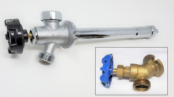
The frost-proof hydrant is designed so that the water supply to the faucet is shut off inside the building, where it is heated. Sloping the barrel to the outside during installation will ensure the water drains from the barrel and will prevent freezing of the water in the hydrant. It is important that the garden hose or any attachments placed on the hydrant for connection of a hose or other accessory are removed to ensure that the barrel of the frost-proof hydrant drains completely in cold weather. Frost-proof hydrants are available in a variety of lengths to accommodate most building construction methods.
Another method of installation to prevent a hose bibb from freezing is to install a stop-and-drain (also called a stop-and-waste) valve on the supply piping leading to the exterior. The drain or waste outlet on the valve will need to be opened once the valve has been closed for the season. The hose bibb should be opened to allow any water trapped in the supply piping to drain or allow air into the piping to permit water to drain through the hose bibb. It is important that the stop-and-drain valve be installed in the right direction; otherwise, the piping to the exterior cannot be drained.
Hose bibbs are also available as hot and cold units if homeowners or businesses require tempered water outdoors.
Irrigation connection
Connections to the building water supply system for irrigation systems is common for residential and ICI buildings. For ICI buildings, the irrigation system designer will need to provide the water supply system designer with load requirements so the water service pipe can be sized correctly. When residential irrigation systems are added to an existing building, it is common for the designer to calculate the irrigation system’s maximum available flow for each zone based on the existing water service pipe size and the water meter size. For irrigation systems installed with new residential construction, the irrigation system designer needs to provide the plumber with the calculated demand flow. Section 2.6 of the BC Plumbing Code requires that the fixture units for irrigation system be added to the water service sizing.
Residential irrigation systems are described in more detail in the Plumber level 3 Competency B3.
Water treatment equipment
As discussed in Competency B1, almost all domestic water goes through some form of treatment before being delivered to the end user. Water purveyors must treat the raw source water to ensure it meets the requirements of the Drinking Water Protection Act and Drinking Water Protection Regulation, as well as the conditions set on their operating permits. There are times when the potable water delivered to the end-user meets the minimum requirements, but still requires further treatment. Conditions such as hard water and aesthetically-displeasing water may require the use of water treatment equipment that is installed in the building by the owner.
Residential and small commercial water treatment systems, such as whole-system water softeners and point-of-use water purification equipment, are generally selected and installed by plumbers. Larger and/or more complex water treatment systems are more likely to be designed by specialists, such as engineers. Private water supply systems regularly require the use of water treatment equipment to ensure it meets the requirements for domestic use. For example, if you are the owner of a well that only supplies water to one connection (e.g. a private household), you are responsible for testing your water to determine if it is safe for you and your family to drink. Water samples should be sent to a qualified laboratory for testing. Be aware that test results will only tell you about the water quality on the day you test it, as well water quality can change over time. Weather, seasons, drought, floods or other events may cause contamination. It is recommended well-users test for water quality after significant weather events and, once a year, see if water quality has become a problem.
The water treatment equipment used for single-family dwellings is covered in the Level 4 content of the plumber program.
Hot Water Building Water Distribution System
A hot water supply is required by the BC Building Code for every dwelling unit, and for every building where a water closet and lavatory are mandatory. The hot water distribution system starts at the service water heater.
A brief history of water heating
From the Roman bathhouses to modern day fixtures and appliances, hot water seems essential to every person. However, what most us now take for granted—clean, hot running water at the turn of a faucet—was not available in much of North America only a couple of generations ago. It still isn’t available in many parts of the underdeveloped world.
Water heated on open fireplaces gave way to wood and coal-fired stoves for heating and cooking. Pipes carrying hot water from elevated tanks to fixtures in the building replaced the need for carrying buckets of hot water. The evolution of the hot water distribution system continued with the invention of electric and gas-fired storage-type service water heaters. The modern tankless service water heater continues the evolution of the domestic water heating appliance.
Components and equipment
Just like the cold water distribution system, the hot water distribution system also incorporates many different types of pipes, fittings, valves, equipment and appurtenances. The hot water distribution system can include several unique systems and devices, such as:
- Service water heaters, and associated appurtenances
- Mixing valves (Tempering valves)
- Thermal expansion protection devices
- Hot water recirculation systems
These components and system connection points are covered in the content below.
Service water heater types
The BC Plumbing Code defines a “service water heater” as meaning a device for heating water for plumbing services. The service water heater is the domestic water heating source and can be one of several different appliances. The different appliance types can be categorized by the method of heat development, either direct heating or indirect heating, as well as by the location in the system, either point-of-distribution or point-of-use.
- Direct heating - heat from the combustion of fuels, collection of solar energy, or direct conversion of electrical energy into heat applied directly in water heating equipment.
- Indirect heating - heat energy developed from remote heat sources such as boilers, solar, cogeneration, refrigeration, waste heat, etc. and then transferred to the water.
- Point-of-distribution - water heaters that serve the entire domestic hot water distribution system. The term “central water heater” is also used to describe this type of water heater.
- Point-of-use - water heaters designed to deliver hot water almost instantaneously, and are installed at the location of the fixture or appliance requiring the hot water.
The most common designs for service water heaters are listed here:
- Indirect service water heaters
- Tankless (on-demand, instantaneous) water heaters
- Storage-type (tank-type) water heaters (electric, gas, heat pump, etc.)
- Point-of-use water heaters (electric, steam, etc.)
The water heaters listed here are described in the content below.
Indirect service water heaters
The BC Plumbing Code defines an “Indirect service water heater” as a service water heater that derives its heat from a heating medium such as warm air, steam or hot water.
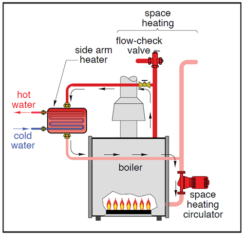
There are several variations of indirect heating of the domestic water. In most indirect water heaters, hot water from a heat source flows through one side of a heat exchanger while potable water flows through the other side. Systems that incorporate domestic water heating into a space heating system are referred to as combined systems. The figure below shows a hydronic heating boiler as the heat source for space heating as well as providing heat for domestic hot water through a heat exchanger.
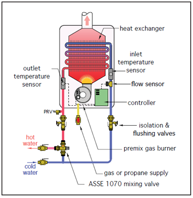
Tankless (on-demand, instantaneous) water heaters
A tankless water heater is a direct heating appliance that heats water almost instantaneously without the use of a storage tank. When a hot water faucet is turned on, and a minimum flow is detected by the controls, either a natural gas burner or an electric element heats the water as it flows through a heat exchanger in the unit. Both the electric model and the gas-fired model have large energy inputs so, given this relatively high rate of heat generation, the heat exchanger warms quickly. Tankless water heaters are available in a wide range of capacities for both residential and commercial applications.
Storage-type (tank-type) water heaters
Storage-type water heaters, also referred to as tank-type water heaters or simply hot water tanks, are the dominant design of domestic water heater installed in residential and commercial buildings. This section will go into more detail on the storage-type water heater since the water distribution system sizing drawings used in this Block incorporate this design.
Electric tank-type water heaters
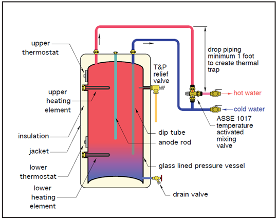
One of the most common devices used in residential and light commercial buildings is a tank-type electric water heater. Most tank-type electric water heaters have a welded steel pressure vessel surrounded by an insulated jacket. The space between the pressure vessel and jacket is filled with fiberglass or foam insulation. The higher the R-value of this insulation, the lower the standby heat loss from the tank.
Storage-type service water heaters are shipped with several components already installed. The content below describes most of these components.
Heating elements
Almost all tank-type electric water heaters sold today are designed to use immersion-type heating elements. The number of elements that are installed by the manufacturer depend on the tank size and the recovery rate required by the system design. It is important when replacing an element to ensure the new element matches the old element, as there are different lengths, different mounting designs, different voltages, and different wattages.
For example, a 40 US gallon residential tank would typically use two 240-volt, single-phase, 4-bolt, 3000-Watt elements while a large volume electric commercial tank might require five 208-volt, 3-phase, threaded, 4000-Watt elements.
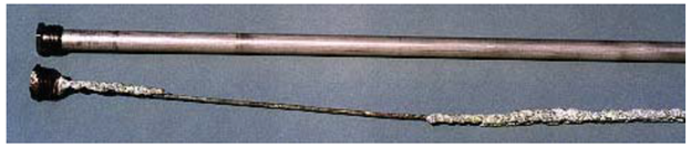
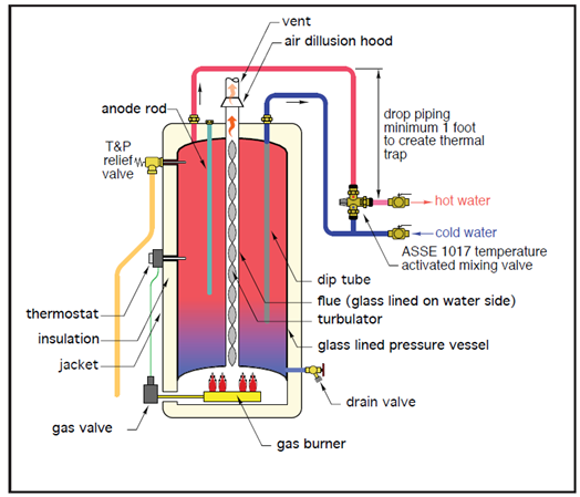
Anode rod
The inner surfaces of the steel pressure vessel are coated with a heat-fused vitreous material often referred to as “glass lining”. Its purpose is to isolate the steel tank surfaces from the corrosive effects of water. Although this glass lining covers the majority of the inner tank surfaces, there are small areas that may not be coated. To protect these exposed steel areas against corrosion, most tank-type water heaters are supplied with one or more anode rods, which are screwed into ports at the top of the tank. Anode rods are made of either aluminum or magnesium. These metals are less noble on the galvanic scale compared to steel. As such, they serve as the preferred corrosion surface (rather than the exposed steel within the tank). Over time, anode rods are consumed, or sacrificed, by this corrosion process and need to be replaced to extend the life of the water heater. Hence the term “sacrificial anode” commonly used in the plumbing trade.
The lifespan of steel tanks will vary based on many factors, but the warranty on the tank is based on the number of anodes. A tank with a single anode is typically warrantied for six years, while a tank with two anodes could have a warranty up to twelve years. There are non-metallic electric water heaters available that are impervious to rust and corrosion, removing the need for an anode rod. These tanks typically have a lifetime warranty.
Dip tube
Tank-type water heaters also contain a dip tube. Its purpose is to deliver cold water near the bottom of the tank, thus preserving temperature stratification within the tank (e.g., hottest water at the top and coldest water at the bottom).
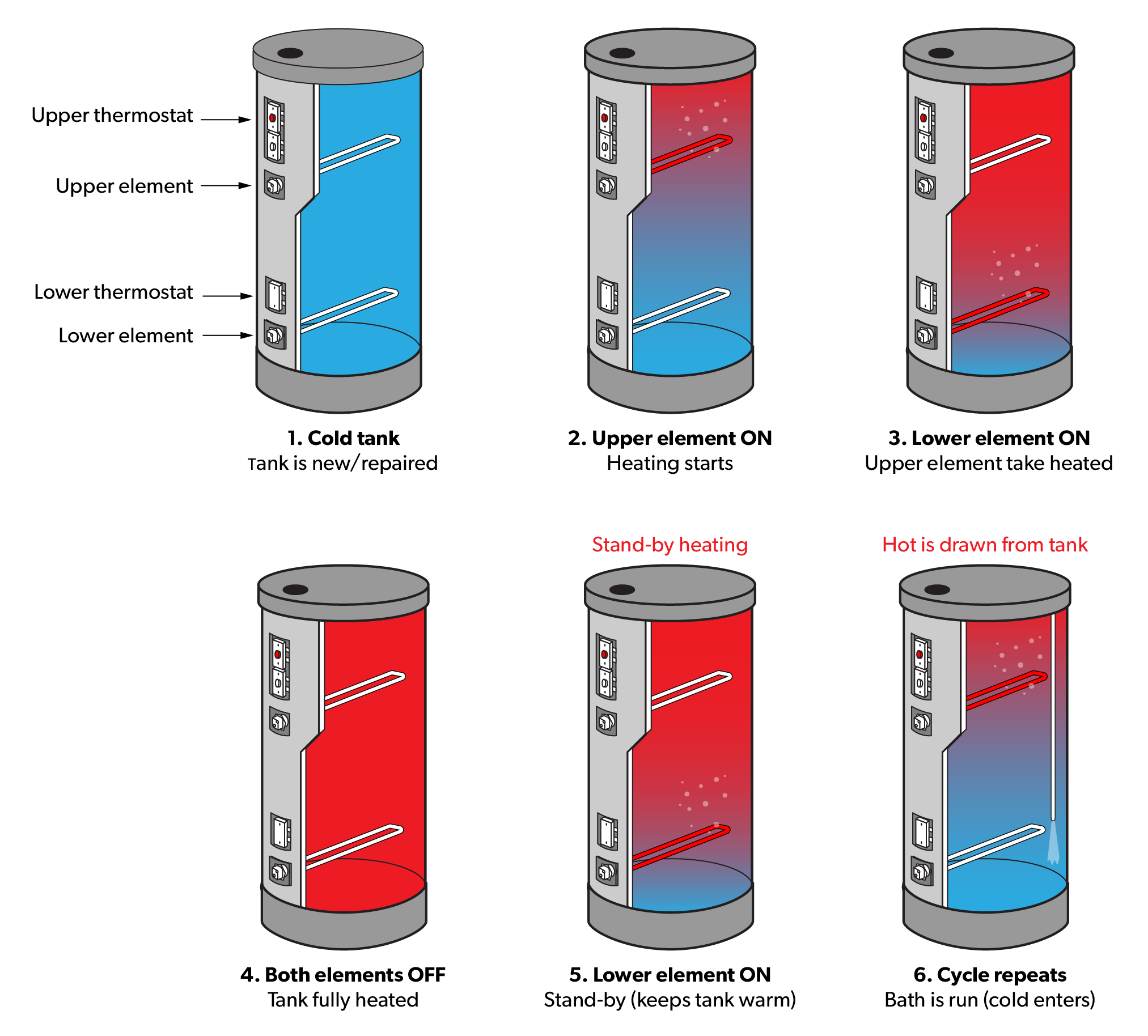
An electric tank-type water heater that is sized to cover all the water heating needs of an average single family home will usually range in size from 30 to 119 gallons. It will have two electric heating elements, one in the lower portion of the tank and the other near the top of the tank.
In residential applications, these elements are powered by a 240 VAC circuit and have heating outputs ranging from 3.8 to 6.0 kW (approximately 13,000 to 20,500 Btu/hr). Under normal operating conditions, the lower element provides the heating. It is turned on and off by a line voltage thermostat built into the tank. During periods of high demand, the water temperature near the top of the tank may drop several degrees. When this occurs, the lower heating element is turned off and the upper element is turned on. This concentrates heat input where water is leaving the tank. The objective is to sustain acceptable water temperature to the fixtures during high demand. When demand lessens and the upper tank thermostat is satisfied, the lower element resumes heating under the control of the lower tank thermostat.
The figure below shows the cycling of the two elements in a tank-type electric water heater.
Relief valve
Water that is enclosed in a container expands when heated. If the heat is not controlled, excessive temperature and pressure can build up to the bursting point. To eliminate this hazard, a temperature and pressure relief valve is installed on all hot water tanks and direct the outlet to within 12 inches of the floor. The pressure portion of the temperature and pressure valve relieves excess pressure, while the temperature-relief valve prevents overheating the unit. This valve is normally a thermal expansion type.
Before activating any service hot water tank, make absolutely sure it is full of water. A simple method of purging air from the hot water tank is to open a hot water faucet and allow the air to escape while the tank is filling. A constant flow of water from the hot water faucet indicates that all the air has been expelled from the hot water tank.
The BC Plumbing Code Article 2.6.1.7. includes several Clauses that cover the requirements for relief valves on service water heaters.
Gas-fired tank-type water heaters
Another very common tank-type water heater is a gas-fired model fueled by either natural gas or propane. This model of service water heater incorporates many of the same components as the electric model. These tanks will be covered in more detail in the Gasfitter portion of the program.
Service water heater start-up, commissioning, service, and maintenance
Service water heater start-up, commissioning, service, and maintenance will be covered in the plumber level 4 content.
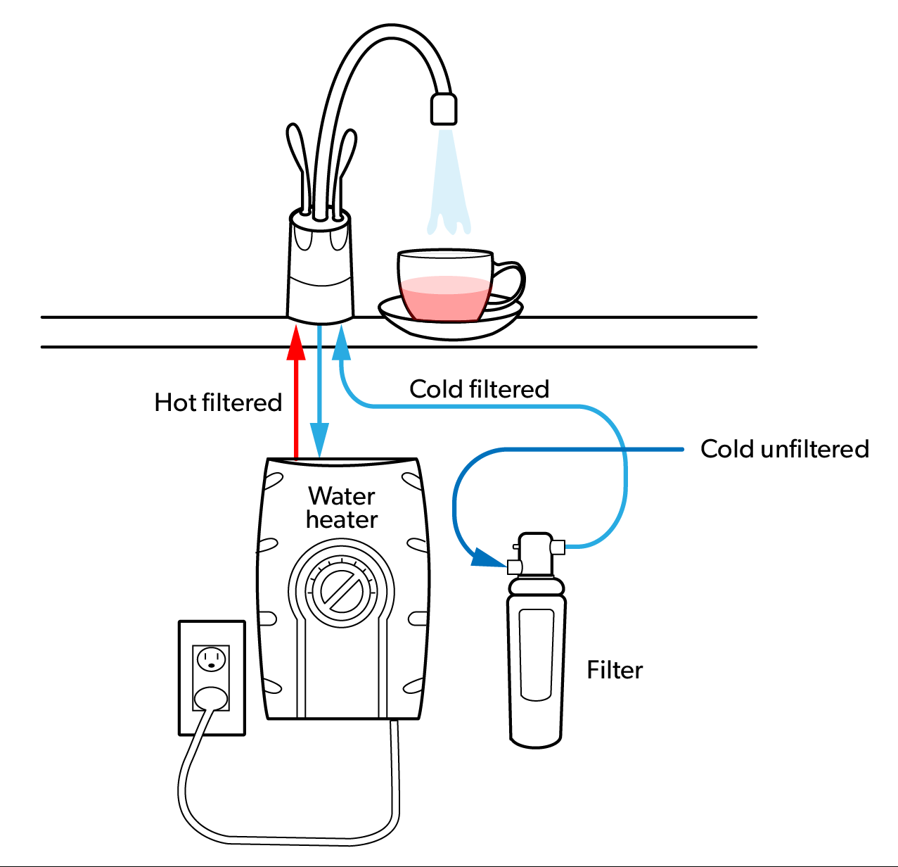
Point-of-use water heaters
These types of water heaters are commonly referred to as “booster heaters”. In North America, they are generally installed as a booster for commercial dishwashing to ensure the minimum final rinse temperature of 180 degrees F (82 degrees C) is reached. Some models are compact enough to be installed under sinks and remote locations for use as booster heaters for users to have instant hot water. These types of water heaters are typically electric and have a small reservoir of heated water ready for use at all times.
The figure below shows an electric point-of-use water heater installed at a kitchen sink.
Advantages and disadvantages of different water heater designs
Storage-type water heaters are still the most popular type of domestic and commercial water heaters being installed. One disadvantage to a storage-type water heater is the size of the tank. Higher demand for hot water generally means a larger tank. Electric hot water tanks have the advantage of being the lowest cost heater design, and can be installed in more locations than a gas-fired hot water tank because they don’t require a vent. Electric hot water tanks tend to be quieter when operating as there is no gas burner noise. Electric hot water tanks are also very efficient, although this may not mean the annual operating cost is lower than other designs as the cost of electricity may be higher in some regions than the cost of fuel gas. One disadvantage of electric hot water tanks is that they may not recover as fast as gas-fired hot water tanks. Recovery rate is covered in the “Sizing service water heaters” content later in the Competency.
Tankless designs are very popular for new construction and are considered to be one of the most economical designs of domestic water heating, as there is no water being stored so there is no standby heat loss. They are smaller than storage-type water heaters and are wall-mounted, requiring very little floor space. [JG1] Their size can make them particularly attractive in homes where square footage is at a premium. The on-demand design means that, if sized correctly, these heaters can provide a continuous supply of hot water. One disadvantage of tankless water heaters is the large energy input required for on-demand water heating. The electric version creates a significant amperage draw when in use, so this must be accommodated in the electrical service size. Gas-fired versions have burners several times larger than a storage-type water heater, so retrofitting may mean a gas piping revision. The gas-fired version also needs a vent to outdoors, which may restrict the locations it can be installed in the building. The large energy input of both designs causes some precipitation of the mineral in the water and frequent maintenance may be required. It is important that these heaters have a supply of high-quality potable water to ensure a long life. Tankless water heaters have been known to create a “cold-water sandwich effect”, which is the undesired introduction of cold water into the hot water supply line on occasions of frequent on/off operations. Most manufacturers have now resolved this issue.
Indirect water heaters are typically used when there is a heat source installed for another purpose. These designs often combine space heating with domestic water heating, so can be referred to as combination systems. The advantage of this design is the initial cost savings. For example, using a hydronic heating boiler as the heat source means the tank is only for hot water storage and does not require its own heat source. This involves less maintenance and potentially a lower annual operating cost. The disadvantage of this design is that a storage tank is still required, so space must be found for it. This design also needs to be controlled correctly so that the customer can maintain indoor temperature as well as meet the domestic water heating load. Some consideration must be taken if a combination system is installed in a region where there is no need for space heating during the summer months. This would require the boiler to operate solely to supply hot water, which would lower the efficiency of the system.
There may be an advantage to having a pre-heat system installed for the service water heater. If the inlet water temperature is raised by a pre-heat system, then the service water heater operates less, which theoretically lowers the annual operating cost. Care must be taken by the designer to ensure the pre-heat system does not jeopardize the potable water quality or create a complex system that could interrupt the domestic hot water supply if it failed. One pre-heat system that has been used extensively in British Columbia is the solar domestic hot water pre-heat system.
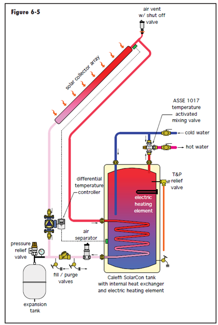
Solar domestic hot water pre-heat system
Solar energy can be used to heat water when the right conditions are met. A building with suitable amounts of south-facing roof or walls can have solar collectors installed and transfer the water heated in the panels to a storage system in the building. In the system shown below, heated water from the solar storage tank is routed through a heat exchanger of an electric water heater, where its temperature is increased to the desired setpoint (when necessary). A thermostatic mixing valve on the outlet of this water heater prevents high temperature water from reaching the building’s fixtures. High water temperatures are possible in almost any type of solar water heating system during prolonged sunny weather, especially if hot water demand is low.
Tank-type water heaters are typically used as “finishing” heaters to boost the temperature from the solar water heating system to the desired outlet temperature. Tankless water heaters are not typically used because the controls in some tankless heaters will not allow the unit to come on if the thermal load is less than the minimum heat transfer rate for the appliance. The controls constantly monitor the flow rate and inlet water temperature, and then use this information along with the unit’s setpoint temperature to determine the thermal load on the heater and compare it to the heater’s minimum heat transfer rate. For example, if the water temperature from the solar water heating system is too close to the setpoint, the unit may not come on.
Plumbers can design and install solar pre-heat systems, but the BC Plumbing Code Article 2.6.1.8. states that systems for solar heating of potable water shall be installed in conformance with CAN/CSA-F383, Installation of Packaged Solar Domestic Hot Water Systems.
Service water heater efficiency
The BC Building Code Article 9.36.4.2. addresses equipment efficiency standards for service water heaters, listing the performance requirements on Table 9.36.4.2. For example, while electric water heater efficiency typically approaches 100%, a gas-fired tankless service water heater must be a minimum of 80% efficient.
Service water heater temperature setpoint
There is a lot of debate over the best hot water heater temperature setpoint. Safe storage and distribution of domestic hot water is imperative in any application. Storing water at temperatures high enough to eliminate bacteria, but delivering hot water at temperatures safe for use by all users, has been a challenge for plumbers. To help guide plumbers, the BC Plumbing Code has added the following information at Notes to Part 2 A-2.6.1.12.(1):
Service Water Heaters. Storing hot water at temperatures below 60°C in the hot water tank or in the delivery system may lead to the growth of legionella bacteria. Contemporary electric water heater tanks experience temperature stratification and thus tend to have legionella bacteria in the lower parts of the tank. Article 2.6.1.12. specifies a thermostat setting of 60°C (140°F), which addresses the concern over the growth of legionella bacteria in electric hot water storage tanks and is enforceable without introducing unnecessary complications. The growth of legionella bacteria is not a concern for other types of water heaters with different designs that use different fuels. Electrically heated water heaters are shipped with the thermostat set at 60°C (140°F). Article 2.6.1.12. is included in this Code to formalize this de facto temperature setting as a requirement. The thermostats have graduated temperature markings to allow such a setting, which is not the case with gas- or oil-heated water heaters.
The figure below shows the relationship between the status of Legionella bacteria and the temperature of the water in which they exist.
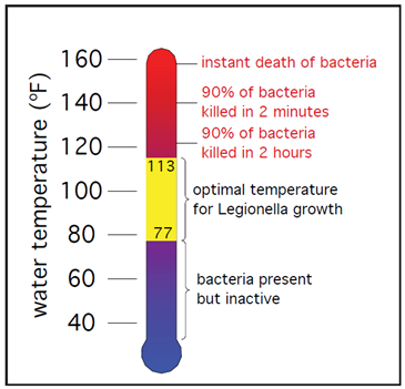
The information on service water heater settings addresses the temperature requirements for hot water storage but does not address the recommended hot water delivery temperature. The ideal temperature setting for a service water heater requires the plumber to consider many factors. The BCPC guides plumbers with Article 2.2.10.7 by prescribing a maximum water outlet temperature for showers and bathtubs as 49°C (120°F). This maximum temperature setting is to minimize the possibility of a scald or thermal shock to the user, and would require the use of a mixing valve in many applications, especially if using an electric storage-type water heater. Since modern shower and bathtub valves are typically one-handle, pressure balanced/thermostatic type, and have an integrated maximum temperature stop, these valves can be set up by the plumber to meet the 49°C maximum setpoint. The BC Plumbing Code provides additional information on hot water temperature setpoints at Notes to Part 2 A-2.2.10.7:
Hot Water Temperature. Hot water delivered at 60°C (140°F) will severely burn human skin in 1 to 5 seconds. At 49°C (120°F), the time for a full thickness scald burn to occur is 10 minutes. Children, the elderly and persons with disabilities are particularly at risk of scald burns. Compliance with Article 2.2.10.7. will reduce the risk of scalding in showers and bathtubs, and reduce the risk of thermal shock from wall-mounted shower heads.
These requirements apply to all occupancies, not just residential occupancies.
The water outlet temperature at other fixtures, such as lavatories, sinks, laundry trays or bidets, is not addressed by Article 2.2.10.7., but a scald risk may exist at such fixtures nonetheless.
Service water heater sizing
Determining the correct water heater size is a critical step in the design of a hot water distribution system. Fortunately, water heaters are produced in a wide variety of designs and sizes to help designers select the best model for their specific application.
Selecting a service water heater for a residential building is much simpler than determining the service water heating system for ICI buildings. Since both tank-type and tankless water heaters are common for residential and ICI applications, the sizing methods will be covered separately as follows:
- Residential tank-type water heater sizing
- Residential tankless water heater sizing
- ICI tank-type water heater sizing
- ICI tankless water heater sizing
Residential tank-type water heater sizing
There are essentially two methods used to size residential service water heaters. The designer can go through the sizing process using a worksheet and decide based on the results, or the designer can use online sizing tools that most manufacturers provide. For both methods, the designer will need to collect accurate information about the domestic hot water system and the customer’s needs.
Worksheet method for storage-type tank size selection.
| Use | Average gallons of hot water per usage | × | Times used during 1 hour | = | Gallons used in 1 hour |
|---|---|---|---|---|---|
| Shower | 20 | × | = | ||
| Shaving | 2 | × | = | ||
| Automatic dishwasher | 7 | × | = | ||
| Hand dishwashing or food prep | 3 | × | = | ||
| Clothes washer - Top-load model | 25 | × | = | ||
| Clothes washer -Front-load model | 15 | × | = |
Total peak hour demand =
The worksheet shown above uses “peak hour demand.” This is an estimate of the customer’s maximum usage of hot water during a one-hour period of the day. For some residential applications, this is in the morning when everyone is getting ready for work or school; for other applications, this may be in the evening, when dishes are getting done and people are showering, etc. Some manufacturers’ water heater sizing calculations use a two-hour peak usage period while others use one hour or even 30 minutes.
Once the designer has estimated the total peak hour demand, the tank-type water heater can be selected based on the first hour rating. The first hour rating is the number of gallons of hot water the heater can supply per hour (starting with a tank full of hot water). It depends on the tank capacity, source of heat (burner or element), and the size of the burner or element. The rating can be found on manufacturers’ websites in the specific literature for each tank. The designer would look for water heater models with a first hour rating that at least matches the application’s requirements.
An example of product specifications for a 40 gallon electric hot water tank are shown on the chart below. The first hour rating is the last row on the chart.
| Nominal Capacity | 40 |
|---|---|
| Rated Storage Volume | 36 |
| UEF | 0.92 |
| Recovery Gallons | 25 |
| Power Source | Electric |
| Limited Tank Warranty | 9 Years |
| Limited Parts Warranty | 9 Years |
| Anode | Alum |
| Water Connection Location | Top |
| Water Connection Size | ¾″ |
| First Hour Rating | 50 |
Note: when a large capacity bathtub (such as a whirlpool tub) is part of the home equipment, it is important that the water heater first hour rating be capable of filling the tub. This may mean the tank-type water heater size is increased just to meet this special demand.
Online sizing tool method for storage-type tank size selection
For the selection of residential tank-type water heaters using a manufacturers online sizing tool, the designer typically needs to answer a series of questions, such as:
- What is the length of the longest shower someone takes?
- How many showers would your household like to take back-to-back?
- How many showers would your household like to take at the same time?
- What size is the largest bathtub?
- Do any of the showers have body sprays or multiple/high flow heads?
- How would you like to heat your water?
- How much space do you have?
Once the questions have been answered, the sizing tool will give the designer several options to choose from.
Residential tankless water heater sizing
Tankless or on-demand type water heaters are rated by the maximum temperature rise possible at a given flow rate. To determine temperature rise, subtract the coldest incoming water temperature from the desired outlet temperature. An example for British Columbia would be 140°F (desired outlet temperature) minus 40°F (cold water temperature in the service pipe in winter) equals 100°F temperature rise.
Flow rate can be calculated by adding up the individual flow rates for all the hot water devices that are expected to operate at any one time during the peak usage period. For example, if the two fixtures that will use hot water simultaneously are a hot water faucet with a flow rate of 0.75 US gallons (2.84 liters) per minute and a shower head with a flow rate of 2.5 US gallons (9.46 liters) per minute, then the desired flow rate required for the on-demand water heater would be 3.25 US gallons per minute (12.3 liters per minute). It is possible to estimate flow rate by holding a bucket under the faucet or shower head and measuring the flow for one minute.
Once the temperature rise and flow rate have been determined, the designer can use a manufacturer’s sizing chart to select a model that will meet the needs of the customer. An example of a sizing chart is shown below. If a model can not be determined because of excessive flow rate, the designer may need to suggest the homeowner install low-flow fixtures.
| Temp rise (°F) | Model 150 GPM | Model 180 GPM | Model 210 GPM | Model 240 GPM | Model 270 GPM |
|---|---|---|---|---|---|
| 30 | 6.8 | 8.4 | 10.1 | 11.1 | 11.9 |
| 40 | 5.9 | 7.3 | 8.7 | 9.7 | 10.6 |
| 50 | 4.7 | 5.8 | 7.0 | 7.8 | 8.6 |
| 60 | 3.9 | 4.9 | 5.8 | 6.5 | 7.1 |
| 70 | 3.4 | 4.2 | 5.0 | 5.5 | 5.9 |
| 80 | 2.9 | 3.6 | 4.4 | 4.8 | 5.1 |
| 90 | 2.6 | 3.2 | 3.9 | 4.3 | 4.6 |
| 100 | 2.4 | 2.9 | 3.5 | 3.9 | 4.2 |
| 110 | 2.1 | 2.6 | 3.2 | 3.5 | 3.7 |
| 120 | 2.0 | 2.4 | 2.9 | 3.2 | 3.4 |
Manufacturers’ online sizing tools are also available for selecting tankless water heaters.
ICI tank-type water heater sizing
Industrial, commercial, and institutional (ICI) hot water demands vary significantly based on the building’s designated usage. The designer needs to determine the building usage before sizing the service water heater. The list below shows the most common designations for ICI buildings:
- Apartment
- Hotel/motel
- Dormitory
- School
- Restaurant/food service
- Office building
- Hospital/nursing home
- Prison
- Industrial plant
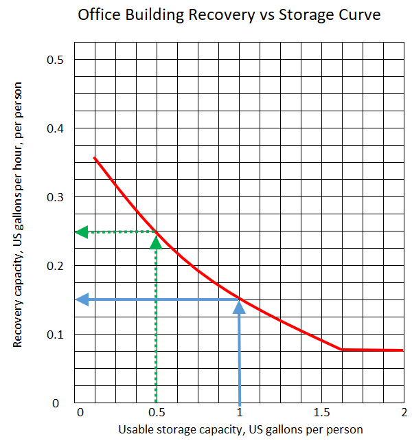
Once the building designation has been decided, the recovery capacity and usable storage capacity for the tank-type heater needs to be calculated. A graph from the manufacturer that plots recovery capacity versus usable storage capacity can be used to estimate the water heater parameters for the application. For example, using the figure below, if 100 people were in an office building at peak demand time, the solid arrows show that a water heater could be selected that has 100 US gallons of usable storage capacity (1 US gallon per person x 100 people) as long as it could recover 15 US gallons per hour (0.15 USGPH per person × 100 people). Alternatively, the dashed arrows show that a smaller 50 US gallon water heater could be used as long as it could recover 25 US gallons per hour.
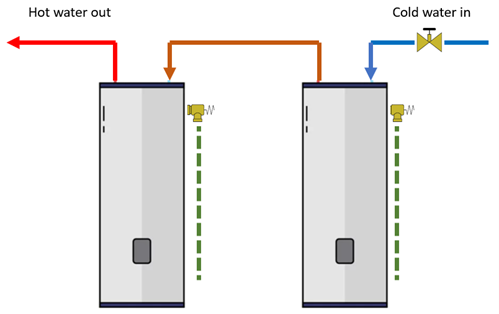
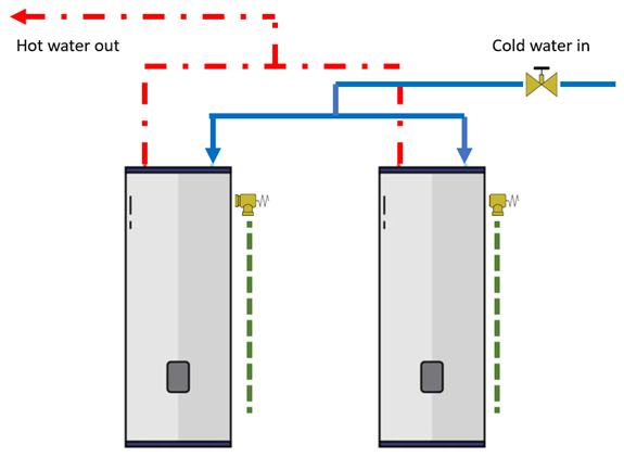
Manufacturers’ online sizing tools are also available for ICI applications. Similar to the residential version, the designer goes through a series of questions, inputting accurate data to get several options for water heater choices. One of the questions that gets asked is about the number of water heaters the designer plans to use. For larger ICI applications, more than one tank-type water heater may be required to meet the peak demand needs. It is important when installing multiple tank-type water heaters that the piping is done correctly. The content below goes through the two most common piping arrangements for multiple tank-type water heater installations.
Series connection
In this system, a number of storage tanks are connected so that all water flows through each tank in series. The first tank and heater combination does most of the heating during low-demand periods, and the remaining units serve only as storage. As the demand for hot water increases and the first unit is unable to supply sufficient water at the correct temperature, the next heater in the series activates. As the demand increases, more units begin to operate. The main advantage of this system is its efficiency: only one small heater operates most of the time, with the other heaters in reserve for heavy demand periods. Also, if one unit in a multiple tank system is faulty, the other units can maintain a reasonable supply of hot water. If a failure occurred in a single-tank system, no hot water would be available.
Parallel connection
The parallel connection of multiple hot water heaters has most of the advantages of the series connection, with the difference being that the flow of water through the system is distributed proportionally to each tank, meaning each heater does an equal share of the work. However, the piping for this system must be carefully installed to ensure that no one tank is restricted or overtaxed, as such a condition would allow short-circuiting of the cold water into the hot system.
ICI tankless water heater sizing
The domestic water heating system designer may choose tankless heaters instead of tank-type heaters, or an indirect heating system may be selected. For large ICI applications, most manufacturers have designed their tankless heaters to be interconnected. This system is referred to as a “cascading system”. For example, when a unit gets up to 80% capacity, the next unit will turn on to help meet requirements of the domestic hot water demand. The flow-on-demand ratio will continue until all the units are generating hot water as needed. This cascading system design will balance out the workload of each unit.
Mixing valves (Tempering valves)
When the water temperature needs to be controlled on fixtures or appliances other than showers and bathtubs meeting the requirements of BC Plumbing Code Article 2.2.10.7, mixing valves (also called tempering valves) can be installed. Mixing valves can be selected to serve one fixture (point-of-use), multiple fixtures, or to temper the entire hot water supply (point-of-distribution).

There are two types of mixing valve design: pressure-balanced and temperature-activated (thermostatic).
Pressure balanced shower valves react to changes in water pressure to balance the temperature by reducing the flow of hot water leaving the valve, thereby maintaining a stable temperature. Unfortunately, the pressure of the water from the shower head can vary greatly as the temperature is stabilized. This is especially noticeable in low-flow shower heads or a shower setup with more than one shower head. The reduction in pressure, while not necessarily as shocking as a change in temperature, can still disrupt the shower experience. These models of mixing valves were referred to as anti-scald valves.
Temperature-activated valves continuously adjust the proportions of hot water and cold water entering the valve so that the mixed water stream leaving the valve remains at a set (and safe) temperature. The thermostatic element contains a specially formulated wax that expands and contracts with temperature changes. This element is fully immersed in the mixed flow stream leaving the valve, and continually reacts to changing inlet temperatures and flow rates.
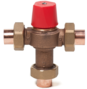
Mixing valves are used throughout building water distribution systems. The BCPC Article 2.2.10.7., Water Temperature Control, addresses several applications:
- Except as provided in Sentence (2), valves supplying fixed-location shower heads shall be individual pressure-balanced or thermostatic-mixing valves conforming to ASME A112.18.1/CSA B125.1, “Plumbing Supply Fittings.”
- Individual pressure-balanced or thermostatic-mixing valves shall not be required for shower heads having a single tempered water supply that is controlled by an automatic compensating valve conforming to CSA B125.3, “Plumbing Fittings.”
- Mixing valves that supply shower heads shall be of the pressure-balanced, thermostatic, or combination pressure-balanced/thermostatic type capable of maintaining a water outlet temperature that does not exceed 49°C, and limiting thermal shock.
- The temperature of water discharging into a bathtub shall not exceed 49°C.
Temperature-sensitive aerators, showerheads, etc., are all aftermarket products that offer an excellent safety function for those systems that are not otherwise protected. However, these devices are not alternatives to the Code-required pressure balance or thermostatic mixing valves.
Thermal expansion protection
When water is heated, its volume increases. This expansion often occurs when there is no simultaneous demand at the fixtures within the building. If a ‘nonreturn device (such as a backflow preventer, pressure reducing valve or check valve) is present in the cold water piping, the pressure in the building’s water distribution system can rise rapidly as the water is heated.
Although temperature and pressure (T&P) relief valves are installed on storage-type service water heaters to open if excessively high pressure occurs, it is not desirable for such valves to be constantly activated. Allowing water heaters to operate at excessively high pressures can create bursts of water and piping noise when a hot water fixture is first opened. It can also lead to leaks in fittings or valves, such as the T&P relief valve. The life expectancy of glass-lined water heaters can also be reduced by high pressure that causes flexing of the tank walls.
The BC Plumbing Code addresses the need for thermal expansion protection in the Notes to Part 2, A-2.6.1.11.(1). This Note states that to accommodate the increase in pressure caused by thermal expansion within a closed water distribution system, one of the following should be installed:
- a suitably sized diaphragm expansion tank designed for use within a potable water system,
- an auxiliary thermal expansion relief valve (T.E.R. valve) conforming to CSA B125.3, “Plumbing Fittings,” set at a pressure of 550 kPa or less and designed for repeated use, or
- other means acceptable to the authority having jurisdiction.
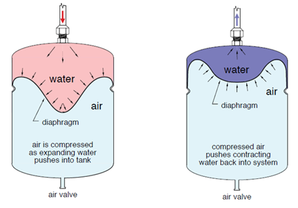
Although there are options to relieve excess pressure from thermal expansion, such as ball valves and ball cocks with built-in T.E.R valves, installing a suitably sized potable water expansion tank is the preferred method of accommodating thermal expansion in the water distribution system. The thermal expansion tank should always be placed in the cold water piping supplying the water heater, and always downstream of any non-return valve or device. This placement ensures that the tank will always have direct access to the pressure in the service water heater.
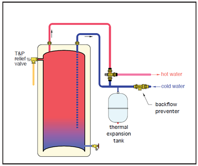
Thermal expansion tanks for domestic water heating systems are similar to expansion tanks used in closed hydronic systems. They have a steel shell and flexible butyl diaphragm. The diaphragm separates a sealed chamber of air in the lower portion of the tank from the water contained in the upper portion of the tank. Thermal expansion tanks for domestic water systems also include a non-corrosive polypropylene liner that separates the steel shell from potable water in the upper portion of the tank.
As water expands, the increased volume is forced into the tank, compressing the air under the flexible diaphragm, as illustrated in the figure below. In a system with a properly sized tank, the increase in air pressure is such that the T&P relief valve does not open during each normal heating cycle.
During installation, the air side of the thermal expansion tank must always be pressurized to match the line water pressure at the water heater. This ensures that the diaphragm in the tank is fully expanded against the tank’s shell before the water in the system expands. If the tank is underpressurized, a portion of its water side volume will fill with water before the water starts to expand. This needlessly wastes tank volume and reduces the tank’s ability to moderate pressure fluctuations. The air pressure within the tank is adjusted by adding or removing air through the Schrader valve on the tank.
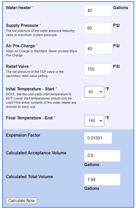
The minimum size of a potable water thermal expansion tank for a domestic potable water heating system can be determined using the equation below.
[latex]{V}_{min}={V}_{s}\times \left[\dfrac{{P}_{max}+14.7}{{P}_{max}-{P}_{L}}\right] \times \left[\dfrac{{D}_{c}}{{D}_{H}}-1 \right][/latex]
Where:
- Vmin = minimum total volume (not acceptance volume) of thermal expansion tank (US gallons)
- Vs = total volume of heated water in system (US gallons)
- Pmax = maximum allowed pressure in water heater, usually the T&P rating (psi)
- PL = pressure in cold water line supplying water heater (psi)
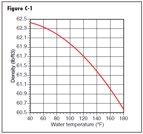
- DC = density of cold water based on the figure below (lb/ft3)
- DH = density of water at setpoint temperature based on the figure below (lb/ft3)
The graph below shows the relationship between water density and the water temperature for use in the potable water expansion tank sizing equation.
Example of sizing a potable water expansion tank
A plumber has decided to install an expansion tank on a system that contains 5 US gallons of water in the piping, and is using a 40 US gallon storage-type water service heater. The water enters the system at 40°F, but will be heated to 140°F. The T&P relief valve setpoint is 210°F. The water pressure has been reduced to 60 psi and the T&P relief valve setpoint is 150 psi. Determine the minimum size of thermal expansion tank required for the system.
Solution:
Enter all the information into the equation:
[latex]{V}_{min}=45\text{US gallons}\times \left[\dfrac{150\text{ psi}+14.7}{150\text{ psi}-60\text{ psi}}\right] \times \left[\dfrac{62.43\text{{ lb/ft}}^{3}}{61.38\text{{ lb/ft}}^{3}}-1 \right][/latex]
Solve the equation:
[latex]{V}_{min}=1.4 \text{ US gallons}[/latex]
Most manufacturers have online sizing tools available to ensure the plumber selects a potable water expansion tank that will meet or exceed the potable water distribution system needs.
Pressure tanks
Pressure tanks are virtually the same as potable water expansion tanks. The most significant difference between the two tanks is their functionality. An expansion tank handles potable water expansion and provides protection for water valves and heaters. A pressure tank lengthens the lifespan of a well pump. Pressure tanks, used on domestic water well systems, [JG1] are covered in the plumber level 4 content.
Hot water recirculation
The BC Plumbing Code Sentence 2.6.1.1.(2) requires that when there is a hot water distribution system of a developed length of more than 30m or supplying more than four storeys, the water temperature shall be maintained by recirculation or a self-regulating heat tracing system.
Although a self-regulating heat tracing system is an option, most installations will include a domestic hot water recirculation system (DHWR). Hot water recirculation systems work by circulating the water in the hot water distribution system back to the service water heater. This is done to ensure hot water is almost instantly available at every fixture that requires it, minimizing the waste of water while the user waits for hot water from the service water heater. For example, if a faucet was opened on a fixture that was 100 feet (30m) away from a service water heater, it could take 25 seconds or more to get hot water. This is based on the faucet not having a restricting aerator, the hot water travelling in copper pipe at the maximum velocity of 4 feet/sec, and the entire hot water distribution pipe has cooled to ambient temperature. Although this seems like an extreme case, low-flow aerators and other restrictions can create much longer wait times. A long wait for hot water at a remote fixture is a common occurrence in residential and ICI buildings. While the user waits for hot water, the fixture is flowing water to the building DWV system, essentially wasting water.
The ASHRAE Handbooks and ASPE Data Books mentioned in the BC Plumbing Code Sentence 2.6.3.1.(2) are good resources for the design and sizing of the cold and hot water distribution systems as well as the DHWR system. Most DHWR systems use a dedicated return line to allow the flow of water back to the service water heater. This additional pipe connects at one end to the downstream end of the hot water distribution system and the other end returns to the service water heater. The water can flow back to the water service heater by gravity if the system is designed correctly, but most systems use a pump to circulate the water. On complex systems, there may be several recirculation systems using multiple circulators. There are some retrofit systems for residential applications that do not have a dedicated return line but, instead, use the cold water distribution system to return water back to the service water heater.
Recirculation systems can be added to any system, including tankless water heaters. Some tankless heaters now have a recirculation system built in to them.
A simplified residential hot water recirculation system using a circulator pump is shown below. The dedicated return line is connected on one end as close as practical to the fixture furthest away from the service water heater, and the other end would connect at the domestic cold water inlet to the service water heater. Note the check valve installed in the dedicated return line to ensure the domestic cold water cannot “short-circuit” to the hot water distribution system.
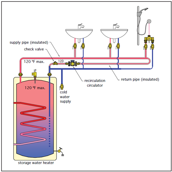
Controlling hot water recirculation system
Hot water recirculation systems can run continuously, but most installations will activate the circulator pump using one of these methods:
- an aquastat to turn the pump on and off based on the water temperature
- a timer to circulate water during low use periods
- a motion-sensor to activate the circulator only when fixture usage is about to happen
- manually-activated to circulate water during low use periods.
Some manufacturers have integrated a timer and an aquastat in with the circulator pump. This method of installation will ensure maximum energy savings when both controlling limits – fluid temperature observed by the aquastat and the timer setting – are satisfied.
Hot water circulator pump selection
Since a domestic hot water recirculation system using a dedicated return line is essentially a closed-loop heating system, many of the same selection principles can be used when selecting a circulator pump for a hydronic heating system. Ideally, the circulator pump needs to keep the recirculated water at the design temperature using the smallest model available. If the circulator pump is undersized, the water will cool before being delivered to the fixture; if oversized, the velocity of the water could erode the pipe material.
Circulator pump selection is a complex undertaking, as the designer must account for the type of piping material, minimum and maximum water velocity based on water temperature, temperature difference between hot water and the surrounding air, head[JG1] losses of the piping and fittings, minimum and maximum flow rates to ensure hot water at the furthest fixture, etc. Ultimately, pumps are sized with two critical pieces of information: how much fluid you want to move (flow) in gallons per minute , and how much pressure you need to overcome, typically measured in feet of head.
Just as in hydronic design, there are many ways to design a system. Some designs are simple enough to use just one circulator, while other designs may need multiple circulators, or one circulator with balancing valves. Circulator pump manufacturers are good resources DHWR system design information. Most circulator manufacturers provide a DHWR pump sizing method, or online sizing tool, to help designers select the correct pump. The sizing method will use different graphs, charts, and formulas to help select the best circulator pump for the application.
The following example will go through a basic DHWR circulator pump selection process for a residential application. This example will use copper tubing as the piping material. The domestic hot water temperature will be 140°F and there will be no point-of-distribution mixing valve used at the water heater. If a point-of-distribution mixing valve is used, the designer will need to account for the extra head loss as well as the lower hot water temperature.
Step 1: Decide if the copper hot water distribution piping will be insulated.
The tables below show the advantage of insulating the water lines. For example, an uninsulated 3/4 inch copper tube at 70°F ∆T (∆T is temperature differential between the hot water and the surrounding air) is 30 Btu/hr/ft of heat loss. An insulated ¾ inch copper tube at 70°F ∆T is approximately 10 Btu/hr/ft of heat loss. Lower heat loss will mean a smaller circulator pump can be selected.
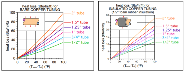
Note that the BC Building Code Sentence 9.36.4.4.(2) requires that all piping forming part of a continuously operating recirculating service water heating system shall be covered with piping insulation that is at least 12 mm thick.
For this example, insulated copper tube will be used.
Step 2: Estimate of length of pipe from service water heater to furthest fixture.
The dedicated return portion of the recirculation piping need not be considered, as that heat loss occurs after the last fixture and will not impact the supply water temperature.
For this example, a length of 50 feet from the service water heater to the furthest fixture will be used.
Step 3: Calculate the heat loss of the 50 feet of tubing based on an estimated pipe size.
This is done once the pipe sizing has been completed. Since pipe sizing will be done in the next Learning Task, this example will use ¾ inch copper tubing as the pipe size for all of the hot water distribution system, although it is likely that some downstream sections would be ½ inch copper tube.
Therefore, 50 feet of ¾ inch copper tube with a heat loss of 10 Btu/hr/ft will equal a total of 500 Btus of heat loss per hour.
Step 4: Calculate the recirculation flow rate required to maintain hot water temperature at the most remote fixture.
This is done using the universal hydronic formula shown below.
[latex]{f}_{r}=\dfrac{Q}{500 \times \text{delta-T}}[/latex]
Where:
- fr = the required recirculation flow rate (USgpm)
- Q = total heat loss of the DHW supply piping (Btu/hr)
- delta-T = the design temperature drop (degrees F)
The formula requires an allowable temperature drop (delta-T). The temperature drop from the heating source to the most remote fixture that is commonly used is 10°F, the same as for residential hydronic heating systems. The constant 500 used in the formula is derived from the weight of a US gallon of water at 60°F multiplied by 60 minutes (8.33 x 60 = 500), and is used only when water is the fluid in the system.
Complete the calculation: Flow rate = 500 Btu/hr ÷ (500 x 10OF)
After completing the calculation, the required recirculation flow rate for this example is 0.1 USGPM.
Step 5: Estimate the head loss of the recirculation loop.
The pressure driving the water along the pipes is the head. [JG1] This pressure is opposed by the friction losses in the pipes, which can be thought of as the pressure-difference-per-foot needed to push the water along at the required flow rate. This can be done using a formula such as the Darcy-Weisbach equation or the Hazen-Williams equation, or can be estimated using a graph or chart. Many pipe manufacturers have online capacity and friction loss calculators. The calculation will need to consider the type of material, the velocity of the water, and the required flow.
The figure below shows a portion of a larger graph that could be used for selecting pipe sizes that do not exceed the maximum permitted velocity, as well as estimating friction loss. Graphs are usually specific to one material but can include several wall thickness choices.
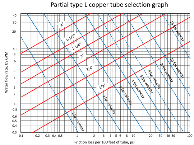
Tables are also commonly developed as an alternative to using graphs. The graph above includes information on several pipe sizes of the same material, but the table below was developed using the Hazen-Williams formula just for type L copper tubing friction loss. Other tables would need to be developed for different types of copper, or different materials.
| Flow rate GMP | ½″ | ¾″ | 1″ | 1¼″ | 1½″ | 2″ |
|---|---|---|---|---|---|---|
| 0.1 | 0.028 | 0.005 | 0.001 | 0.001 | 0 | 0 |
| 0.2 | 0.094 | 0.017 | 0.005 | 0.002 | 0.001 | 0 |
| 0.3 | 0.191 | 0.035 | 0.010 | 0.004 | 0.002 | 0 |
| 0.4 | 0.315 | 0.059 | 0.017 | 0.006 | 0.003 | 0 |
| 0.5 | 0.466 | 0.087 | 0.025 | 0.010 | 0.004 | 0.001 |
| 1 | 1.568 | 0.291 | 0.083 | 0.032 | 0.014 | 0.004 |
| 2 | 5.273 | 0.979 | 0.281 | 0.108 | 0.048 | 0.013 |
| 3 | 10.720 | 1.991 | 0.571 | 0.219 | 0.099 | 0.027 |
| 4 | 17.735 | 3.295 | 0.944 | 0.362 | 0.163 | 0.044 |
| 5 | 26.207 | 4.868 | 1.396 | 0.525 | 0.241 | 0.065 |
| 10 | 88.149 | 16.375 | 4.694 | 1.799 | 0.811 | 0.220 |
Using the Type L copper tubing friction loss table above, the head loss due to friction per 100 feet of ¾ inch type L copper tube at the flow of 0.1 US GPM (from Step 4) would be 0.005 feet. Since this DHWR example has 100 feet of pipe, the head loss from the table can be used as-is. If the DHWR piping circuit was shorter or longer a calculation would be made to determine the proportional head loss.
The static head (or height of the system) does not need to be accommodated in the total head loss calculation, but friction loss of fittings does need to be addressed. Fitting friction loss can be calculated using the actual resistance of fittings and valves, expressed in equivalent length of straight pipe, using the manufacturer’s literature. Alternatively, many designers use a rule-of-thumb method for fitting friction loss based on the type of material. The designer would typically add between 10% and 50% to the estimated friction loss for the piping.
In this example, a 50% fitting friction allowance will be added to the piping friction loss: 0.005 feet + 50% = 0.0075 feet of head of total equivalent friction loss.
Step 6: Selecting the circulator pump.
This pump selection example has a pumping requirement of 0.1 USGPM at 0.0075 feet. This is a very small pumping requirement that can be handled by a small circulator designed specifically for recirculation systems. The circulator can be selected using a pump performance curve. Most pump manufacturers provide a pump curve for every pump they make. Simply stated, a pump curve is a normally curved line drawn over a grid of vertical and horizontal lines to form a graph. The curved line represents the performance of a specific pump, while the gridlines provide units by which performance can be measured.
The figure below shows an example of a performance curve for a small pump that could be used as a circulator on the DHWR system for this example. The graph has two curves, showing the same model but with two different connection methods.
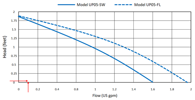
Using the flow rate of 0.1 USGPM and a total equivalent friction loss of 0.0075 feet of head, the calculated “duty point” of the circulator for this system can be determined. The duty point is where the flow rate and the head loss for the example intersect on the pump curve, shown by the arrows in the lower left of the graph. Since the duty point is under the pump curve, this pump could work for the example , but may be oversized.
Confirm water velocity
With so little friction loss to overcome, this pump is capable of easily meeting the flow rate required. Extending the arrow from the Head (feet) axis over to the pump curve for the UP05-SW model shows that the pump would be able to flow the maximum of approximately 1.6 GPM. With this amount of flow the maximum velocity for the piping material may be exceeded.
The velocity can be determined using the formula below:
[latex]V=\dfrac{Q}{A}[/latex]
Where:
- V = Water velocity inside the pipe (feet per second)
- Q = Flow rate of water inside the pipe (cubic feet per second)
- A = Area of pipe inside diameter (square feet)
This formula works great when flow rate is measured in the cubic form of a standard length unit. But when flow rate is measured in gallons per minute an alternate version of the formula can be used.
Using the formula below, the velocity created by the pump must be confirmed to be under the maximum recommendation of 3 feet per second for the smallest pipe in the system.
[latex]V=\dfrac{(0.408)Q}{D^2}[/latex]
Where:
- V = Water velocity inside the pipe (feet per second)
- Q = Flow rate of water inside the pipe (US GPM)
- D = Pipe inside diameter (inches)
For this example, the velocity in the 3/4 inch copper has been calculated to be 1.16 feet per second. This velocity is below the recommended 3 feet per second, so the circulator could be selected.
Conclusion
The circulator pump model has been determined for this example. The circulator pump body material must be approved for potable water applications. Brass, bronze, stainless steel, and some plastics can be used, but cast iron pump bodies are only used on non-potable systems like hydronic heating systems. Although the pump selected for this example was a single speed model, multi-speed and variable speed options are also available.
Pump sizing challenges
Sizing any pump is challenging. Pump selection is a function of pipework layout, affected by lengths of straight pipe and fittings. During the design phase of a project, the actual pipe route is unknown. When the system is actually installed the original estimated total equivalent friction loss may be inaccurate. This uncertainty can lead to an under-sized or over-sized circulator pump.
When a pump is undersized the system doesn’t get the required flow and doesn’t perform as designed. This can show up as long delays in waiting for hot water at faucets. Over-sizing, however, may not cause problems for several years. High velocity can cause noise but more importantly, copper pipes will develop pinhole leaks, most often at elbows and fittings. The pinhole leaks and wear on the inside diameter of copper piping is from turbulence and erosion-corrosion caused by the high velocity and can be complex and costly to repair.
One solution is to install variable speed pumps. Although not usually installed for domestic hot water recirculation due to their higher price tag, they would be able to run at just the right speed to provide the head and flow needed.
DHWR systems in ICI buildings
The figure below shows an example of a more complex DHWR design, employing one circulator pump but using balancing valves. It is imperative that these system designs are balanced to ensure that the water is recirculated equally from every riser. Several pump manufacturers offer online sizing tools to help design the DHWR recirculation system for ICI buildings.
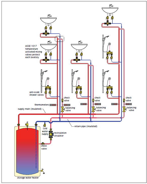
Now complete Self-Test 1 and check your answers.
Self-Test 1
Self-Test 1
- To protect a water meter from frost damage, where is the weak point located?
- Top
- Inlet
- Outlet
- Bottom
- Which shut off valve is located on the water service, immediately inside the building?
- Curb cock
- Service valve
- Main stop and drain
- Corporation cock
- Which water meter type is commonly used to measure and record small water flows?
- Turbine Meter
- Compound Meter
- Rotating disk meter
- Micro Compound Meter
- When in use, what will happen to an anode rod that is located in a hot water storage heater?
- Increase in size when in use
- Stays the same size in use
- Decreases in size when in use
- Change electrical charge several times
- What is the purpose of a service loop on a water service line?
- To increase the depth of the water service
- To decrease the depth of the water service
- To provide adequate room to mount the water meter
- To allow for settlement or movement of the water main
- When does the Code require that a check valve be installed on a water service pipe?
- When the water service is subject to backflow
- Check valves are never required on a water service
- Any time the water service is more than 3 ft below grade
- When the water service pipe is rated for cold-water only
- “A water pipe that passes through one or more storeys” is definition of:
- Main
- Riser
- Trunk
- Branch
- Shower valves must be pressure balanced, thermostatic-mixing, or controlled by a master thermostatic-mixing valve.
- True
- False
- What is a direct fired hot water heater?
- The heating source is located at the hot water storage tank
- A heat exchanger is inserted in the hot water storage tank
- A remote heating source heats the hot water storage tank
- A converter is inserted in the hot water storage tank
- Where should the downstream end of the domestic hot water recirculation line be connected?
- At the nearest cold faucet to the storage tank
- At the branch line leading to the closest hot water fixture
- Near the hot water outlet at the top of the storage tank
- To the cold water inlet to the storage tank, or to the bottom inlet of the tank
- To ensure equal flow in all circuits of a re-circulation system, what devices are installed?
- Check valves
- Balancing valves
- Booster pumps
- Flow inducing valves
- Circulation pumps on potable water systems must be what type?
- Bronze body
- Cast iron body
- Aluminum body
- Galvanized body
- What is the recommended minimum required water temperature for domestic hot water storage?
- 50 °C
- 60 °C
- 70 °C
- 80 °C
- According to the NPC, systems for solar heating of potable water shall be installed in conformance with which standard?
- CSA F378
- CSA F379
- CSA F383
- CSA F390
Check your answers using the Self-Test Answer Keys in Appendix 1.
Media Attributions
- Figure 1 Simplified residential water supply system by John Gordon is licensed under a CC BY-NC-SA licence.
- Figure 2 Typical small-diameter outside meter installation by Camosun College is licensed under a CC BY 4.0 licence.
- Figure 3 A water meter installed in a meter pit by Camosun College is licensed under a CC BY 4.0 licence.
- Figure 4 Possible components used for an inside small-diameter water meter installation by Camosun College is licensed under a CC BY 4.0 licence.
- Figure 5 A drawing with two water meters installed on an industrial system by Camosun College is licensed under a CC BY 4.0 licence.
- Figure 6 Small-diameter water meter face by Camosun College is licensed under a CC BY 4.0 licence.
- Figure 7 Internal parts of a nutating disc on the left and a piston water meter on the right by Camosun College is licensed under a CC BY 4.0 licence.
- Figure 8 A small-diameter residential meter installed inside the building using a meter yoke by Camosun College is licensed under a CC BY 4.0 licence.
- Figure 9 A simple branch system layout for a cold water residential installation by Camosun College is licensed under a CC BY 4.0 licence.
- Figure 10 A simple home-run manifold system layout for a cold water residential installation by Camosun College is licensed under a CC BY 4.0 licence.
- Figure 11 A simple combination system layout for a cold water residential installation by Camosun College is licensed under a CC BY 4.0 licence.
- Figure 12 Simplified downfeed and upfeed examples by Camosun College is licensed under a CC BY 4.0 licence.
- Figure 13 One variation of the upfeed booster system design using 2 separate pumps by Camosun College is licensed under a CC BY 4.0 licence.
- Figure 14 Plan view of the recommended connection method for a standalone residential fire sprinkler system by Camosun College is licensed under a CC BY 4.0 licence.
- Figure 15 A frost-proof hydrant on the left and a standard hose bibb on the lower right by Caleffi Hydronic Solutions, used with permission.
- Figure 16 One example of indirect domestic water heating by Caleffi Hydronic Solutions, used with permission.
- Figure 17 A simplified illustration of the internal components in a gas-fired tankless water heater by Caleffi Hydronic Solutions, used with permission.
- Figure 18 The typical components used with a tank-type electric water heater by Caleffi Hydronic Solutions, used with permission.
- Figure 19 A new and an old anode rod by Camosun College is licensed under a CC BY 4.0 licence.
- Figure 20 Electric water heater element cycling by Camosun College is licensed under a CC BY 4.0 licence.
- Figure 21 The typical components used with a tank-type gas-fired water heater by Caleffi Hydronic Solutions, used with permission.
- Figure 22 Point-of-use water heater with filter by Camosun College is licensed under a CC BY 4.0 licence.
- Figure 23 Typical solar water heating system using a storage tank with an internal heat exchanger by Caleffi Hydronic Solutions, used with permission.
- Figure 24 Legionella growth chart by Camosun College is licensed under a CC BY 4.0 licence.
- Figure 25 Pump curve example for an office building John Gordon is licensed under a CC BY-NC-SA licence.
- Figure 26 2 tank-type heaters piped in series by Camosun College is licensed under a CC BY 4.0 licence.
- Figure 27 2 tank-type heaters piped in parallel by Camosun College is licensed under a CC BY 4.0 licence.
- Figure 28 On-demand water heaters using cascading controls for an ICI application by Camosun College is licensed under a CC BY 4.0 licence.
- Figure 29 A mixing valve installed to temper the entire hot water distribution system by Caleffi Hydronic Solutions, used with permission.
- Figure 30 Pressure-balanced tub and shower valve by Camosun College is licensed under a CC BY 4.0 licence.
- Figure 31 An example of a temperature activated mixing valve by Camosun College is licensed under a CC BY 4.0 licence.
- Figure 32 The correct location of a potable water expansion tank by Caleffi Hydronic Solutions, used with permission.
- Figure 33 Potable water expansion tank cycling by Caleffi Hydronic Solutions, used with permission.
- Figure 34 Water density and the water temperature graph by Caleffi Hydronic Solutions, used with permission.
- Figure 35 Example of an online tool worksheet for the previous example by Caleffi Hydronic Solutions, used with permission.
- Figure 36 Example of an online tool worksheet for the previous example by Camosun College is licensed under a CC BY 4.0 licence.
- Figure 37 Simplified water recirculation system for a residential distribution system by Caleffi Hydronic Solutions, used with permission.
- Figure 38 Compare bare copper tube to insulated copper tube heat loss by Caleffi Hydronic Solutions, used with permission.
- Figure 39 Graph used for selecting type L copper tube by Camosun College is licensed under a CC BY 4.0 licence.
- Figure 40 Example of a circulator pump performance curve by Camosun College is licensed under a CC BY 4.0 licence.
- Figure 41 DHWR system using balancing valves by Caleffi Hydronic Solutions, used with permission.
