Learning Task 3
Describe the Installation of Piping for Municipal Water Systems
This section will look at the installation of the piping upstream of the curb stop. Although plumbers may not be directly involved with the installation of the municipal water supply piping, the materials and techniques used are the same for the installation of both residential and ICI water service pipes, which plumbers would install.
Pipe and Fitting Materials
As discussed earlier in this Competency, municipal water systems are designed by engineers, or by qualified designers, using current engineering practices. Since the municipal system is outside the scope of the BC Plumbing Code, the designers have more freedom to choose materials and fittings for the water supply system upstream of the water service pipe. The municipal water distribution system will include pipes of a variety of sizes and materials and designers must have flexibility to choose these components based on recognized standards and past experience. However, the majority of municipal water distribution systems will use pipes and fittings that meet the requirements of the BC Plumbing Code Tables A-2.2.5., 2.2.6. and 2.2.7. These Tables are a summary of pipe and fitting applications so are used by plumbers when making choices for the design of the building water distribution system and the water service pipe.
The Tables reference the types of piping and fittings in one column and have separate columns for above-ground potable water system and underground potable water systems. The above-ground column is separated into two more columns, one for cold water and one for hot water. The underground column is also separated into two more columns, one for under the building, and the other for outside the building.
The list below shows a selection of piping and fittings from the BC Plumbing Code (BCPC) Tables A-2.2.5., 2.2.6. and 2.2.7 that could be used for underground municipal distribution systems and the water service pipe to buildings.
- Polyethylene water pipe and tubing, Series 160 sizes with compression fittings. BCPC Article 2.2.5.4 applies. Note: Permitted only for water service pipe.
- Polyvinyl chloride (PVC) pressure fittings. BCPC Article 2.2.5.7 applies.
- Polyvinyl chloride (PVC) water pipe. BCPC Article 2.2.5.7 applies. Note: Not permitted in hot water systems.
- Dimension ratios (DR) or standard dimension ratios (SDR) 14, 17, 18, 21, 25 and 26.
- Schedule 40 in sizes from ½ inch to 2½ inches inclusively
- Schedule 80 in sizes from ½ inch to 6 inches inclusively
- PVC fittings, Schedule 80. BCPC Sentence 2.2.5.7.(2) applies.
- Crosslinked polyethylene (PEX) pressure tubing. BCPC Article 2.2.5.6 applies.
- A-2.2.5.6.(1) Crosslinked Polyethylene Pipe and Fittings. There are some special installation requirements for the use of crosslinked polyethylene pipe and its associated fittings. Reference should, therefore, be made to the installation information in CAN/CSA-B137.5, “Crosslinked Polyethylene (PEX) Tubing Systems for Pressure Applications.”
- Chlorinated polyvinyl chloride (CPVC) water pipe. BCPC Article 2.2.5.8 applies. Note: Not to exceed design temperature and design pressure stated in Sentence 2.2.5.8.(2).
- Polyethylene/Aluminum/Polyethylene (PE/AL/PE) pressure pipe. BCPC Article 2.2.5.12 applies.
- Crosslinked Polyethylene/Aluminum/Crosslinked Polyethylene (PEX/AL/PEX) pressure pipe. BCPC Article 2.2.5.13 applies.
- Polypropylene (PP-R) pressure pipe. BCPC Article 2.2.5.14 applies.
- Cast-iron water pipe (Ductile iron). BCPC Article 2.2.6.5 applies.
- Cast-iron screwed fittings. BCPC Articles 2.2.6.6 and 2.2.6.7 apply.
- Stainless steel pipe. BCPC Article 2.2.6.11 applies.
- Stainless steel tube. BCPC Article 2.2.6.15 applies.
- Welded and seamless steel galvanized pipe. BCPC Article 2.2.6.8 applies. Note: Permitted only in buildings of industrial occupancy as described in Book I (General) of this Code, or for the repair of existing galvanized steel piping systems.
- Copper and brass pipe. BCPC Article 2.2.7.1 applies.
- Brass or bronze threaded water fittings. BCPC Article 2.2.7.3 applies.
- Copper tube Types K and L soft temper. BCPC Article 2.2.7.4 applies.
- Solder-joint water fittings. BCPC Article 2.2.7.6 applies.
The BC Plumbing Code Tables A-2.2.5., 2.2.6. and 2.2.7 include a column that references the applicable standard for each type of pipe and fitting. The BCPC Article that is referenced also directs the plumber to the applicable standard. One standard that is not mentioned in the Code, but is followed by manufacturers of piping used on potable water systems, is the ANSI/NSF Standard 61: Drinking Water System Components – Health Effects. NSF International is an independent, not-for-profit, non-governmental organization that is dedicated to improving global health through the development of standards and certifications that protect food, water, products and the environment.
Common Pipe Materials for Underground Systems
The water supply system includes piping and fittings in several different sections of the system. The water purveyor makes decisions on piping and fittings for transmission lines, in-plant systems, the distribution system (mains), and service lines. Common piping materials used by the municipal water supply system designer are ductile iron, PVC, HDPE, concrete pressure pipe, PEX, copper tubing, and polyethylene tubing. Some of the considerations made by municipal water supply system designs for selecting pipe material and fittings are listed here:
- Meets ANSI/AWWA/CSA standards
- Meets NSF 61 standard
- Strength: internal pressure as well as external loads (backfill, traffic)
- Pressure rating
- Durability: water tight for service life
- Corrosion resistance: soil conditions, water pH, and chemistry
- Inner surface smoothness: C value, roughness causes head loss
- Ease of tapping and repair
- Installation labour cost
The plumber must decide on the piping and fittings for the water service pipe. Common piping materials used by plumbers for large diameter water service pipes (approximately 4 inch and greater) are ductile iron and PVC. Small diameter water service piping, such as copper, PEX, and polyethylene, are covered in Competency B-2 below.
Four of the most common materials used for municipal water distribution systems are covered below.
Ductile-iron
Ductile iron pipe is a type of cast iron pipe used for potable water distribution. Ductile cast iron is produced by a technique known as centrifugal casting. The molten ductile iron is poured into a rapidly spinning water-cooled mold. Centrifugal force causes the molten iron to spread evenly around the circumference of the mold.
This type of pipe, when used for potable water pipe, must be cement mortar lined on the interior wall to reduce the process of tuberculation (electrochemical corrosion) inside the pipe network. The cement mortar lining provides an area of high pH near the pipe wall and provides a barrier between the water and the pipe, reducing its susceptibility to corrosion. Over time, tuberculation can result in restricted flow because it decreases the inside diameter, thus the cross-sectional areas of the pipe. The cement lining forms a physical barrier between the pipe wall and the minerals found in the water. This barrier does not allow the minerals to adhere to the pipe wall. The exterior of the pipe is coated with bituminous coating. The primary purpose of the coating is to minimize atmospheric oxidation for aesthetic reasons but not act as a form of corrosion control.
Joining of ductile-iron piping and fittings is typically done with push-on or mechanical joints, but can utilize flanged connections for valves and fittings. Common sizes are 3 to 64 inch (75 to 1625 mm)
Polyvinyl chloride (PVC)
PVC is the most widely used material for underground municipal water distribution systems. PVC pressure pipe is known as a low-cost solution with strength, versatility, durability, and an easy installation process to back its popularity. PVC is made of polyvinyl chloride, a widely used thermoplastic material that can be molded into different shapes. Note that all underground PVC pipe installations need to include tracer wire laid alongside, and at the bottom, of a new water main pipe.
There are no governing bodies that require specific color coding and, therefore, the PVC pipe industry has self-standardized color coding of PVC pipe. The typical industry color coding standard of PVC pipe is:
- Blue for pressurized potable water
- Green for sewer, both gravity and force main
- Purple for reclaimed (non-potable) water
- White for general use – (plumbing, Drain/Waste/Vent, or water well)
- Gray for general use – (typically plumbing and electrical)
Joining of PVC pressure piping and fittings is typically done with push-on or mechanical joints, with solvent cement joints generally used for smaller diameters (less than 4 inch). Common sizes used in the municipal water distribution system range from 2 inch to 60 inch (50 mm to 1525 mm)
High density polyethylene (HDPE)
High-density polyethylene, known as HDPE, is a denser version of polyethylene pipe and is a polyethylene thermoplastic made from petroleum. HDPE pipe can be joined by butt welding, electrofusion welding, socket welding, or extrusion welding. These types of connections are heated during the joining process, creating a completely homogenous joint so the weld becomes as strong, or stronger, than the existing pipe on either side of the weld. There is no need to use rubber seals or jointing chemicals, as is used for joining PVC pipe. Common sizes are 1¼ inch to 48 inch (32mm to 1200mm).
Concrete pressure pipe
Concrete pressure pipe (CPP) can be manufactured to meet any combination of working pressure, surge pressure, earth loads, and live loads. The cement mortar provides an alkaline environment that passivates the steel in most natural soils and water environments. The pipe has self-centering steel joint rings and rubber gaskets to ensure water tightness and joint flexibility for potential ground movements, and once installed needs no maintenance. Fittings can be designed and built to almost any shape or geometry. Water purveyors have traditionally used CPP for the transmission piping system that connects the reservoirs to downstream treatment facilities. Common sizes for this type of piping is 14 inch to 140 inch (350 mm to 3600 mm).
CPP is not to be confused with asbestos-cement pressure pipe (also referred to as transite pipe and white pipe), which was extensively used by plumbers prior to it being discontinued in North America in the late 1970s due to health concerns associated with the manufacturing process and the possible release of asbestos fibres from deteriorated pipes.
Pipe and Fitting Pressure Ratings
Water supply system piping materials must withstand higher than normal pressures caused by pump start-up, water hammer, etc. This increased pressure can be significantly above the design working pressure of the system. Water supply system designers will choose materials with pressure ratings that will withstand any anticipated pressure increase based on engineering documents and past experience. To accommodate the wide range of pressure in a water supply system, manufacturers make pipe and fittings with a variety of wall thicknesses for different pressure ratings. For example, small diameter PVC pipe is rated by schedule, but larger PVC pipe is typically rated using “dimension ratio” (DR) and “standard dimension ratio” (SDR). Ductile-iron is rated using a Pressure Class designation.
Plumbers were introduced to pipe and tubing standards in the level one content so the following is just a review.
Standard dimension ratio (SDR) explained
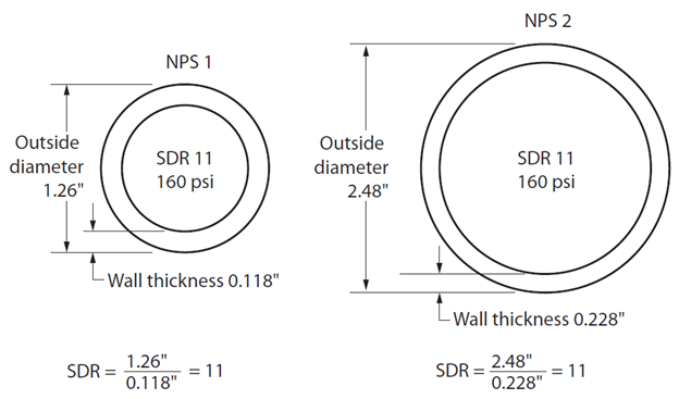
The terms “dimension ratio” and “standard dimension ratio” are widely used in the PVC pipe industry. Both terms refer to the same ratio, which is a dimensionless term that is obtained by dividing the average outside diameter of the pipe by the minimum pipe wall thickness. Originally SDR referred only to a particular series of numbers (51, 41, 32.5, 26, 21, etc.) while DR was used for any non-SDR numbers. It is now common to use the two terms interchangeably.
- SDR = outside diameter (OD) ÷ minimum wall thickness
Theoretically, different sizes of piping made of the same material, with the same SDR, should have the same pressure ratings. For example, 1 inch and 6 inch PVC pressure pipe with an SDR 26 rating are both suitable for 1.1 MPa (160 psi). The figure below shows a cross-sectional drawing of two different sizes of plastic pipe: NPS 1 and NPS 2. Each pipe is made of the same kind of plastic. Notice the increased wall thickness of the larger diameter pipe. When the outside diameter is divided by the wall thickness, the ratio or SDR is the same. Each pipe has an SDR of 11, which means that both sizes of pipe can be used at pressures up to 160 psi.
An example for a water supply system design specification could be DR18 for 100mm to 300mm PVC pipe, but DR25 for 350mm to 600mm PVC pipe.
Pressure class explained
Pressure classes are defined as the hydrostatic water working pressure of the pipe in psi. The pressure classes include a surge allowance of 100 psi with a safety factor of 2. The standard pressure classes are determined by the ANSI/AWWA C151/A21.51 standard for “Ductile-Iron Pipe, Centrifugally Cast”. The BC Plumbing Code Article 2.2.6.5., Cast-Iron Water Pipes, refers to several standards for ductile-iron pipe, fittings, and gaskets.
For example, a water supply system designer could decide that ductile-iron pipe must be supplied in minimum Pressure Class 350 for 4″ through 12″ (100 mm through 300mm); Pressure Class 250 for 14″ through 20″ (350mm through 500mm); Pressure Class 200 for 24″ (600mm), and Pressure Class 150 for 30″ (750mm) and larger.
Fitting Designs for Underground Systems
This section will discuss fittings specific to ductile iron and PVC piping used for underground water supply systems that have not been covered by previous content. Look back at the content “Describe Fittings Used in the Pipe Trades” from the plumber Level One textbook for a review of commonly used fittings in the pipe trades.
Ductile-iron and PVC piping for underground municipal water supply systems are traditionally installed in a trench and, for large city applications, could cover hundreds of square kilometers. The installation would require fittings for changes of direction and elevation, as well as the installation of valves, fire hydrants, pressure-reducing stations, and service connections.
To accommodate small changes in direction and elevation, this type of system would use fittings that have much smaller angles than fittings used by plumbers in other mechanical systems, such as drainage systems or building water distribution systems. Manufacturers of ductile-iron and PVC fittings make elbows with change-of-direction angles such as 5 degrees and 11¼ degrees to ensure the joint deflection does not exceed specifications.
Joint deflection can be used to make small changes of direction when a trench needs to divert the pipe from a straight line. Fittings for both ductile-iron and PVC are well suited to applications where joint deflection is required but the installer must not exceed the deflection limitation specified by the manufacturer. Most manufactures limit joint deflection to a maximum of 5 degrees. More content on joint deflection is included in the section “Installation techniques for ductile-iron and PVC piping and fittings” below.
While ductile-iron fittings are cast in static moulds, PVC fittings are manufactured using high-pressure injection molding techniques, or they are fabricated using PVC parts to create a new fitting. Molded fittings are made by injecting hot plastic into a pre-made mold. This technique is generally used for the most common fitting types and sizes as it lends itself to mass production. To create fabricated fittings, manufacturers may cut, weld, and bend PVC to construct a fitting that cannot be easily molded. This process is less automated than injection molding, so fabricated fittings tend to be more expensive than molded fittings. Some manufacturers choose to fabricate large diameter, or unique fittings, because it is more cost effective than creating a special mold for something that will rarely be used. Molded fittings are typically for diameters up to approximately 12 inch, and fabricated fittings are for diameters up to approximately 60-inch PVC fittings.
Plumbers need to be aware that PVC pipe and fittings can be used with ductile-iron systems. This means that PVC pipe and fittings are manufactured in iron pipe size (IPS) outside diameter, as well as cast iron outside diameter (CIOD) sizes. Manufacturers make adapters to ensure the pipe and fittings are compatible.
The list below shows common fitting designs for municipal water supply systems using ductile-iron and PVC pressure piping.
- Bends (standard or custom angles)
- Couplings
- Tees
- Reducers
- Adapters
- Plugs
- Tapped couplings
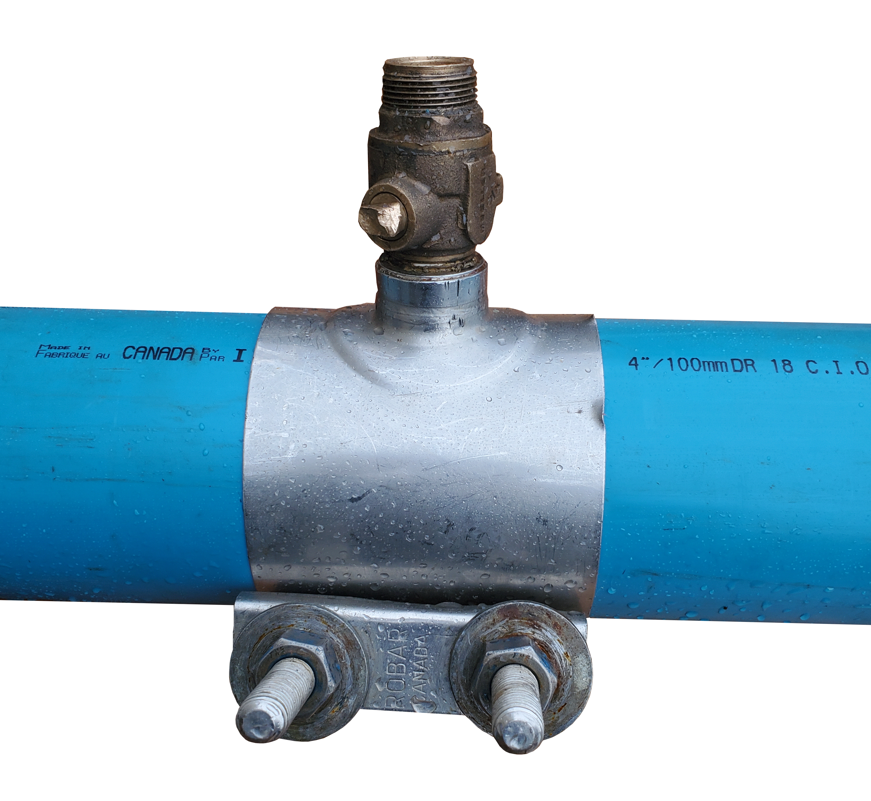
Another type of fitting that is used on underground municipal water supply systems is the service saddle. A service saddle is a threaded outlet that is attached to a larger diameter pipe, usually the water main, using straps, U-bolts, or brackets of various designs. Different materials, such as ductile-iron, brass, and stainless steel, are used based on the water purveyors’ specifications.
Whenever possible, water purveyors use tapped couplings, or tapped tees, to connect the water service pipe to the main. Under specific conditions water purveyors may allow for the water service pipe connection to be made by direct-tapping into the pipe wall. Most purveyors will specify the use of a service saddle to complete the water service pipe connection if a tapped coupling or tapped tee is not available.
Repair couplings are another fitting that are used on underground municipal water supply systems and larger diameter water service pipes. Most PVC manufacturers make a fitting that is designed to simplify and speed up the repair operation. The double bell design repair coupling is used as it can be slid all the way onto one spigot, and then slid back onto the other spigot. To complete a repair, a section of damaged pipe would be removed and a new piece of pipe, along with two repair couplings, would be used to re-assemble the system.
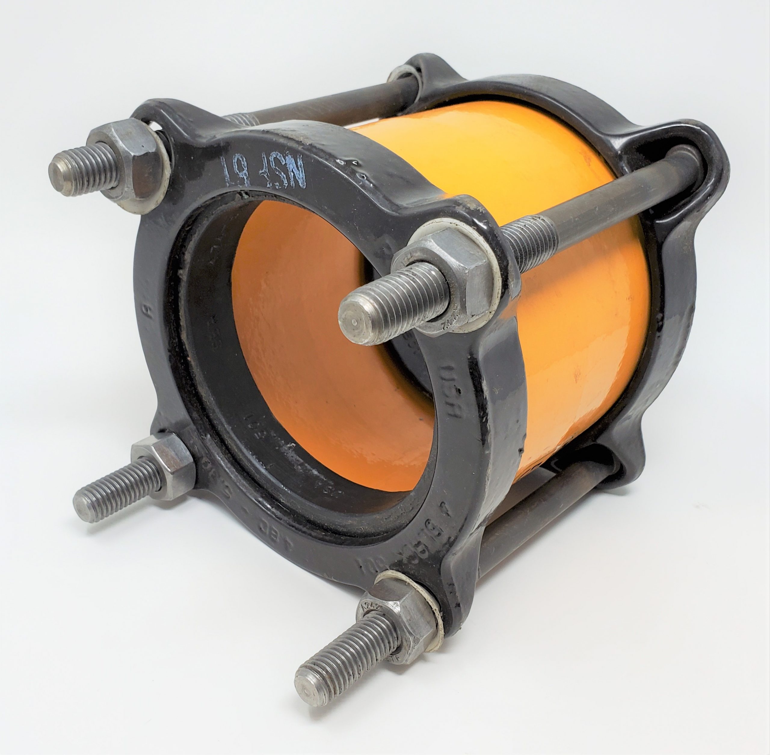
Alternatively, third party mechanical couplings can be used to complete a pipe repair. These types of couplings can also be used to join plain end piping, as well as to make a non-restrained connection between two pipes of the same nominal size but with same or different ODs.
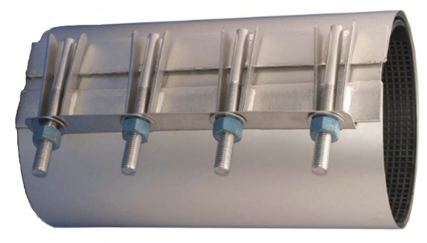
Repair clamps are also available and are used to effectively repair holes or breaks in water mains. The figure below shows a stainless steel repair clamp.
Resisting Thrust in Underground Systems
Typically, numerous fittings are needed to create the desired piping configuration. The fittings and pipe must remain in their installed position or leaks and blowouts will occur. Water that is in motion and under pressure can exert tremendous forces inside a piping system. Thrust is one of these forces that pushes against valves, fittings, and hydrants, causing fittings to leak or to come apart entirely. Water pressure and sudden changes in water velocity cause thrust.
It is impossible to eliminate thrust, but it is possible to control the effects of thrust. As the pipe changes direction or elevation, and as fittings are placed to accommodate distribution branches, the fittings and pipe must be protected from disconnection by some form of joint restraint. Since several types of pipe and fittings are used, there are several types of joint restraint methods used by municipal water supply system designers and plumbers.
Some of the common methods to resist thrust are listed here:
- Thrust blocks using correctly sized and placed concrete blocks for horizontal forces
- Thrust anchors using correctly sized and placed concrete blocks for vertical forces
- Traditional push-on joints using external clamps and rods
- Mechanical joints using integral external joint restraint
- Proprietary push-on joints using specially designed locking gaskets (internal restraint)
Restrained push-on and restrained mechanical joints are used for resisting thrust forces as an alternative to thrust blocking. Some special self-restrained joining systems are used for trenchless (horizontal directional drilling) applications that will not be covered by this content, but are popular for municipal water supply system designers when challenged with upgrading old systems, or installing new systems, in built-up areas of their municipalities.
External and internal restrained joints are covered in the content below under the heading “Special purpose joint designs”. The information that follows will cover only the installation of thrust blocks and thrust anchors.
Describe Thrust Blocks and Thrust Anchors
Thrust blocks and thrust anchors are one method used to aid in keeping underground pipe in its installed position. Three areas that require restraint are described below.
- At valves – All valves must be anchored. This includes valves installed in a chamber or in line with the pipe, whether it is operated frequently or only once a year.
- At changes in direction (vertical or horizontal) – Fittings such as elbows, tees, or dead ends must be restrained since they involve a significant directional change for the fluid.
- At reductions in size – The thrust component at reductions in size will depend on the amount of the reduction, and must be adequately restrained.
The thrust blocks and thrust anchors are poured concrete reinforcements placed at branches, fittings and changes of direction or elevation. Thrust blocks are used where primarily horizontal forces are created, and thrust anchors are used primarily where vertical forces need to be restrained.
Thrust blocks
Thrust blocks prevent separation of joints and pipe by transferring the horizontal thrust force in the piping system at a fitting to the undisturbed soil behind the thrust block. This means the area behind the thrust block must engage enough soil area to resist the resultant thrust force at a change in direction. Figure 38 shows a plan view of several typical thrust block locations in a municipal water supply system.
Thrust anchors
Thrust anchors (also referred to as gravity thrust blocks) are used to resist thrust at vertical down bends. A thrust anchor uses the weight of the concrete block to balance the vertical thrust force. Shackle rod, or strapping, is installed around the fitting and embedded in the concrete to help hold the assembly in place. The figure below shows elevation views of two typical thrust anchor installations.
A properly designed thrust block or thrust anchor involves much more than dumping a load of concrete in a trench. The design involves consideration of undisturbed soil, soil bearing strength, test pressure, pipe size, fitting configuration, and trench depth to determine the bearing area of the thrust block or thrust anchor.
Resisting thrust in very poor soils
Where the pipeline passes through soils having little or no bearing strength, thrust forces may be restrained by the encasement of the fitting in concrete and the extension of this pour to form a monolith having sufficient inertia to resist the thrusts. It may also be possible to loop tie rods around the fitting and anchor the tie rods into an upstream concrete pour across the trench in more stable soils. Mechanical thrust restraints may also be used in these cases.
Installing Thrust Blocks
When the water supply system design calls for the use of thrust blocks, concrete must be poured into a form built in the field by the installer. Concrete is poured between the fitting and undisturbed native soil at the side of the trench using forms, such as plywood sheets, to shape the block. When constructing thrust blocks, care needs to be taken to prevent the concrete from covering the joints at fittings, the weep holes in hydrants, and operating mechanisms of valves. The use of polyethylene film to cover the fitting will help if future disassembly, or revision, is desired.
While the design engineer usually specifies the concrete mix for thrust blocks, compressive strength at 28 days should be at least 2,000 psi and minimum curing time should be five days. When installing thrust blocks, the dimensions should be strictly adhered to as they have been designed for the specific water pressure and external soil conditions. Alternatively, pre-cast thrust blocks can be used if approved by the design engineer.
Sizing Thrust Blocks
The recommended bearing area to be established by the concrete pour may be given by the design engineer, or may be determined in the field by the installer. The area (ft.²) can be calculated by determining the total thrust generated at the fitting.
Here is an example problem to help work through the thrust block sizing method.
STEP # 1. Gather all the required information.
- Fitting details where thrust block is required (for example 6 inch 90 degree elbow)
- Working pressure of the system (for example 100 psi)
- Bearing load of soil. (for example, estimated soil type as sand and gravel cemented with clay. The bearing load for this type of soil is 4000 lbs per square foot (from the Table below).
These soil bearing capacities are approximate and conservative. For the most accurate design it is recommended that soil bearing tests be carried out by a competent soils engineer.
| Organic Material (such as Peat, etc.) | 0 lb/ft² |
|---|---|
| Soft Clay | 1000 lb/ft² |
| Sand | 2000 lb/ft² |
| Sand and Gravel | 3000 lb/ft² |
| Sand and Gravel Cemented with Clay | 4000 lb/ft² |
| Hard Pan | 5000 lb/ft² |
STEP # 2. Determine the thrust force at each fitting from the table below.
For example: The 6-inch 90-degree elbow that we are using will produce 54 lbs of thrust for every 1 psi of working pressure.
The total thrust force for this application will be 54 pounds of thrust per 1 psi x 100 psi of pressure = 5400 pounds of thrust.
| Pipe size | Dead-end or Tee | 90 degree elbow | 45 degree elbow | 22½ degree elbow | Side thrust per degree of deflection in pipe line joint |
|---|---|---|---|---|---|
| 3 | 12 | 17 | 9 | 5 | 0.24 |
| 4 | 19 | 26 | 14 | 8 | 0.35 |
| 6 | 38 | 54 | 29 | 15 | 0.72 |
| 8 | 66 | 93 | 50 | 26 | 1.22 |
| 10 | 107 | 151 | 82 | 42 | 1.97 |
| 12 | 153 | 216 | 117 | 60 | 2.78 |
| 14 | 207 | 293 | 159 | 81 | 3.77 |
| 16 | 268 | 397 | 205 | 105 | 4.86 |
| 18 | 344 | 485 | 264 | 134 | 6.65 |
| 20 | 426 | 600 | 326 | 165 | 7.90 |
| 24 | 615 | 867 | 472 | 239 | 11.50 |
| 30 | 963 | 1258 | 740 | 357 | 18.80 |
| 36 | 1390 | 1960 | 1166 | 540 | 26.60 |
STEP # 3. Determine the total bearing area required.
For this example, divide the total thrust force by the bearing strength of the soil.
Total thrust 5400 lbs ÷ Bearing load of soil 4000 lbs per square foot = 1.35 square feet of bearing required.
The concrete thrust block that is installed must bear up against the undisturbed soil for an area of at least 1.35 square feet.
Joining Methods for Ductile-Iron and PVC Piping and Fittings
There are a variety of ductile iron and PVC pipe joints on the market. Joining pipe together is just as important as the pipe itself. The different types of joint designs will allow the designer maximum flexibility when selecting piping and fittings for various applications, such as:
- joints that can restrain the pipe.
- joints with primary use for above-ground applications only.
- specialty joints that allow for deflection and expansion/contractions within the same coupling.
- joints that allow a span of greater distance than the pipe length.
- joints that use trenchless technology to install piping under roadways, rivers, etc.
For municipal water supply systems and large diameter building water service pipes (typically 4 inch and greater) requiring no specialty joints, both ductile-iron and PVC use similar methods to join piping and fittings. This section will cover the 2 most common methods used to join ductile-iron and PVC piping and fittings: push-on and mechanical joints.
The most common choice for pipe ends is the bell and spigot design. The bell end (hub end) receives the spigot (plain end) as shown in the cutaway figure below.
Push-on Joints
The push-on joint has been used since the 1950s and is the most common joint used for underground water supply systems. This joint consists of a single elastomeric gasket placed in a groove inside the bell end of the pipe. Elastomeric refers to a flexible synthetic rubber-like compound (neoprene) designed for specific uses. Some elastomeric compounds, for example, must be able to resist different chemicals, temperatures and pressures. This allows manufacturers to supply elastomeric gaskets for many different applications. For example, the standard gasket supplied may be a Styrene Butadiene (SBR) gasket, but other gasket materials such as EPDM, Nitrile, Neoprene and VITON® are also available. Nitrile gaskets are an example of a gasket option that is used for applications where fittings must be buried in soil with hydrocarbon contamination.
After lubricating the joint in accordance with the manufacturer’s instructions, the spigot end of the pipe is pushed past the gasket, compressing it and forming a seal that is tight versus high internal pressures. Assembly of the push-on joint is simple and fast, and it can be assembled under wet-trench conditions or even under water.
The basic push-on joint is a non-restraint joint, but special purpose designs are available for push-on joints that are considered restrained joints.
Different push-on joint designs are used by various manufacturers. This means the bell socket is different for each type of gasket and, consequently, the gaskets are not interchangeable. Care must be exercised to make certain that the correct gasket is being used for the joint design being installed and that the gasket faces the proper direction.
Mechanical Joints
The term mechanical joint fitting refers to a variety of fittings that use specially designed clamps and elastomeric gaskets to connect the piping and fittings.
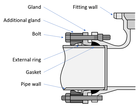
Mechanical joint connections are primarily used in fittings and valves. These joints use the gland’s compression against the bell to wedge the gasket, forming a watertight seal. The mechanical joint has four parts: a flange cast with the bell, a gasket that fits in the bell recess, a gland (follower ring) to compress the gasket, and tee-head bolts with nuts for tightening the joint. The basic mechanical joint is not a restrained joint and so offers no practical resistance against joint separation due to thrust forces. Common sizes for this design are from 4 inch through 24 inch, with special orders available up to 48 inch.
The figure below shows a ductile-iron mechanical joint fitting. Note that the mechanical joint fitting still uses a bell to accommodate a gasket, unlike the flanged fitting.
Flanged Joints
Flanged joints for municipal water supply systems are similar to flanged joints for other fluid applications. Flanged joints are seldom used for underground municipal water supply systems or building water service piping except for valves and fittings for large meter settings, valve vaults, and similar installations. This joint is most commonly used for above-ground piping in pump rooms, water treatment plants, and is occasionally used with valves adjacent to fire hydrants. Because of its rigidity, the flanged joint is not recommended where heavy settlement or vibration is likely to occur.
The figure below shows a ductile-iron flanged reducer. Note the absence of a bell to accommodate a gasket. Instead, a full-face flange gasket is used for this design.
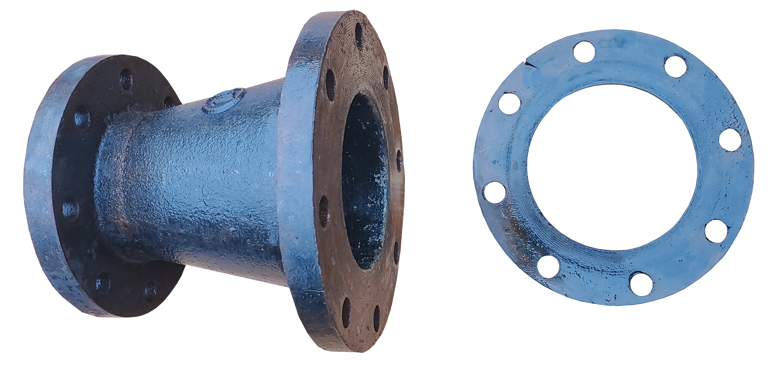
Although common on ductile-iron systems, PVC pipe may be connected to flanged joints by using a flange adapter. As is the case with ductile-iron, flanged joints on PVC systems are not recommended for buried underground installations.
Special-Purpose Joint Designs
There are many variations of the joining types based on the piping material and fitting requirements. Joints designed to restrain the pipe and fitting connection, either internally or externally, are available as an alternative to thrust blocks and thrust anchors. Several designs use a clamp on the wall of the pipe and tie back to a mating collar on the fitting or the pipe bell. The use of these devices may provide the entire thrust restraint necessary at the fitting, in sizes up to 60 inches (1500 mm). The use of several thrust restraints to tie together two or three lengths of pipe on either side of the fitting may be required.
The content below covers some of the popular special-purpose designs for ductile-iron and PVC piping and fittings.
Push-on joint restraint design
There are several variations of this design but most manufacturers use a restraint ring on the spigot and a split ring behind the bell. Manufacturers have external joint restraint designs that work for ductile-iron and PVC piping and fittings.
External restraint for push-on joints
These devices clamp to the wall of the pipe and tie back to a mating collar on the fitting or pipe bell. Since rods are used to connect the clamp and the collar, this method is also referred to as rodding.
The figure below shows an external joint restraint assembly that is used only with ductile-iron push-on fittings with restraining ears. This design uses different restraint rings on the spigot depending on the type of piping being installed.
Internal restraint for push-on joints
Although open-cut trench construction is the standard method of installing PVC pipe, in many cases trenchless construction may be more viable. The pushing or pulling of pipe in trenchless installation causes loads on a pipe that are not typical for open-cut trench construction. As a result, the PVC pipe industry has developed several different types of restrained joint systems for trenchless projects.
While these restraint systems are necessary for trenchless installations, they are also used in open-cut trench situations where restraint is required. Plumbers should always check with the design engineers before choosing to use one of these joining methods to replace more traditional restraint systems.
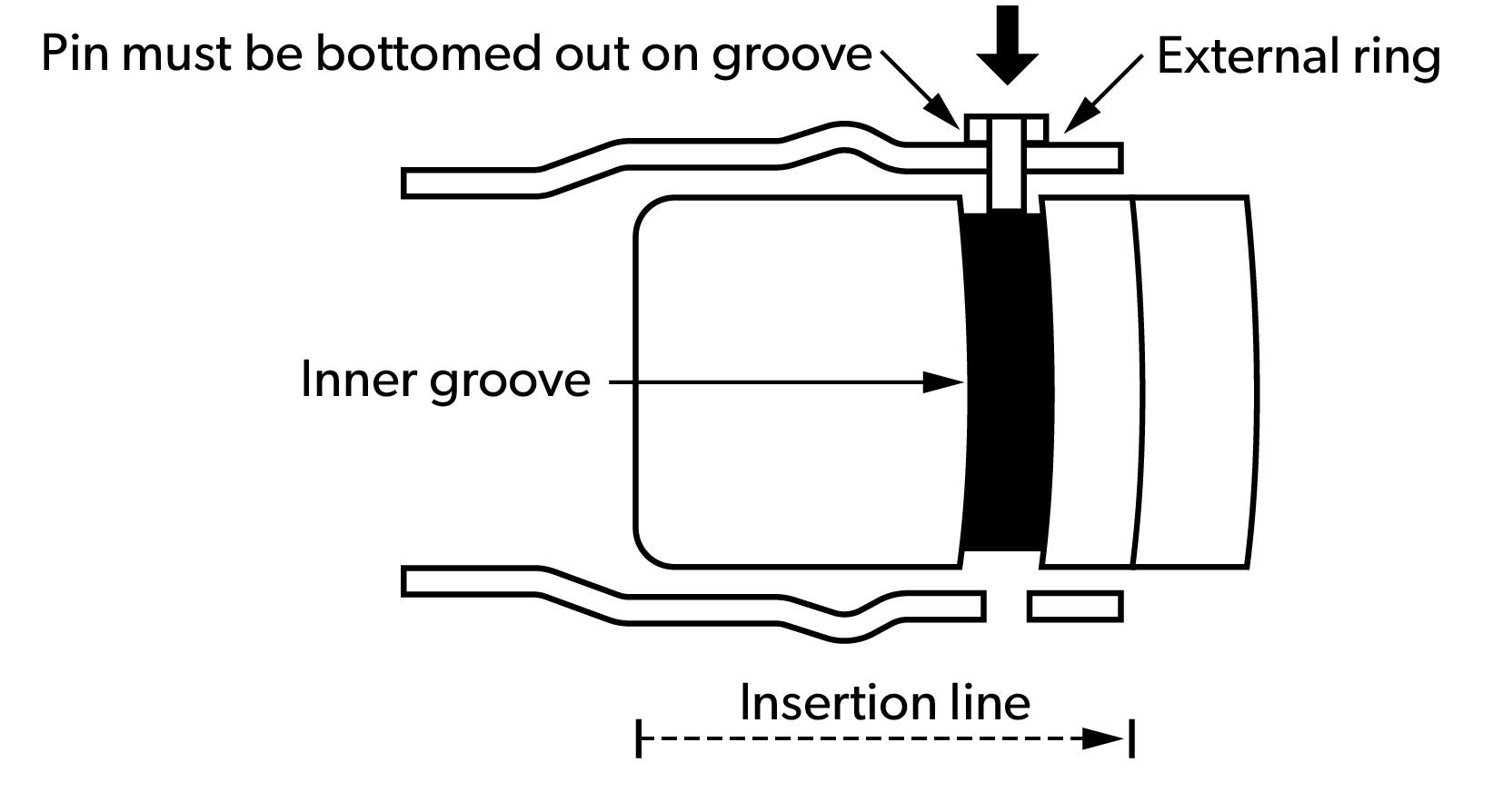
Pin-and groove joints for push-on joints
The figure below shows a pin-and-groove gasketed joint. In this joining system, when the pipe is assembled, a groove on the outside of the pipe spigot aligns with holes spaced around the pipe bell. Pins are hammered through an external ring, through the holes in the bell, and bottomed out in the spigot groove. Pin-and-groove (also known as ring-and-pin) joints have no metallic components.
Locking gaskets for push-on joints
Another internal restraint system for push-on joints is the use of proprietary locking gaskets. The restraint is engaged after the joint has been properly assembled including deflection. Pulling back on the joint will engage, or lock, the teeth in place. Restraint gaskets are an excellent option and are primarily used in smaller diameters (24-inch and down). This type of restraining system is primarily used for buried applications using ductile-iron push-on joints.
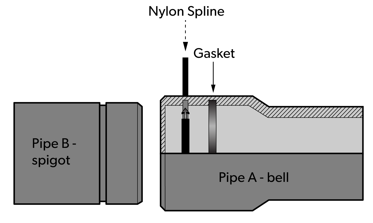
Spline-lock gasketed joint
The figure below shows a spline-lock gasketed joint. This joint uses a nylon locking spline that is inserted into mating grooves in the pipe spigot and the bell/coupling. Spline-lock joints form a non-metallic, mechanically restrained joining system that can be disassembled and reused if necessary.
Mechanical joint restraint design
Mechanical joints look similar to a flanged connection but unlike flanges, these joints use a gasket installed in a bell of the fitting. Manufacturers have several restraint joint designs for use with the mechanical joint system.
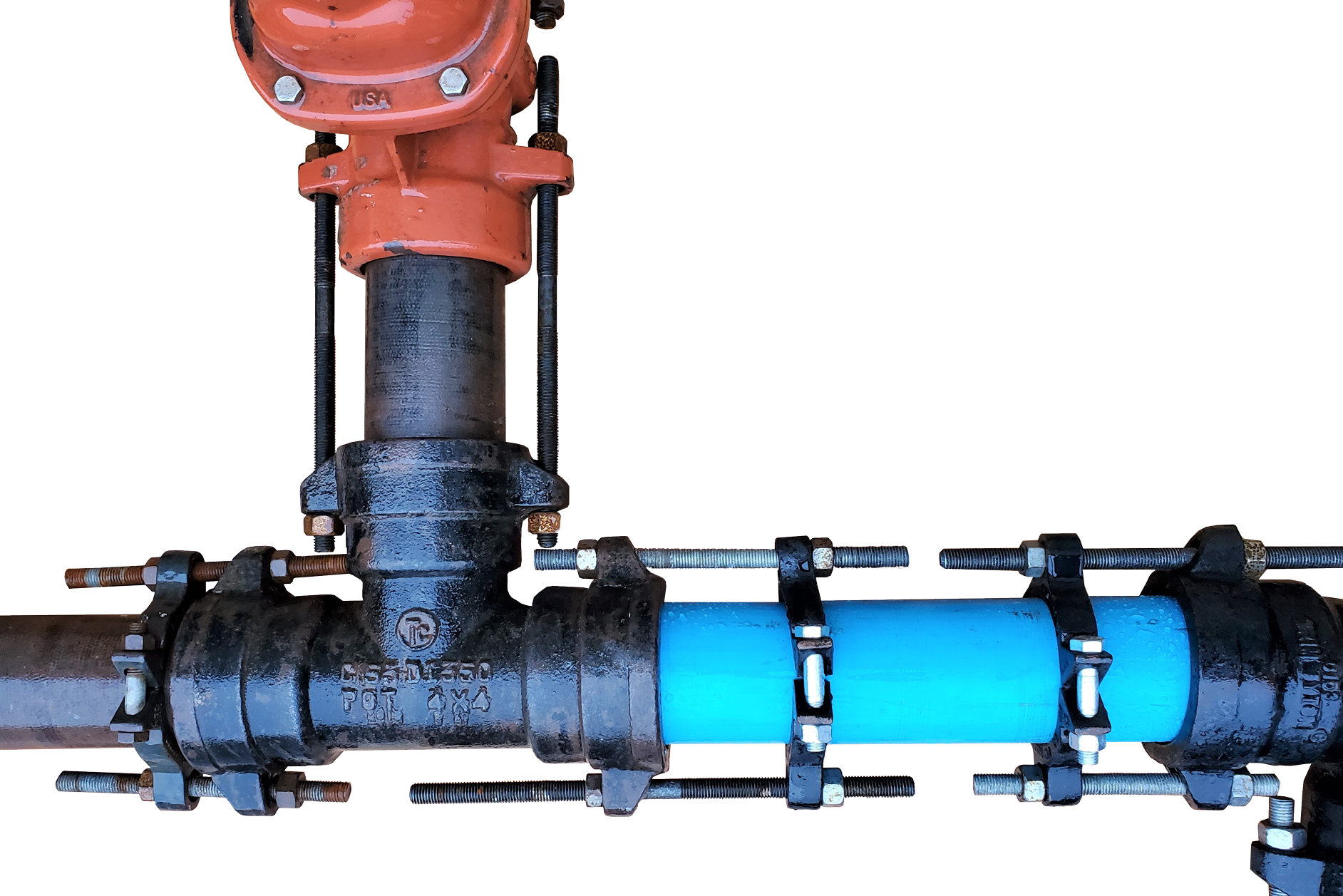
External ring restraint for mechanical joints
These joints have an external ring either welded onto the ductile iron pipe, or are a proprietary design that doesn’t require welding, for use on both ductile-iron and PVC piping. The design typically uses an additional gland set behind the ring to achieve the restraining capabilities.
Wedge action retainer for mechanical joints
The wedge action retainer is a mechanical joint restraining gland, incorporating a number of individually activated wedges located around the circumference of the pipe. This design allows for more deflection than traditional mechanical joints, and may be applicable for use in unstable soil conditions where small amounts of movement may occur.
Seismic-resistant joints
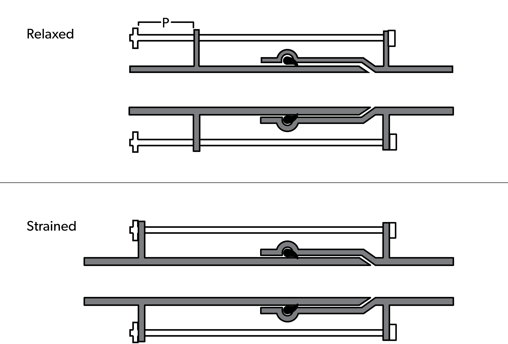
Some manufacturers of PVC pressure water pipe have joining systems that are designed to survive significant seismic events and permanent ground deformation. This unique design uses proprietary pipe connection that has lengthened bell ends that, when properly restrained, allow the pipe to extend in a chain-like fashion.
Installation Techniques for Ductile-Iron and PVC Piping and Fittings
Several steps must be done to complete the assembly and installation of underground piping. It is best practice to follow manufacturers instructions when completing the steps listed below.
- Pipe handling and storage
- Trench preparation.
- Cutting, bevelling, and chamfering the pipe
- Assembly techniques
- Deflection of the piping
- Tapping and service connections
- Bedding and backfill
Pipe Handling and Storage
Pipes can be distorted by improper storage such as improper handling and stacking, exposure to sunlight, and excessive heat or cold. Pipe and fittings stored outside for an extended period should be stored and supported as per the manufacturer’s instructions.
The following list gives guidelines for general pipe storage conditions:
- Exposure to excessive heat should be avoided to reduce the risk of pipe distortion.
- If plastic pipes or fittings are to be stored outdoors for extended periods of time, they should be protected as directed by the manufacturer. Plastic pipes may be affected by exposure to sunlight, especially if exposed for extended time periods and outside of protective cover.
- When purchasing pipe, check for damage such as deep scratches, cracked ends, out of round, etc.
- When receiving pipe, check for damage to the pipe, or shortages as compared to the bill of lading.
- When storing pipe, keep dirt and debris from getting into piping by leaving the protective caps and coverings on until the piping is installed.
- When stacking pipe at the job site, set the pipe on evenly spaced, level runners to prevent sagging. Place wedges or blocking to stop the pipe from rolling off the runners.
- Pipe delivered on pallets is often banded. Be sure that cutting the band does not cause the pipe stack to collapse uncontrolled. If the pipe is not on a supporting cradle, block the stack before cutting the banding.
- When stacking pipe that has hub ends, alternate the hub and spigot ends with the ends protruding so that the pipe barrels will lie flat.
- When unloading alongside a trench, stack the pipe on the opposite side of the trench from the excavated soil pile. Installing large and heavy pipe will be easier from the clean side of the trench
Trench Preparation
The drawings and bid documents will specify the correct line and grade to be established by the trenching operation. The trench depth will be deep enough to allow for the designer’s support system, the size of the piping, depth of coverage, and protection from the effects of freezing.
The BC Plumbing Code Article 2.3.5.1 indicates the minimum depth for underground piping is determined by the requirement for 300 mm (12 inches) of backfill material over the top of the pipe. Each jurisdiction in the province will have different minimum depths for the water service pipe to protect against freezing. BC Plumbing Code Article 2.3.5.3 simply states “Where piping may be exposed to freezing conditions, it shall be protected from the effects of freezing”. Plumbers should always check with the Authority Having Jurisdiction (AHJ) to ensure the pipe is buried to the correct depth.
The trench must be wide enough to permit proper installation of the pipe and to allow room to assemble joints and tamp backfill around the pipe. The width is governed by size of pipe, type of soil, and type of excavating equipment. A wider trench may be required if the installer intends to offset the pipe using joint deflection.
Refer to the “British Columbia Occupational Health and Safety Regulation Part 20: Construction, Excavation and Demolition” for trench shoring and requirements and safe sloping procedures.
De-watering of the trench may also need to take place. For safe and proper construction, the groundwater level in the trench should be kept below the pipe invert. This can be accomplished by the use of pumps placed in the trench.
Crossings
Where a watermain crosses a sanitary or storm sewer, the watermain should be laid to provide a minimum vertical distance of 0.45 metres between the outside of the watermain and the outside of the sewer. While the watermain may be either above or below the sewer, it is preferred that the water main be above the sewer. Locate one full length of water pipe at the crossing, so both joints will be as far from the sewer as possible. Special structural support for the water and sewer pipes may be required. If conflicts occur, provide additional protective measures.
Cutting, Bevelling, and Chamfering the Pipe
Most piping projects require pipe to be field-cut and bevelled (or chamfered) to allow for the installation of valves and fittings, etc. Although pipe is typically shipped with a bevel or chamfer on the end of the spigot, field cutting is regularly done by the installer, and therefore the bevel (or chamfer) must be created on the new spigot. For the purposes of this content, the terms bevel and chamfer are used interchangeably.
Depending on the type of joint, there are times when the installer must recreate a factory bevel after field cutting so the pipe’s spigot will correctly engage the sealing gasket. There are other times when the installer only needs to remove a sharp edge from the cut end of the pipe so the gasket will not be damaged. The decision on how much of a bevel to create depends on the connection to be made. A light bevel is adequate when the connection will be a mechanical joint, while a factory-replicated bevel is required for a push-on installation.
Although cutting and bevelling (chamfering) ductile-iron pipe and PVC pipe are similar, they use different tools and different techniques as described below.
Cutting and bevelling ductile-iron pipe
Field cutting of ductile-iron pipe is usually done with a gas-powered saw with abrasive wheel, or with an angle grinder. Using these power tools, it can take up to a minute per inch to cut the pipe. For example, it could take 16 minutes to cut a 16-inch diameter pipe. Care must be taken to ensure the pipe is cut square so the joint integrity is not compromised. An angle grinder, or hand file, can be used to bevel the spigot to the manufacturer’s specifications for push-on joints.
Cutting and bevelling PVC pipe
Field-cutting and bevelling of PVC can be done with power tools or with hand tools. As with ductile-iron pipe, a square cut is important. For smaller diameter pipes a mitre-box can be used with a hand saw to complete the cut. With large diameter pipes, it is common to use an abrasive disc or steel saw blade in a power tool. Take care not to cause burns.
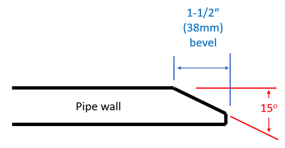
An angle grinder, power sander, rasp, or hand file are commonly used to bevel the spigot of PVC pipe to the manufacturer’s specifications for push-on joints. There are also specialty power tools that are designed to cut the bevel on plastic piping. For PVC pipe inserted into a PVC pipe bell or into a PVC fitting, match the pipe’s factory bevel. For PVC pipe inserted into a ductile-iron fitting, where the bells of iron fittings are much shallower than the bells of PVC fittings, the spigot should have only a slight bevel. Create the slight bevel at the end of the pipe by removing the sharp edge of the cut all the way around the outside edge.
The figure below shows an example of the dimensions for a factory bevel (chamfer) for installation into a PVC push-on fitting.
Assembly Techniques [Level 2]
Once the assembly process has begun, it is recommended to keep the three basic operations (digging, pipe laying and backfilling) as close together as practical. The shortest length of time a trench is open is the safest for all workers and reduces the possibility of problems associated with water, frozen ground, impact damage, flotation, and traffic.
Laying the pipe
It is good practice to lay ductile-iron and PVC pressure pipe with bells forward so that the assembly operation will consist of pushing the spigot into the bell. This will minimize the possibility of contaminating the surfaces with foreign material. Although rare, on occasion it may be necessary to lay pipe backward (bell into previously laid spigot end). This practice is normally not recommended due to the chance of dirt or debris compromising the joint. This method also requires extra care when backfilling and tamping as larger bell holes are generally required in the trench bottom to accommodate the assembly process.
Supporting underground pipe
The design of support of underground municipal water lines is normally done by engineers, or designed in accordance with good engineering practice. The specifications for a water supply system upstream of the water service pipe would include details on support for the different pipe and components that will be used. It is common for engineers, or other designated designers, to specify the support for the water service pipe for large ICI projects as well. If the drawings or specifications do not include information on underground water system piping support, then the plumber would make decisions based on the BC Plumbing Code Article 2.3.4.6., Support for Underground Horizontal Piping.
In the BC Plumbing Code Notes to Part 2, A-2.3.4.6.(1) shows permitted installations in Figure A-2.3.4.6.(1)(a). The methods of support shown in Figure A-2.3.4.6.(1)(b) are NOT permitted because the base does not provide firm and continuous support for the pipe.
Preparing the bell and spigot
For most pipes, gaskets are factory-installed. If the gasket is not pre-installed make sure that you are installing the correct gasket design for the type of pipe being used. Make sure that the gasket is clean and that the bell groove is free of any debris or dirt before positioning it into the groove in the bell. If the gasket is already installed it is usually not necessary to remove the gasket for cleaning. It is important to note that gaskets are not interchangeable between manufacturers, or between bell types.
Clean the inside of the bell (including the face of the gasket), and the outside of the spigot with a rag, brush, or paper towel to remove any dirt or foreign material before assembling. Apply a thin coating of lubricant (equivalent to a brushed coating) using a glove, a rag, or a paint brush. Most manufacturers recommend applying lubricant to the bevelled area of the spigot, as well as all around the entry lip of the bell and the face of the gasket. Use only manufacturer’s recommended pipe lubricant as the use of substitute lubricants may affect water quality or damage the gaskets.
Final assembly
There are differences between push-on joints and mechanical joints, so always follow the manufacturer’s installation requirements for the type of joint being installed.
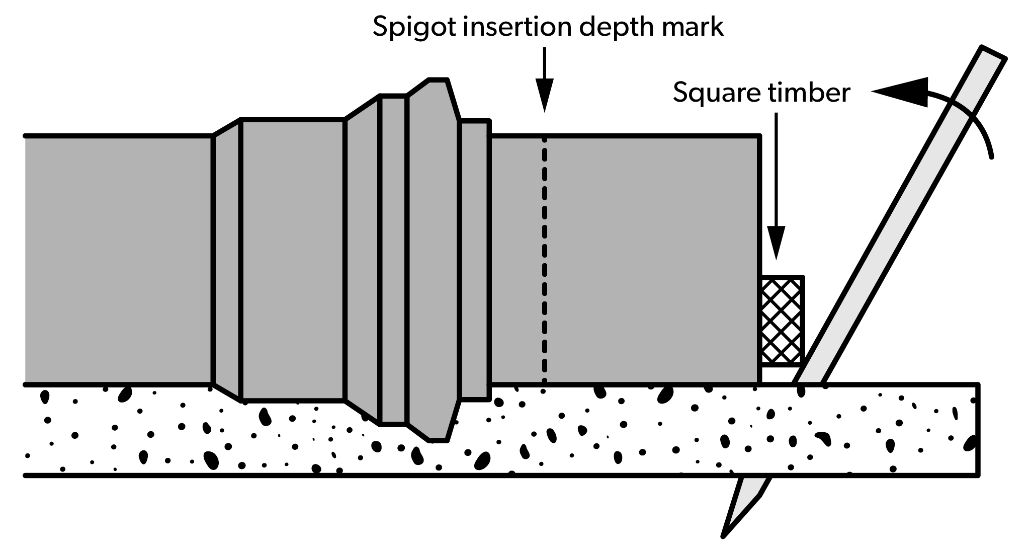
Keeping the spigot out of the dirt, position it so that the bevel is resting against the gasket in the bell. Push the spigot into the bell until the assembly line on the spigot is even with the edge of the bell. The assembly effort can be delivered by hand for small diameter piping with the aid of a twist as the spigot enters the bell, or by using a bar and block. Other assembly methods include lever pullers, come-alongs, hydraulic jacks, and specialty pipe pullers for large diameter pipes. Excavating equipment, such as backhoes, is often used to assemble large diameter piping systems. Extra care must be taken when using these types of equipment to ensure worker safety and prevent component damage.
Since ductile-iron fittings can be used with PVC pressure pipe, some special assembly methods are used. The bells of both mechanical joint and push-on ductile-iron fittings are much shallower than the bells of PVC pressure fittings. For this reason, the assembly line on the pipe spigot of the PVC pressure pipe is of no value as an indicator of proper assembly to ductile-iron fittings. In order to fully engage the gasket in the ductile-iron push-on bell, the factory bevel of the PVC pipe spigot should be reduced to only a slight bevel.
The figure below shows a bar being used to assist in the installation of the spigot into the bell of a push-on joint.
Where mechanical means, such as a backhoe, is used, the assembly effort should not be applied directly to the edge of the pipe. A two by four or a plank should be placed between the backhoe bucket and the edge of the pipe. Since the backhoe operator cannot clearly see when the assembly is complete, the installer must be in a position near the joint to signal when the assembly is complete.
Deflection of the Piping
If the piping assembly requires horizontal or vertical deflection, the necessary deflection can sometimes be done within the push-on or mechanical joint. Depending on pipe size, type of pipe, pipe joint design, coverage depth, and other parameters, manufacturers may allow for up to five degrees of deflection. A five-degree deflection equates to approximately 20 inches of offset for a 20-foot length of pipe.
When deflection is necessary, pipe should be assembled in a straight line, both horizontally and vertically, before deflection is made. To allow for deflection in push-on joints, the manufacturer recommends the installer assembles the joint but does not insert the spigot fully into the bell. It is recommended to push the spigot into the bell only to a point about 1/2 inch (13mm) short of the factory reference line (the first reference line if there are two). This assembly permits more movement of the end of the pipe at the bottom of the bell. For mechanical joints, assemble the joint in a straight line and then hand-tighten the bolts. Make the desired amount of deflection in the pipe and then complete the tightening of the bolts.
Tapping and Service Connections
The service connection, the connection of the water service pipe to the municipal water distribution system (water main), is required for almost every building served by the system. Although water purveyors prefer tapped couplings (tapped tees) there are other methods for making service connections to underground ductile-iron and PVC piping.
Direct tapping
Both ductile-iron and PVC piping can be direct tapped, where the corporation stop is threaded directly into the wall of the water main. This method is best performed using a power tool designed for the specific purpose of drilling and tapping pipe. Manufacturers make pipe tapping machines for ductile-iron and PVC pipe sizes from 4 inch to 48 inch. Some machines are even able to drill and tap under pressure, called hot-tapping.
Direct tapping PVC pressure pipe
For PVC pressure pipe, direct tapping is only recommended for specific sizes with specific DR ratings. For example, DR18 and DR14 pipe in sizes 6 inch (150 mm) through 12 inch (300 mm), conforming to AWWA C900 and CSA B137.3, can be direct tapped. The maximum size water service line connection for direct tapped PVC piping is 1 inch.
Corporation stops should be installed at least 2 feet (600mm) from the ends of PVC water main piping. Multiple taps should be separated by at least 18 inches (450mm) measured along the pipe length, and they should be staggered radially.
Direct tapping ductile-iron pipe
For ductile-iron pipe, the maximum recommended tap size for pressure class ductile-iron pipe is decided by class and pipe size. All classes of ductile-iron pipe 24 inches and larger in diameter can be direct tapped for 2-inch corporation stops. The cut-off at 2-inch diameter taps was chosen because most, if not all, tapping machines used to direct tap pressurized mains are limited to a maximum tap size of 2 inches.
The figure below shows a ductile-iron pipe that has been direct tapped.
Service saddles
As mentioned previously in this Learning Task, a service saddle is a threaded outlet that is attached to a larger diameter pipe, usually the water main, using straps, U-bolts, or brackets of various designs. Different materials, such as ductile-iron, brass, and stainless steel, are used based on the water purveyors’ specifications. Service saddles are available for any size or class of pipe. A service saddle is used to make connections up to a maximum size of 2 inch (50mm). Above this size a tapping sleeve, or tapped coupling, is required.
Tapping sleeves
Tapping sleeves are used to allow the branch line, or water service pipe, to be joined to the main using a connection at a metal sleeve that wraps around the pipe. One advantage to this system is the maximum branch line size, or water service pipe size, can be the same as the main size.
These fittings are suitable for making large taps in ductile-iron and PVC pressure pipe, but do require the use of a power operated tapping machine. Tapping sleeve installation may be sufficiently specialized to warrant the services of an expert contractor who can provide the necessary equipment.
Hot tapping (live tapping)
Water line hot tapping is a safe way to tie into an existing pressurized system. It is done by drilling into the pipe while it is under pressure, which completes a water line connection without having to interrupt the area around it. Once a saddle fitting has been added at the connection location, and the corporation stop has been installed, a special machine is required to complete the hot tap. The machine essentially drills a hole through the pipe wall using a special fitting installed into the stop valve. Most hot tapping machines work on the ductile-iron, PVC pressure pipe, and HDPE pipe used for municipal water mains.
The figure below shows stages of completing a hot tap. The left figure shows the hot tapping machine installed and ready to start the process. The centre figure shows the hot tapping machine drilling through the pipe wall through the open valve. The right figure shows the cutting tool retracted, with the pipe wall coupon removed with the cutting tool, and the valve closed. The machine is now ready to be removed so the water service pipe can be connected.
Bedding and Backfill
Municipal water supply system designers will include bedding and backfill specifications as part of the design package. The objective of bedding is to provide a continuous support for the pipe at the required line and grade. During installation, the projecting bells of the pipe should be properly relieved in the trench bottom so that the entire pipe is evenly supported by the bedding. Where the trench bottom is unstable (organic material) the trench bottom should be over-excavated and brought back to grade with approved material.
Design engineers will typically specify at least two different backfills, an initial backfill and a final backfill.
- Initial Backfill – The material placed over the pipe itself to a height of 6 to 12 inch (150mm – 300mm) above the top of the pipe is the initial backfill. The maximum size of stone in the initial backfill, where not specified, should be 1-1/2 inch (38mm). Where it is not otherwise specified, the initial backfill may consist of the native material in the trench provided it is free from large stones, not frozen, and free of debris or other organic materials. The purpose of the initial backfill is to protect the pipe from the final backfill.
- Final Backfill – The material placed over the initial backfill to the top of the trench is the final backfill. If not otherwise specified the final backfill material may contain stones up to 4 inch (100mm) in diameter and may consist of native material.
When plumbers install water service pipes, the BC Plumbing Code Article 2.3.5.1. covers a simplified version of backfilling of a pipe trench. It states that where piping is installed underground, the backfill shall be:
- carefully placed and tamped to a height of 300 mm over the top of the pipe, and
- free of stones, boulders, cinders and frozen earth.
BC Plumbing Code Notes to Part 2, A-2.3.5.1.(1) Backfilling of Pipe Trench states that “stronger pipes may be required in deep fill or under driveways, parking lots, etc., and compaction for the full depth of the trench may be necessary”. The Note also includes a figure similar to the one below, which shows details of the bedding and backfilling of pipe trenches.
Publisher: Open School BC]
Freeze Protection
The BC Plumbing Code Article 2.3.5.4., Protection Against Freezing, simply states “Where piping may be exposed to freezing conditions, it shall be protected from the effects of freezing.” The Notes to Part 2, A-2.3.5.4. indicate that the TIAC “Mechanical Insulation Best Practices Guide” is a comprehensive source of information on the selection, installation and proper use of thermal insulation materials. (Note that Section 4 of this Guide is not included in the scope of this Note as it contains information on proprietary products, which are not within the mandate of the Code.)
It is understood that exposure of piping systems to freezing conditions will cause water to freeze. The expansion of the water as it freezes can rupture the pipe. When the water thaws, the resulting damage can be extensive. In the context of the underground water service pipes that are installed by plumbers, installing the piping below the frost line, or insulating and heat tracing, are proven methods to prevent the water in pipes from freezing. These methods, along with frost boxes, will also work for the piping that gets exposed in the water meter box, if the water meter is installed close to grade at the property line.
The plumber Level One textbook, Line D, has a significant amount of content covering freeze protection.
Corrosion Control
The BC Plumbing Code Notes to Part 2, A-2.6.3.1. has some good content on water quality and corrosion control.
“Water destined for use as potable water can originate from a variety of sources that are generally classified as surface waters or well waters, such as lakes, rivers, streams and aquifers. In some localities, there may be seasonal variations in the water supply, and surface and well waters may be blended at times.
Water composition is the primary consideration in determining the cause of corrosion in potable water systems. If the water has corrosive characteristics, water treatment may be necessary to control its corrosiveness: this may be as straightforward as adjusting the pH of the water at the treatment plant, or it may involve more extensive corrosion-control treatment methods. Water purveyors normally consult treatment specialists to develop methods suitable for specific conditions. The treatment of water from private wells may also require expert consultation.
The past performance of plumbing materials and products in different localities often provides insight into what can be expected with new installations. In areas where water-related corrosion is known to occur, adjustment of water chemistry may be sufficient or it may be necessary to select alternative piping and fitting materials or more robust products.
It is important to note that not all corrosion can be attributed to water conditions: the improper design and installation of potable water systems may result in erosion corrosion, galvanic corrosion, fatigue cracking, and so forth.”
Water purveyors will make decisions on material selection based on the water quality and soil conditions in their jurisdiction. Common piping materials are ductile-iron, PVC, and HDPE, but fittings can be made from brass, stainless steel, and copper, among others. Water chemistry and velocity can cause erosion-corrosion as well as galvanic corrosion on the pipe inner wall, while dissimilar metals and soil conditions can case corrosion of the pipe outer walls.
In some jurisdictions, the ductile iron can be wrapped in a polyethylene sleeve. The sleeve of polyethylene completely wraps the pipe and the bell of any joints. The sleeve inhibits galvanic corrosion by physically separating the pipe from the surrounding soils.
PVC pipe is unaffected by electrolytic or galvanic corrosion, or any known corrosive soil or water condition. Tuberculation on the inner pipe wall is also not a concern, or the need for lining, wrapping, coating, or cathodic protection for the outer wall.
Testing and Disinfection
Testing and disinfection of potable water supply piping will be covered in the plumber level 4 content.
Now complete Self-Test 3 and check your answers.
Self-Test 3
Self-Test 3
- How can ductile-iron pipe and fittings be joined?
- Push-on joints only
- Mechanical joints only
- Push-on and mechanical joints
- Push-on, mechanical joints and flanged joints
- A push-on type joint uses a gasket that is installed in the spigot pipe end.
- True
- False
- What methods are used to resist damage to underground piping from thrust forces?
- Internal joint restraint only
- External joint restraint only
- Thrust blocks and thrust anchors only
- Thrust blocks, thrust anchors, and joint restraint
- When must PVC pipe be bevelled to match factory specifications?
- For push-on joints only
- For mechanical joints only
- For push-on and mechanical joints
- For push-on, mechanical, and flanged joints
- Using the tables in LT3, calculate the required thrust block area for the following specifications:
- 10″ – 90° Elbow
- 120 Psi Working Pressure
- Bedded in Sand
Answer = ft2
- Using the tables in LT3, calculate the required thrust block area for the following specifications:
- 12″ – Tee
- 90 Psi Working Pressure
- Bedded in Sand and Gravel cemented with Clay
Answer = ft2
- Using the tables in LT3, calculate the required thrust block area for the following specifications:
- 36″ – 45° Elbow
- 110 Psi Working Pressure
- Bedded in Sand and Gravel
Answer = ft2
- Using the tables in LT3, calculate the required thrust block area for the following specifications:
- 24″ – 90° Elbow
- 160 Psi Working Pressure
- Bedded in Sand and Gravel
Answer = ft2
- Using the tables in LT3, calculate the required thrust block area for the following specifications:
- 14″ – Tee
- 100 Psi Working Pressure
- Bedded in Soft Clay
Answer = ft2
Check your answers using the Self-Test Answer Keys in Appendix 1.
Image Attributions
- Figure 1 Comparison of SDR relationship by Camosun College is licensed under a CC BY 4.0 licence.
- Figure 2 Example of a stainless steel service saddle by Camosun College is licensed under a CC BY 4.0 licence.
- Figure 3 Mechanical coupling by Camosun College is licensed under a CC BY 4.0 licence.
- Figure 4 Repair clamp by Camosun College is licensed under a CC BY 4.0 licence.
- Figure 5 Plan view of typical thrust block locations in a municipal water supply system by Camosun College is licensed under a CC BY 4.0 licence.
- Figure 6 Typical thrust anchor installations by Camosun College is licensed under a CC BY 4.0 licence.
- Figure 7 Bell and spigot push-on connection ITA is licensed under a CC BY-NC-SA licence.
- Figure 8 Mechanical joint fitting by Camosun College is licensed under a CC BY 4.0 licence.
- Figure 8 Ductile-iron flanged fitting by Camosun College is licensed under a CC BY 4.0 licence.
- Figure 10 An external joint restraint for ductile-iron fittings with restraining ears by Camosun College is licensed under a CC BY 4.0 licence.
- Figure 11 An example of pin-and-groove joint restraint for PVC connections by Camosun College is licensed under a CC BY 4.0 licence.
- Figure 12 An example of spline-lock internal joint restraint for PVC connections by Camosun College is licensed under a CC BY 4.0 licence.
- Figure 13 A cutaway of one version of the external ring restraint system by Camosun College is licensed under a CC BY 4.0 licence.
- Figure 14 How a seismic-resistant joint allows for movement in the piping by Camosun College is licensed under a CC BY 4.0 licence.
- Figure 15 Bevel dimensions for pipe spigot by John Gordon is licensed under a CC BY-NC-SA licence.
- Figure 16 Push-on fitting assembly technique by Camosun College is licensed under a CC BY 4.0 licence.
- Figure 17 Plan view of a push-on joint being deflected by Camosun College is licensed under a CC BY 4.0 licence.
- Figure 18 A ductile-iron pipe that has been direct tapped by Camosun College is licensed under a CC BY 4.0 licence.
- Figure 19 The hot-tapping process by Camosun College is licensed under a CC BY 4.0 licence.
- Figure 20 Backfilling a trench by ITA is licensed under a CC BY-NC-SA licence.
