Learning Task 2
Describe Sizing for the Building Water Supply System
The proper sizing and installation of potable water distribution systems in residential and small commercial applications is critical to proper operation of the plumbing fixtures and equipment installed within the building. The potable water system must be capable of meeting the peak water supply demands of the connected fixtures and appliances. Each fixture or appliance requires a minimum supply pressure and flow rate; if the system fails to maintain these conditions, the fixture or appliance may not adequately perform its intended function. An undersized cold water pipe to a washroom group of fixtures could lead to an excessive pressure drop upon operation of a water closet, which could lead to an adjacent shower valve suddenly being starved of cold water, which could lead to scalding. Similarly, an excessive pressure drop due to flow to other fixtures could lead to a flush valve fixture failing to function properly.
Terminology
Peak Water Supply Demands
Each fixture, device, or appliance is given a fixture unit value, referred to as a water supply fixture unit to differentiate from DWV fixture units. The peak demand flow is the total of all the fixture unit values if all fixtures were used at once, including any additional load for a fire sprinkler system, irrigation system or any other demands on water service.
Minimum Supply Pressure
Every building water distribution system will have one fixture that requires more pressure than the others to operate correctly. This fixture is referred to as the “governing fixture.” The BCPC Sentence 2.6.3.1. (1) states that the “water distribution systems shall be designed to provide peak demand flow when the flow pressures at the supply openings conform to the plumbing supply fitting manufacturer’s specifications.” This means that the plumber must determine the minimum pressure required for the governing fixture by using the manufacturer’s specifications.
In past BC Plumbing Codes, the minimum pressure for common fixtures was listed on Table 2.6.3.2.-A along with the fixture unit load. In previous codes, fixtures such as clothes washers, dishwashers and direct flush valves required a minimum flow pressure of 15 psi (approximately 105 kPa) at the fixture to operate properly. Therefore, when the manufacturer’s specifications cannot be used – because the make and model of the fixture are unknown, for example – the plumber should still use 15 psi (approximately 105 kPa) when calculating water pipe sizing.
Pressure Drop
Pressure drop in a water supply system is difference between pressure at the upstream end of a pipe and the pressure delivered to a fixture of device. Pressure loss will occur in water pipe due several factors, including:
- The type of pipe material
- The age of the pipe
- The size of the pipe
- The number and type of fittings
- The velocity of the water
- The temperature of the water
Pressure drop is pressure loss due to friction, or friction loss, and is anticipated by designers and can be accommodated in the pipe sizing process. Although friction loss was previously discussed during the selection of circulator pumps for DHWR systems, it will be covered again as the size of water supply piping is dependent on the friction created by the piping material. For example, water flowing through a relatively large, smooth pipe at low velocity has laminar, or a smooth, streamlined flow. At the other extreme, when the pipe is small in diameter with a rough interior, and the velocity of the water is high, the flow is turbulent. Laminar flow produces little friction, while turbulent flow can produce considerable friction.
Friction loss in water piping is also referred to as head loss due to the fact that the friction loss is equated to the loss of pressure measured in feet [JG1] per 100 feet of piping material being used. It is important to note that flow rates substantially increase the head loss within the piping system. Head loss or friction loss increases as pipe ages and internal wall conditions of the piping material change.
Flow Rate
Flow rate is the volume of water delivered to a fixture of device. Flow rate is dependent on water velocity and the size of the pipe. The following formula shows the relationship between flow rate, pipe size and water velocity.
Q = A × V
Where:
- Q = Quantity (flow rate in cubic feet per sec)
- A = Area of the pipe in square feet (this is the size of the pipe)
- V = Velocity of the water in feet per sec.
A steady rate of flow means that equal quantities of water flow past every point in the system during a given period of time. This means that in a water distribution system design using larger pipes upstream, and smaller pipes as the fixture unit load decreases, the velocity of the water in the pipes will be different. To have the same amount of water flow through a small pipe as through a larger pipe in the same length of time, the velocity will have to increase. The designer needs to ensure the velocity of the water in the piping system does not exceed the manufacturer’s limits. The maximum velocity will be different for different materials, as well as for different water temperatures.
Water conservation
The BC Plumbing Code lists the maximum flow rates for lavatory supply fittings, kitchen supply fittings, and shower heads in Table 2.2.10.6. Water usage per flush cycle for water closets is listed in Table 2.6.1.6 of the BCPC. Many municipalities have chosen to introduce their own water conservation bylaws and require more restrictive water use measures. Different building construction methods such as LEED, Passive House Design, BC Step Code also require more restrictive water use.
Water Velocity
Since the BC Plumbing Code Sentence 2.6.3.5. (1) simply states that the maximum permitted water velocities shall be those recommended by the pipe and fitting manufacturer, the table below has been compiled to show the water velocity limits for common water distribution system materials.
Recommended water velocity limits for common water distribution system materials
| Temperature | Maximum velocity (meters per second/feet per second) |
|---|---|
| COLD (unheated) | 3.0 mps/10 fps |
| HOT up to and including 140°F (60°C) | 2.4 mps/8 fps |
| HOT above 140°F (60°C) | 1.5 mps/5 fps |
| DHW Recirculation system (recommended) | 0.6 mps/2 fps |
| Temperature | Maximum velocity (meters per second/feet per second) |
|---|---|
| COLD (unheated) | 2.4 mps/8 fps |
| HOT up to and including 140°F (60°C) | 1.5 mps/5 fps |
| HOT above 140°F (60°C) | 0.9 – 1.2 mps/3 – 4 fps |
| DHW Recirculation system (recommended) | 0.6 mps/2 fps |
| Temperature | Maximum velocity (meters per second/feet per second) |
|---|---|
| COLD (unheated) | 2.4 mps/8 fps |
| HOT up to and including 140°F (60°C) | 2.4 mps/8 fps |
| HOT above 140°F (60°C) | 2.4 mps/8 fps |
| Temperature | Maximum velocity (meters per second/feet per second) |
|---|---|
| COLD (unheated) | 2.4 mps/8 fps |
| HOT up to and including 140°F (60°C) | 2.4 mps/8 fps |
| HOT above 140°F (60°C) | 2.4 mps/8 fps |
| Material | Maximum velocity (meters per second/feet per second) |
|---|---|
| Stainless steel | 2.0 mps/6.5 fps |
| Ductile iron | 4.3 mps/14 fps |
Building Water Supply System Design Considerations
The BCPC Subsection 2.6.3. Size and Capacity of Pipes introduces the designer to some important information regarding pipe sizing for potable water service pipes and water distribution systems.
Of particular importance is Sentence 2.6.3.1.(2), which states that “potable water systems shall be designed, fabricated and installed in accordance with good engineering practice, such as that described in the ASHRAE Handbooks and ASPE Data Books.” This Sentence refers to Note A-2.6.3.1.(2) in the Notes to Part 2. The Note lists several documents that are considered good engineering practice in the field of potable water systems, but adds an alternative method. The alternative to a detailed engineering design method is to use Table A-2.6.3.1.(2)-A (Small Commercial Building Method) and Table A-2.6.3.1.(2)-F (Average Pressure Loss Method).
The BCPC allows for another method of pipe sizing described in Sentence 2.6.3.4.(5), which states: “Where both hot and cold water is supplied to fixtures in residential buildings containing one or two dwelling units or row houses with separate water service pipes, the water system may be sized in accordance with Table 2.6.3.4.”
Interpreting this information, it can be concluded the BCPC allows for four methods of sizing the building water supply system:
- Simplified method for buildings containing one or two dwelling units or row houses with separate water services
- Small commercial building method
- Average pressure loss method
- Detailed engineering design method
Each of these methods has a similar process to go through to come up with the minimum pipe size for each section of a water supply system. Depending on the building type, the plumber could use any of the methods, but is unlikely to use the detailed engineering design. The detailed engineering design method allows designers like engineers to use design standards that aren’t readily available to a plumber. To help plumbers use the sizing methods in the BCPC, the Notes to Part 2 section goes through a sizing example for each method.
- Note A-2.6.3.1.(2) goes through the Method for Small Commercial Buildings’, as well as the Average Pressure Loss Method.
- Note A-2.6.3.4.(5) covers sizing using the simplified method
Information to help understand water supply system pipe sizing diagrams and drawings is required. The topics on the list below will be explained in more detail in this section.
- Common abbreviations and terminology used on water pipe sizing diagrams
- BC Plumbing Code Table 2.6.3.2.-A
- Water supply fixture unit definition
- Fixture or Device column
- Minimum Size of Supply Pipe, inches
- Private Use Hydraulic Load, fixture units and Public Use Hydraulic Load, fixture units
- Cold, Hot, Total columns
- Direct flush valve WSFU values
- Table 2.6.3.2.-D
- Developed length
- Pressure loss/gain due to elevation
- Pressure loss due to friction
- Minimum pressure required
- Maximum design velocity for piping material
Common Abbreviations and Terminology Used on Diagrams
WSP - for the Water Service Pipe. This pipe conveys water from a public or private water system into the building.
WDP - for the Water Distribution Pipe. This pipe conveys water from the WSP to the fixtures or devices. These pipes can be further described by the abbreviation HWDP for hot water piping, and CWDP for cold water piping.
SP - for Supply Pipe. This pipe is part of the water distribution system that supplies a single fixture. This is the WDP that usually protrudes through the floor or wall, and to which a shut-off valve or tail piece adapter is attached.
Tailpiece or Connector - This component is a flexible connector that conveys water from the Supply Pipe to the fixture
Common fixture abbreviations:
- BT = Bathtub
- CW - Clothes Washer
- DW = Dish Washer
- FU = Fixture Unit
- HB = hose bibb
- HWH = Hot Water Heater
- KS = Kitchen Sink
- Lav = Lavatory
- LT = Laundry Tray
- FTWC = Flush Tank Water Closet
BC Plumbing Code Table 2.6.3.2.-A
Plumbers and building water supply system designers need to determine the quantity of potable water that will be used by each fixture or device that is installed in the building. The BCPC Table 2.6.3.2.-A, Sizing of Water Distribution Systems, is an extensive list of fixtures and devices that require domestic water. To use the table, the plumber needs to interpret the column headings correctly to ensure the correct WSFU value is selected. The table headings and table values are described here.
Water supply fixture unit (WSFU)
The Code defines a fixture unit (as applying to water distribution systems) as the unit of measure based on the rate of supply, time of operation and frequency of use of a fixture or outlet that expresses the hydraulic load that is imposed by that fixture or outlet on the supply system. Since the term fixture unit is also used in the DWV system, the abbreviation WSFU is commonly used to indicate water supply fixture units.
The purpose of having fixture units is to ensure that every designer using the BC Plumbing Code for water supply system pipe sizing is using the same values for fixtures or devices. This will reduce the probability of inappropriate assumptions regarding hydraulic loads, which reduces the probability of undersized water supply system piping.
Table 2.6.3.2.-A is used to determine the WSFU load for most fixtures and devices. However, a note located below the table, refers the designer to Table 2.6.3.2.-D. for fixtures not indicated in Table 2.6.3.2.-A. Using these two tables, it is possible to come up with a WSFU load for almost every fixture or device.
Fixture or device
A fixture is defined in the BCPC as a receptacle, appliance, apparatus or other device that discharges sewage or clear-water waste and includes a floor drain, while a device is defined as a piece of equipment or a mechanism designed to serve a special purpose or perform a special function
Most fixtures and devices that use potable water are listed on BCPC Table 2.6.3.2.-A. Some fixtures have different designs that change their WSFU value, so will have multiple rows on the table. An example of a fixture with multiple rows is a sink:
- Sink, bar
- Sink, clinic service faucet
- Sink, clinic service wit h direct flush valve
- Sink, kitchen commercial, per faucet
- Sink, kitchen domestic, 8.3 LPM
- Sink, kitchen domestic, greater than 8.3 LPM
- Sink, laboratory
- Sink, laundry (1 or 2 compartments)
- Sink, service or mop basin
- Sink, washup
The plumber or designer needs to accurately determine the design of fixtures to ensure the correct WSFU value is selected from the table.
Note that the “Bathroom Group” (BG) fixture load options on Table 2.6.3.2.-A may be acceptable, but adds complexity to design. When using the BG WSFU loads, it is important to know that the value on the table is based on a ½-inch size bathtub supply pipe. If a bathtub with a larger load is installed, the BG load may not work. Also, the three standard fixtures that make up a BG are a water closet, lavatory and bathtub. If an additional fixture is installed so there are more than the three standard fixtures, the additional fixture load must be added to the bathroom group.
Note that the hydraulic load of urinals and water closets with direct flush valves shall be the number of fixture units listed in Tables 2.6.3.2.-B and 2.6.3.2.-C. of the BCPC. There is an example of these tables and interpreting the decreasing values later in this content.
Minimum size of supply pipe, inches
A supply pipe is the water distribution pipe that delivers water to only one fixture or device. Table 2.6.3.2.-A lists the size of the supply pipe for individual fixtures or devices, even allowing [latex]\dfrac{3}{8}[/latex] inch size for some. The table uses inside diameter (ID) sizes which means the [latex]\dfrac{3}{8}[/latex] inch pipe listed is actually [latex]\dfrac{1}{2}[/latex] inch outside diameter (OD). This size pipe is not a common pipe size for plumbers. The smallest diameter commonly used for water distribution systems is [latex]\dfrac{5}{8}[/latex] inch OD, which plumbers refer to as [latex]\dfrac{1}{2}[/latex] inch copper pipe.
Private use hydraulic load, fixture units and public use hydraulic load, fixture units
The table uses the terms “private use” and “public use” fixtures to differentiate between the type of use in different buildings. This means the plumber must decide which column to use when determining WSFU values.
- Private use means fixtures in residences and apartments, in private bathrooms of hotels, and in similar installations in other buildings for one family or an individual.
- Public use means fixtures in general washrooms of schools, gymnasiums, hotels, bars, public comfort stations and other installations where fixtures are installed so that their use is unrestricted.
Cold, hot, total columns
Fixtures can be supplied by cold water only, such as water closets and urinals, or can be supplied by hot water only, such as dishwashers, but many fixtures are supplied by both cold and hot water. The table has separate columns for cold and hot WSFU values, but these columns are only used when completing a detailed engineering design method. Plumbers will therefore only use the column indicating the total WSFU value for each fixture.
The plumber must not combine the WSFU load from the cold with the WSFU load from the hot as this would “double count” the WSFU load. The combined load at the fixture or device is determined by the maximum load at the spout, or the opening the water flows through at the fixture or device.
An example of the WSFU load for a public use lavatory, with greater than 8.3 LPM of flow, is shown in the figure below.
For this example, if only the cold water was turned on the spout would allow 2 WSFU of flow, and if only the hot water was turned on the spout would allow 2 WSFU of flow. If both the cold and hot water were turned on the spout would still only allow 2 WSFU of flow, some from the cold and some from the hot.
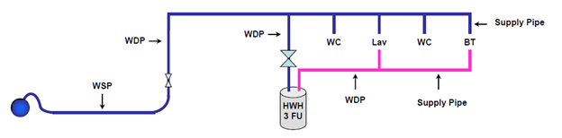
An example of a simple building water distribution system is shown below. The sketch shows the piping layout and the location of the fixtures, while labels indicate the type of fixture. A separate legend gives more information on the fixtures and devices to help with the use of Table 2.6.3.2.-A when determining WSFU loads for fixtures and combined pipes.
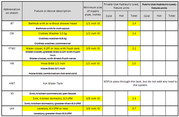
The table below, based on the example sketch above, shows the decisions a plumber would need to make when selecting fixtures and deciding on WSFU values.
| Abbreviation on sketch | Fixture or device description | Minimum size of supply pipe, inches | Private Use Hydraulic Load, fixture units Public Use Hydraulic Load, fixture units |
||
|---|---|---|---|---|---|
| Cold | Hot | Total | |||
| BT | Bathtub with or without shower head Bathtub with ¼ inch spout |
½ inch ID | 1.4 | ||
| CW | Clothes Washer 3.5 kg Clothes washer 6.8 kg Clothes washer, commercial |
½ inch ID | 1.4 | ||
| FTWC | Water closet, 6 LPF or less with flush tank Water closet, greater than 6 LPF with flush tank Water closet, with direct flush valve |
[latex]\frac{3}{8}[/latex] inch ID | 2.2 | ||
| HB | Hose Bibb ½ inch Hose Bibb ¾ inch Hose bibb, combination hot and cold |
½ inch ID | 2.5 | ||
| HWT | Hot Water Tank | WSFUs pass through the tank, but do not add any load to the system. | |||
| KS | Sink, kitchen commercial, per faucet Sink, kitchen domestic, 8.3 LPM Sink, kitchen domestic, greater than 8.3 LPM |
[latex]\frac{3}{8}[/latex] inch ID | 1.4 | ||
| LAV | Lavatory, 8.3 LPM or less Lavatory, greater than 8.3 LPM |
[latex]\frac{3}{8}[/latex] inch ID | 0.7 | ||
Direct flush valve WSFU values
Water closets can be designed to use a flush tank or a direct flush valve, and urinals are designed to use a direct flush valve in almost every case. Direct flush valves require a significant flow of water to create the flushing and cleaning action they perform in the few seconds they are open. For example, this means that the minimum supply line size of a direct flush valve WC is larger than the supply line for a tank-type WC, as shown on BCPC Table 2.6.3.2.-A.
The BCPC Code has two separate tables to help plumbers design a water distribution system that includes direct flush valves. Table 2.6.3.2.-B is titled “Sizing of Water Distribution Systems for Urinals with Direct Flush Valves” and Table 2.6.3.2.-C is titled “Sizing of Water Distribution Systems for Water Closets with Direct Flush Valves”.
The figure below is a piping system sketch showing an interpretation of decreasing values from Table 2.6.3.2.-B for urinals with direct flush valves and Table 2.6.3.2.-C for water closets with direct flush valves.
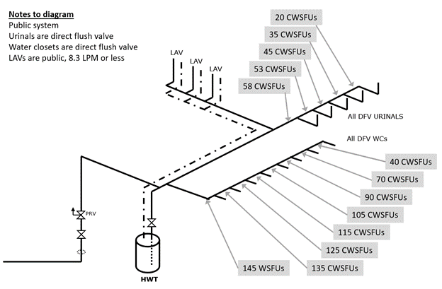
Table 2.6.3.2.-D
This table is used when the fixture or device is not listed on Table 2.6.3.2.A. Manufacturer’s literature will need to be used to determine the size of the supply pipe before a hydraulic load can be selected.
Developed Length
The BCPC defines developed length as “the length along the centre line of the pipe and fittings.” When using some water pipe sizing tables in the BCPC, the plumber will need to choose a column of maximum allowable length based on the developed length of the water supply piping. If the water supply system does not use a pressure-reducing valve inside the building, the developed length upstream end is considered to be at the property line. If the water supply system uses a pressure-reducing valve inside the building, then the developed length upstream end starts at the outlet of the PRV. This is because the PRV essentially creates a new pressure zone.
Pressure Loss/Gain due to Elevation
Pressure is highest as it enters the building through the water service pipe. As water flows downstream, there are several losses from components that must be subtracted from the incoming pressure, such as the water meter, a pressure reducing valve, or a backflow prevention device. The incoming water must also flow to the highest fixture in the building. Pressure loss will occur as the water gains elevation, but pressure increase will occur if the water travels to a fixture below the water service pipe. Pressure gain and loss is based on the weight of water. Pressure will decrease 0.433 psi per foot of elevation gain (10 kPa per meter) or increase 0.433 psi per foot of elevation loss. The figure below shows how pressure at fixtures will be reduced based on elevation gain.
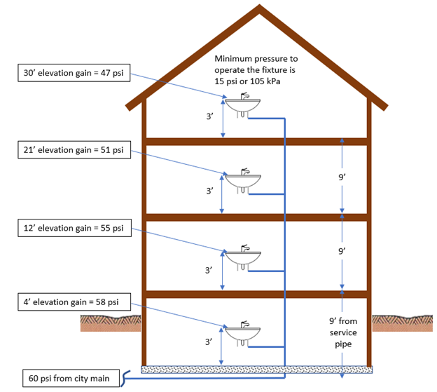
Note that the incoming pressure of 60 psi was reduced to 47 psi because of the pressure loss due to a change of elevation of 30 feet.
Pressure Loss due to Friction
Friction loss in piping was previously discussed in the section on hot water circulator pump selection, and is also described in the Terminology section above. Friction causes pressure loss in pipe and fittings and can be thought of as the pressure-difference-per-foot needed to push the water along at the required flow rate. The designer will need to ensure that the pressure loss due to friction does not exceed the maximum allowable for the pipe size and type used in the water distribution system.
Minimum Pressure Required
The minimum pressure required is determined by the governing fixture or device as described in the Terminology section above. Unless a specific minimum pressure is known, the plumber should use 15 psi (approximately 105 kPa) when calculating water pipe sizing.
Maximum Design Velocity for Piping Material
Maximum design velocity for piping material is described in the Terminology section above. The plumber will need to consider the water velocity when sizing piping in the building water distribution system. Some pipe sizing tables in the BCPC will require the plumber to choose a section of the table based on water velocity. The maximum water velocity will depend on the type of piping material and the temperature of the water flowing through the piping. Some commonly used velocities for residential water distribution piping are listed here:
- PEX pipe with cold unheated water = 3.0 m/s (10 f/s)
- PEX pipe with hot water up to and including 60°C (140°F) = 2.4 m/s (8 f/s)
- PEX pipe above 60°C (140°F) = 1.5 m/s (5 f/s)
- Copper pipe with cold unheated water = 2.4 m/s (8 f/s)
- Copper pipe with hot water up to and including 60°C (140°F) = 1.5 m/s (5 f/s)
- Copper pipe above 60°C (140°F) = 1.2 m/s (4 f/s)
Sizing Residential and Small Commercial Water Supply Systems
Recall that there are four methods for sizing the building water supply system. Since the detailed engineering design is done using ASHRAE Handbooks and ASPE Data Books, a plumber will use one of the other three methods listed here:
- Simplified method
- Small commercial building method
- Average pressure loss method
When using any of the methods, it is advisable to have a worksheet to help pull together all the important information. Some options for worksheets are shown below, based on the sizing method chosen.
Note that the BCPC Sentence 2.6.3.4.(1) states that water service pipes shall be sized according to the peak demand flow but shall not be less than ¾ inch (19mm) in size.
Simplified method
The BC Plumbing Code includes an example of this method using Figure A-2.6.3.4.(5)-B and Tables 2.6.3.2.-A, -B, -C and -D. A “Fixture Units Summary” is included and is a good example of a worksheet that should be used to collect all the WSFU values for fixtures or devices. Other worksheets, for the water service pipe, the hot water piping sizes, and the cold water piping sizes, are also included. The worksheets for this method include several water velocities for different materials. The example below is of how a worksheet could be used for the simplified system example in the BCPC if the building water supply system was constructed using PEX material.
| Pipe or tube identifier | Cold or hot piping | WSFU load | Notes | Maximum water velocity based on material | Pipe or tube size |
|---|---|---|---|---|---|
| 1 | Hot | 3.5 | blank | 2.4 m/s (8 ft/s) | ½″ |
| 2 | Hot | 6.3 | blank | 2.4 m/s (8 ft/s) | ½″ |
| 3 | Hot | 8.4 | blank | 2.4 m/s (8 ft/s) | ¾″ |
| 4 | Hot | 2.1 | blank | 2.4 m/s (8 ft/s) | ½″ |
| 5 | Hot | 6.3 | blank | 2.4 m/s (8 ft/s) | ½″ |
| 6 | Hot | 14.7 | blank | 2.4 m/s (8 ft/s) | ¾″ |
| A | Cold | 1.4 | blank | 3 m/s (10 ft/s) | ½″ |
| B | Cold | 5.7 | blank | 3 m/s (10 ft/s) | ½″ |
| C | Cold | 5.7 | blank | 3 m/s (10 ft/s) | ½″ |
| D | Cold | 11.4 | blank | 3 m/s (10 ft/s) | ¾″ |
| E | Cold | 14.7 | blank | 3 m/s (10 ft/s) | ¾″ |
| F | Cold | 19.1 | blank | 3 m/s (10 ft/s) | 1″ |
| G | Cold | 19.1 | blank | 3 m/s (10 ft/s) | 1″ |
| H | Cold | 21.3 | blank | 3 m/s (10 ft/s) | 1″ |
| I | Cold | 23.8 | blank | 3 m/s (10 ft/s) | 1″ |
| J | Cold | 2.8 | blank | 3 m/s (10 ft/s) | ½″ |
| K | Cold | 3.6 | blank | 3 m/s (10 ft/s) | ½″ |
| Water service pipe | Cold | 23.8 | PEX from curb stop to building | 3 m/s (10 ft/s) | 1″ |
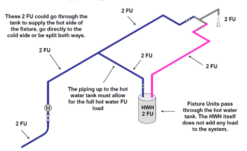
The simplified method example in the BCPC Notes has an HWT that is supplied by cold water after several cold water branches have already drawn water for fixtures. The location of the HWT in the water distribution system can make the WSFU load counting complex. The WSFU load added for the HWT depends on the location of the hot water tank. Unfortunately, the BCPC is not clear on how to add the WSFU loads for the different HWT locations.
The figure below shows three locations for the HWT to be connected to the CWDP: most upstream, most downstream, and somewhere in between. Each example shows the correct addition of the WSFU loads.
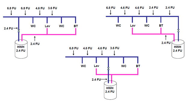
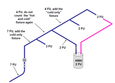
If the HWT is the most upstream, WSFU addition is straight forward. If the HWT is the most downstream or somewhere in the middle, it is best to think of it as the most upstream and then add in only the fixtures supplied with cold-only that are downstream of the connection, and continue adding in the cold-only fixture loads moving upstream from the HWT. The figure below shows this method so that the HWT load is not doubled-counted.
Small commercial building method
The BC Plumbing Code Figure A-2.6.3.1.(2)-A is an example of the water supply system for a commercial and residential development and is used with the small commercial building pipe sizing method.
Table A-2.6.3.1.(2)-A, Pipe Sizes for Water Systems Based on Number of Fixture Units Served Using the Small Commercial Method, is used for this method.
To use the table, the plumber will need to separate the water service pipe and the cold and hot distribution systems into separate sections when determining the developed length and the minimum static pressure.
The water service pipe:
- The minimum static pressure is the pressure available at the property line, including all pressure losses for the water service. The water supply pipe does not generally have many losses as the components that create the losses are installed after the water service pipe enters the building. Losses or gains due to changes in elevation, and friction loss, may need to be considered.
- The developed length is measured from the property line to the point of entry.
The cold and hot distribution systems:
- The minimum static pressure is the pressure available once the water service pipe enters the building. Losses for water meters, pressure-reducing valves, backflow preventers, water treatment systems, and any other devices need to be considered.
- The developed length is measured from the water service entry point to the building to the most remote water outlet.
The small commercial building method includes a Fixture Units Summary and is a good example of a worksheet that should be used to collect all the WSFU values for fixtures or devices. The example in the BCPC also has good examples of tables for sizing each section of the system, divided into the water service pipe, the hot water distribution system and the cold water distribution system.
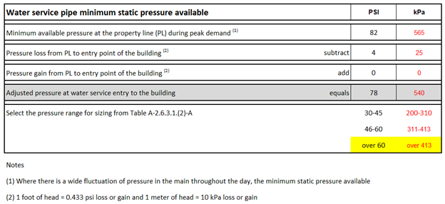
The worksheet below shows an example of determining the minimum static pressure available for the water service pipe when using the small commercial building method.
| Water service pipe minimum static pressure available | PSI | kPa |
|---|---|---|
| Minimum available pressure at the property line (PL) during peak demand[1] | 82 | 565 |
| Pressure loss from PL to entry point of the building[2] | subtract 4 | subtract 25 |
| Pressure gain from PL to entry point of the building[3] | add 0 | add 0 |
| Adjusted pressure at water service entry to the building | equals 78 | equals 540 |
| Select the pressure range for sizing from Table A-2.6.3.1.(2)-A | 30-45 46-60 over 60 |
200-310 311-413 over 413 |
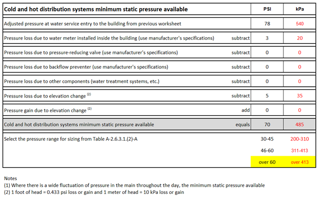
The worksheet below shows an example of determining the minimum static pressure available for the cold and hot water distribution systems when using the small commercial building method.
| Cold and hot distribution systems minimum static pressure available | PSI | kPa |
|---|---|---|
| Adjusted pressure at water service entry to the building from previous worksheet | 78 | 540 |
| Pressure loss due to water meter installed inside the building (use manufacturer's specifications) | subtract 3 | subtract 20 |
| Pressure loss due to pressure-reducing valve (use manufacturer's specifications) | subtract 0 | subtract 0 |
| Pressure loss due to backflow preventer (use manufacturer's specifications) | subtract 0 | subtract 0 |
| Pressure loss due to other components (water treatment systems, etc.) | subtract 0 | subtract 0 |
| Pressure loss due to elevation change[4] | subtract 5 | subtract 35 |
| Pressure gain due to elevation change[5] | add 0 | add 0 |
| Cold and hot distribution systems minimum static pressure available | equals 70 | equals 485 |
| Select the pressure range for sizing from Table 1-2.6.3.1.(2)-A | 30-45 46-60 over 60 |
200-310 311-413 over 413 |
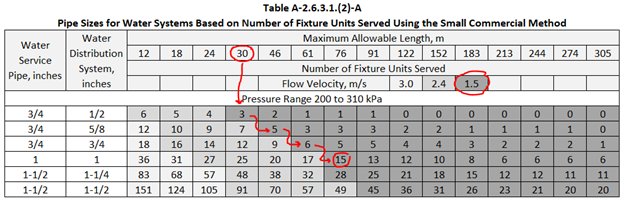
The example in the Notes to Part 2 of the BCPC goes through the sizing of each section of the water distribution system. When using Table A-2.6.3.1.(2)-A make sure to follow the steps described in the example. One technique that needs further explanation is how to determine a pipe size when a flow velocity shaded area does not continue in a maximum allowable length column. An example question can be used to clarify the use of the table.
Example question
When using Table A-2.6.3.1.(2)-A, what size is a copper hot water pipe serving 12 fixture units and using the maximum allowable length of 30m?
Solution
In the 30m column for maximum allowable length the only dark shaded number of fixture units allowed to be served for the velocity of 1.5 m/s is 3. To find the pipe size for 12 fixture units continue to slide right, and down, in the adjacent columns until a number equal to, or greater than, the 12 fixture unit load is found for 1.5 m/s flow velocity. For this example, the pipe size would be 1 inch, found under the 76m column as shown in the figure below.
Average pressure loss method
The BC Plumbing Code Figure A-2.6.3.1.(2)-A is an example of the water supply system for a commercial and residential development and is used with the average pressure loss pipe sizing method.
Table A-2.6.3.1.(2)-F, Pipe Sizes for Water Systems Based on Number of Fixture Units Served Using the Average Pressure Loss Method, is used for this method.
The average pressure loss method includes a Fixture Units Summary and is a good example of a worksheet that should be used to collect all the WSFU values for fixtures or devices. The example in the Code also has good examples of tables for sizing each section of the system, divided into the water service pipe, the hot water distribution system and the cold water distribution system.
Determining the minimum static pressure is very similar to the small commercial building method, except this method requires the plumber to calculate the pressure available for friction loss before using Table A-2.6.3.1.(2)-F.
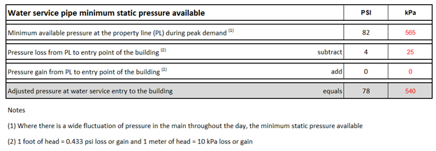
To use the table, the plumber can go through a similar process as used for the “Small commercial building” method. The static pressure available for the water service pipe can be determined using a worksheet like the one shown below.
| Water service pipe minimum static pressure available | PSI | kPa |
|---|---|---|
| Minimum available pressure at the property line (PL) during peak demand[6] | 82 | 565 |
| Pressure loss from PL to entry point of the building[7] | subtract 4 | subtract 25 |
| Pressure gain from PL to entry point of the building[8] | add 0 | add 0 |
| Adjusted pressure at water service entry to the building | equals 78 | equals 540 |
Once the adjusted pressure is known at the entry to the building the water distribution system pressure losses can be calculated. There is one additional pressure loss that must be considered when using this method: the governing fixture pressure requirement.
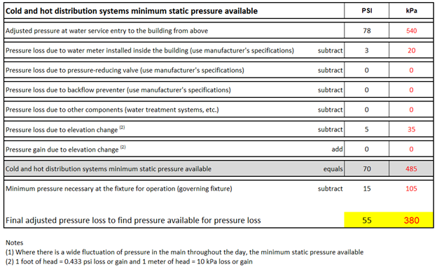
The worksheet below is similar to the one used for the small commercial building method, but with the cold and hot distribution systems minimum static pressure available reduced by the minimum pressure necessary at the fixture for operation (governing fixture).
| Cold and hot distribution systems minimum static pressure available | PSI | kPa |
|---|---|---|
| Adjusted pressure at water service entry to the building from above | 78 | 540 |
| Pressure loss due to water meter installed inside the building (use manufacturer's specifications) | subtract 3 | subtract 20 |
| Pressure loss due to pressure-reducing valve (use manufacturer's specifications) | subtract 0 | subtract 0 |
| Pressure loss due to backflow preventer (use manufacturer's specifications) | subtract 0 | subtract 0 |
| Pressure loss due to other components (water treatment systems, etc.) | subtract 0 | subtract 0 |
| Pressure loss due to elevation change[9] | subtract 5 | subtract 35 |
| Pressure gain due to elevation change[10] | add 0 | add 0 |
| Cold and hot distribution systems minimum static pressure available | equals 70 | equals 485 |
| Minimum pressure necessary at the fixture for operation (governing fixture) | subtract 15 | subtract 105 |
| Final adjusted pressure loss to find pressure available for pressure loss | 55 | 380 |
The minimum static pressure for the cold and hot water distribution systems can be calculated using a worksheet similar to the one used above, or using Figure A-2.6.3.1.(2)-B in the BCPC Notes to Part 2. Once the minimum static pressure and the developed length has been determined, the plumber uses the formula shown below, from Figure A-2.6.3.1.(2)-B Step 1(e), to calculate the pressure available for pressure loss.
Step 1(e)
[latex]\begin{array}{ccccc}380 \text{ kPa}&\div&114\text{m}&=&3.3\text{ kPa per metre}\\ \begin{array}{c}\text{Total pressure}\\ \text{available for}\\ \text{friction loss}\end{array}&&\begin{array}{c}\text{developed length} \times 1.5 \text{ for fittings}\\ \text{and/or additional losses if} \\ \text{insert fittings are used} \end{array}&& \begin{array}{c}\text{Average pressure loss}\\ \text{must be minimum} \\ \text{2.6 kPa per metre}\end{array}\end{array}[/latex]
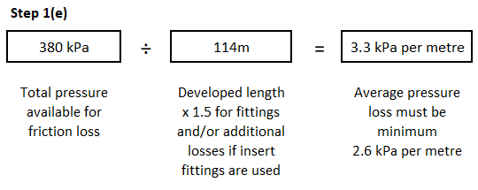
To use this method, and Table A-2.6.3.1.(2)-F, the pressure available for friction loss must be 2.6 kPa per metre (0.115 psi per foot) or more. If it is less than that, the system must be designed according to a detailed engineering design method. The pressure available for pressure loss is a simple way of making sure that, no matter what piping material is used, the friction loss will not create excessive pressure drop.
Industrial, Large Commercial, and Institutional Water Supply System Sizing
These systems are sized using a detailed engineering design as they generally require much higher volumes of water than residential and small commercial systems. Some of the water is used for domestic applications, such as water for human consumption, food preparation, or sanitation, but most of the water is for non-potable processes. Industrial, large commercial, and institutional applications can include pulp mills, hospitals, car washes, high-rise condominiums, hotels, swimming pools, etc.
Industrial, large commercial, and institutional systems can use a public or private source for their water supply. Many large applications will use public water for domestic use and any processes that require potable water, but may have a private supply, such as a site-constructed reservoir, for processes that could use non-potable water. The non-potable processes can include irrigation, chemical systems, specialized fixtures and equipment, etc. To prevent contamination of the public potable system, the BCPC Article 2.6.2.5 states that “No private water supply system shall be interconnected with a public water supply system.” If the application uses the public system for both the domestic uses and the non-potable processes, the piping arrangements will require an evaluation of possible cross-connections. The use of backflow preventers (cross connection devices) is very common on industrial, large commercial, and institutional water supply and distribution systems.
Now complete Self-Test 2 and check your answers.
Self-Test 2
Self-Test 2
- What is the minimum size (NPS) water service to a commercial building?
- ½ inch
- ¾ inch
- 1 inch
- 1¼ inch
- According to the NPC, what is the hydraulic load of a ¾ inch hose bibb for public use?
- 2.5 fixture units
- 3 fixture units
- 6 fixture units
- 7 fixture unit
- According to the Code, what is the hydraulic load of a bathtub with a ¾ inch spout for private use?
- 0.7 fixture units
- 1.4 fixture units
- 4 fixture units
- 10 fixture units
- According to the Code, what is the total hydraulic load on a branch that serves 5 direct flush valve urinals?
- 58 fixture units
- 53 fixture units
- 45 fixture units
- 35 fixture units
- What is the maximum water velocity permitted for cold water copper distribution systems, as recommended by copper tube manufacturers?
- 3.0 m/sec
- 2.4 m/sec
- 1.5 m/sec
- 1.2 m/sec
- When sizing a water supply system using the NPC, the final size of the water service pipe shall be what size?
- 75% of the combined fixture unit value
- The sum of the total hot and the total cold
- Sized for peak demand flow and not less than ¾″
- The sum of the cold water fixture unit values in the system plus 50%
- What water supply system sizing method would a plumber use to size the piping in a single family dwelling?
- Simplified method
- Simplified method or Average pressure loss method
- Simplified method, Average pressure loss method, or Small commercial building method
- Simplified method, Average pressure loss method, Small commercial building method, or a Detailed engineering design
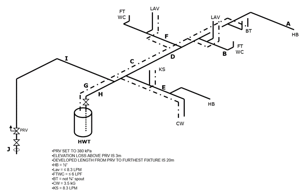
- Size the lettered building water supply system pipes on the drawing below.
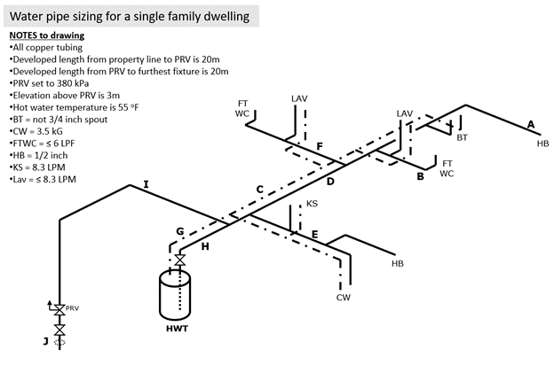
Competency B2 Learning Task 2 Quiz: Simplified method Copper tubing version Pipe or tube identifier Cold or hot piping WSFU load Notes Maximum water velocity based on material Pipe or tube size A B C D E F G H I J - Size the lettered building water supply system pipes on the drawing below.
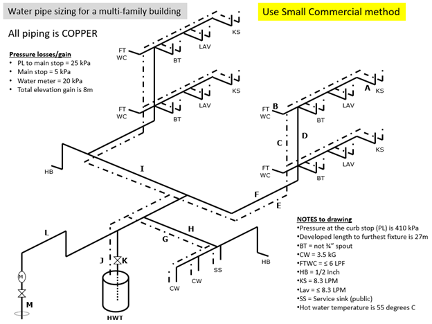
Competency B2 Learning Task 2 Quiz: Small commercial building method Copper tubing version Pipe or tube identifier Cold or hot piping WSFU load Notes Maximum water velocity based on material Pressure range Pipe or tube size A B C D E F G H I J K L M - Size the lettered building water supply system pipes on the drawing below.
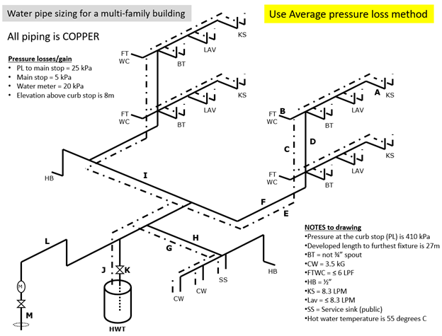
Competency B2 Learning Task 2 Quiz: Average pressure loss method Copper tubing version Pipe or tube identifier Cold or hot piping WSFU load Notes Maximum water velocity based on material Pipe or tube size
Check your answers using the Self-Test Answer Keys in Appendix 1.
Media Attributions
- Figure 1 An example of a simple piping layout using some common abbreviations by Scott Armor, Camosun College Piping Department is licensed under a CC BY 4.0 licence.
- Figure 2 TOTAL fixture load at the fixture spout by Scott Armor, Camosun College Piping Department is licensed under a CC BY 4.0 licence.
- Figure 3 Simple building water distribution system sketch by Camosun College is licensed under a CC BY 4.0 licence.
- Figure 4 Decreasing fixture unit values for direct flush valves John Gordon is licensed under a CC BY-NC-SA licence.
- Figure 5 An example of pressure loss due to elevation by Camosun College is licensed under a CC BY 4.0 licence.
- Figure 6 Service water heater possible connection locations to the distribution system by Scott Armor, Camosun College Piping Department is licensed under a CC BY 4.0 licence.
- Figure 7 Correct method to count WSFU load with the HWH connected in the middle by Scott Armor, Camosun College Piping Department is licensed under a CC BY 4.0 licence.
- Figure 8 How to use the table for the example question by Camosun College is licensed under a CC BY 4.0 licence.
- Where there is a wide fluctuation of pressure in the main throughout the day, the minimum static pressure available. ↵
- 1 foot of head = 0.443 psi loss or gain and 1 meter of head = 10 kPa loss or gain ↵
- 1 foot of head = 0.443 psi loss or gain and 1 meter of head = 10 kPa loss or gain ↵
- 1 foot of head = 0.443 psi loss or gain and 1 meter of head = 10 kPa loss or gain ↵
- 1 foot of head = 0.443 psi loss or gain and 1 meter of head = 10 kPa loss or gain ↵
